Nissan Pathfinder (2012 year). Instruction — part 604
DIRECT CLUTCH
TM-259
< UNIT DISASSEMBLY AND ASSEMBLY >
C
E
F
G
H
I
J
K
L
M
A
B
TM
N
O
P
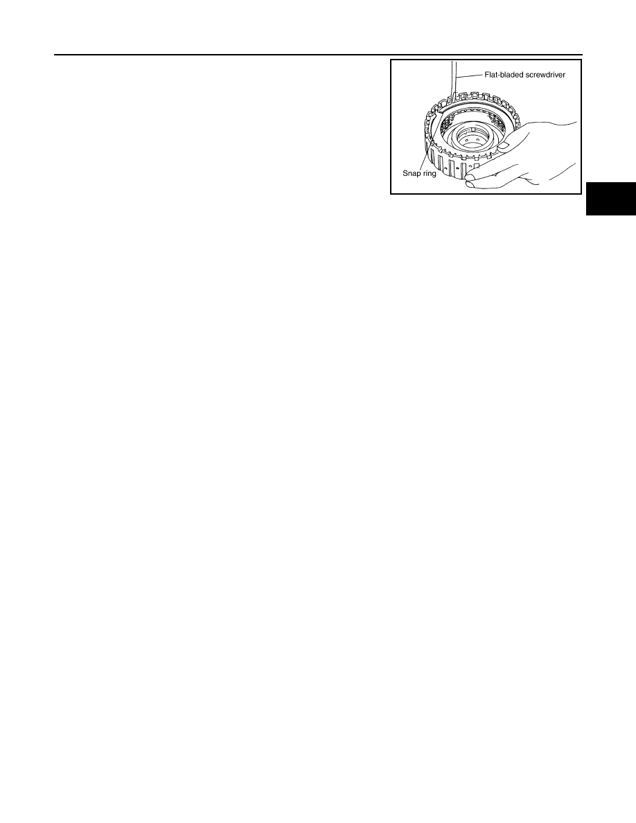
2. Install snap ring in direct clutch drum using suitable tool.
SCIA2868E
August 2012
2012 Pathfinder
TM-260
< UNIT DISASSEMBLY AND ASSEMBLY >
ASSEMBLY
ASSEMBLY
Assembly (1)
INFOID:0000000007357333
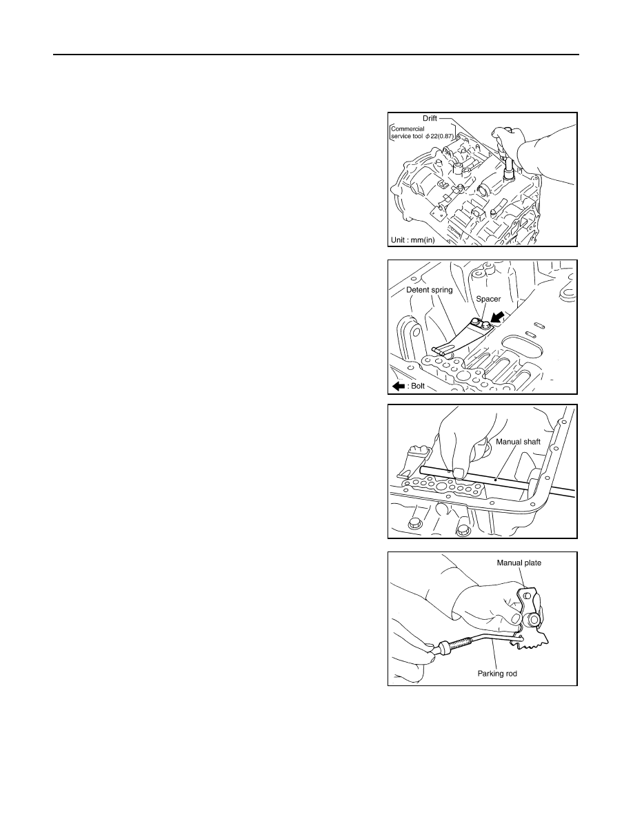
1. Drive instruction shaft oil seals into the transmission case until they
are flush using suitable tool.
CAUTION:
• Apply ATF to instruction shaft oil seals.
• Do not reuse instruction shaft oil seals.
2. Install detent spring and spacer in transmission case and secure
with the bolt.
3. Install instruction shaft to transmission case.
4. Install parking rod to instruction plate.
SCIA5259E
Bolt
: 7.9 N·m (0.81 kg-m, 70 in-lb)
SCIA5248E
SCIA5716E
SCIA5220E
August 2012
2012 Pathfinder
ASSEMBLY
TM-261
< UNIT DISASSEMBLY AND ASSEMBLY >
C
E
F
G
H
I
J
K
L
M
A
B
TM
N
O
P
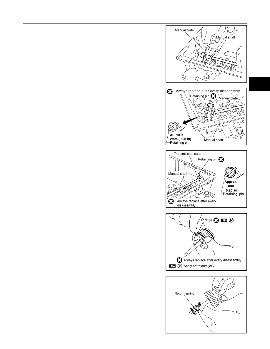
5. Install instruction plate (with parking rod) to instruction shaft.
6. Install retaining pin into the instruction plate and instruction shaft.
a. Align pinhole of the manual plate to pinhole of the manual shaft
using suitable tool.
b. Tap the retaining pin into the instruction plate using suitable tool.
CAUTION:
• Drive retaining pin to 2
±
0.5 mm (0.08
±
0.020 in) over the
instruction plate.
• Do not reuse retaining pin.
7. Install retaining pin into the transmission case and instruction shaft.
a. Align pinhole of the transmission case to pinhole of the instruction
shaft using suitable tool.
b. Tap the retaining pin into the transmission case using suitable
tool.
CAUTION:
• Drive retaining pin to 5
±
1 mm (0.20
±
0.04 in) over the
transmission case.
• Do not reuse retaining pin.
8. Install O-rings to servo assembly.
CAUTION:
• Do not reuse O-rings.
• Apply petroleum jelly to O-rings.
9. Install return spring to servo assembly.
SCIA5715E
SCIA5297E
SCIA2427E
SCIA5719E
SCIA5717E
August 2012
2012 Pathfinder
TM-262
< UNIT DISASSEMBLY AND ASSEMBLY >
ASSEMBLY
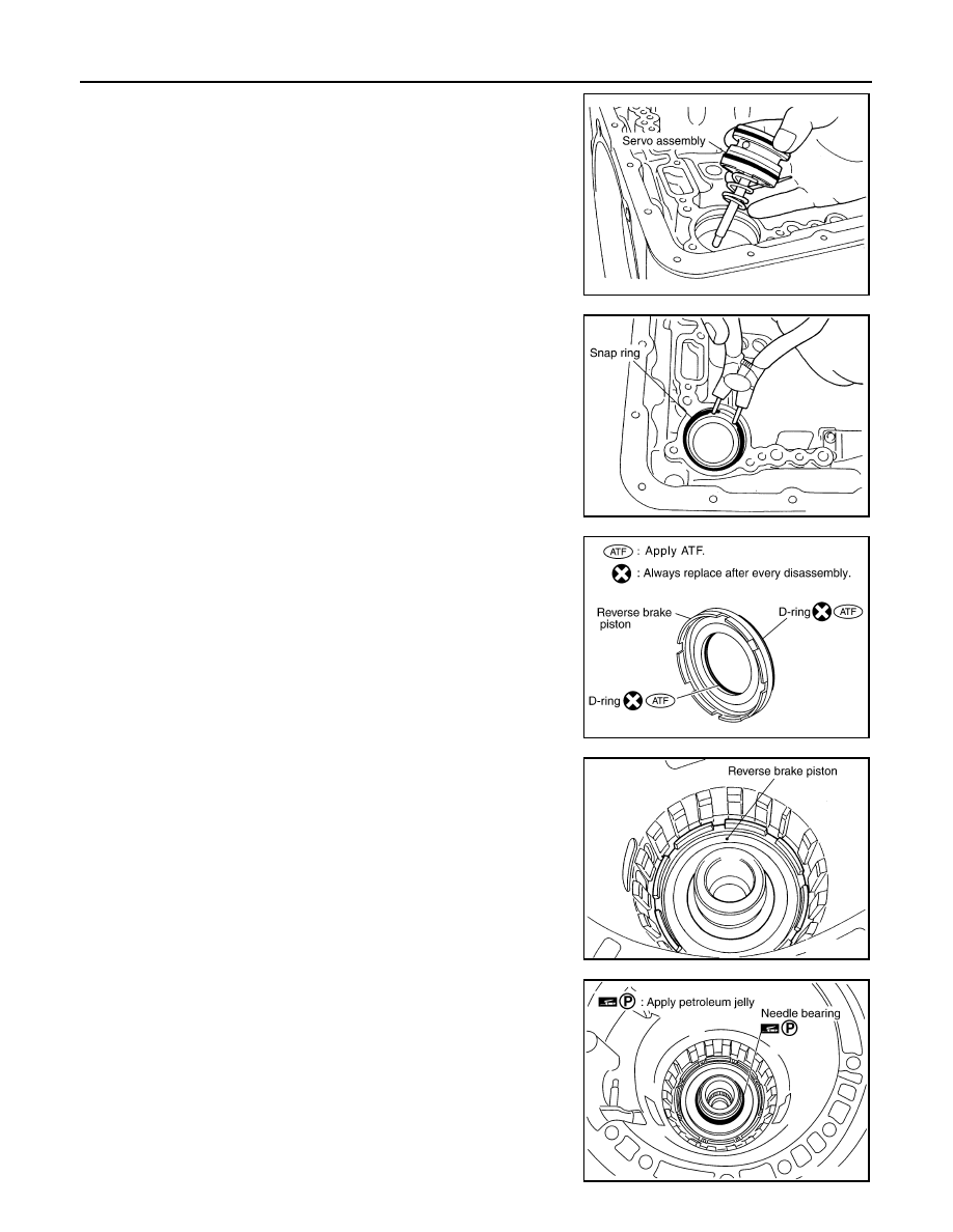
10. Install servo assembly in transmission case.
11. Install snap ring to transmission case using suitable tool.
12. Install D-rings in reverse brake piston.
CAUTION:
• Do not reuse D-rings.
• Apply ATF to D-rings.
13. Install reverse brake piston in transmission case.
14. Install needle bearing to drum support edge surface.
CAUTION:
Apply petroleum jelly to needle bearing.
SCIA5679E
SCIA2333E
SCIA6330E
SCIA2325E
SCIA2796E
August 2012
2012 Pathfinder
ASSEMBLY
TM-263
< UNIT DISASSEMBLY AND ASSEMBLY >
C
E
F
G
H
I
J
K
L
M
A
B
TM
N
O
P
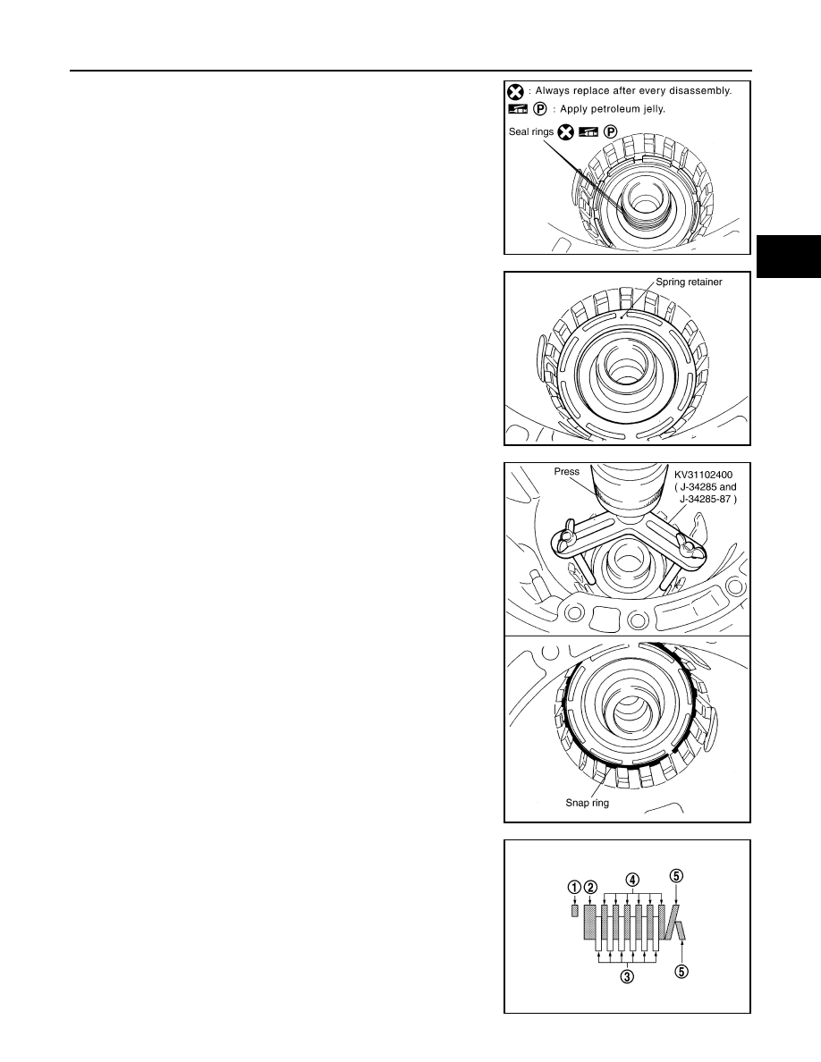
15. Install seal rings to drum support.
CAUTION:
• Do not reuse seal rings.
• Apply petroleum jelly to seal rings.
16. Install spring retainer and return spring in transmission case.
17. Install snap ring in transmission case while compressing return
spring using Tool.
CAUTION:
Securely assemble them using a flat-bladed screwdriver so
that snap ring tension is slightly weak.
18. Install reverse brake drive plates, driven plates and dish plates
in transmission case.
CAUTION:
Take care with order of plates.
• VQ40DE models
- Snap ring (1)
- Retaining plate (2)
- Drive plate (3)
- Driven plate (4)
- Dish plate (5)
- Drive plate/Driven plate:6/6
SCIA3333E
SCIA2324E
Tool number
: KV31102400 (J-34285 and J-34285-87)
SCIA5877E
SCIA6949E
August 2012
2012 Pathfinder
TM-264
< UNIT DISASSEMBLY AND ASSEMBLY >
ASSEMBLY
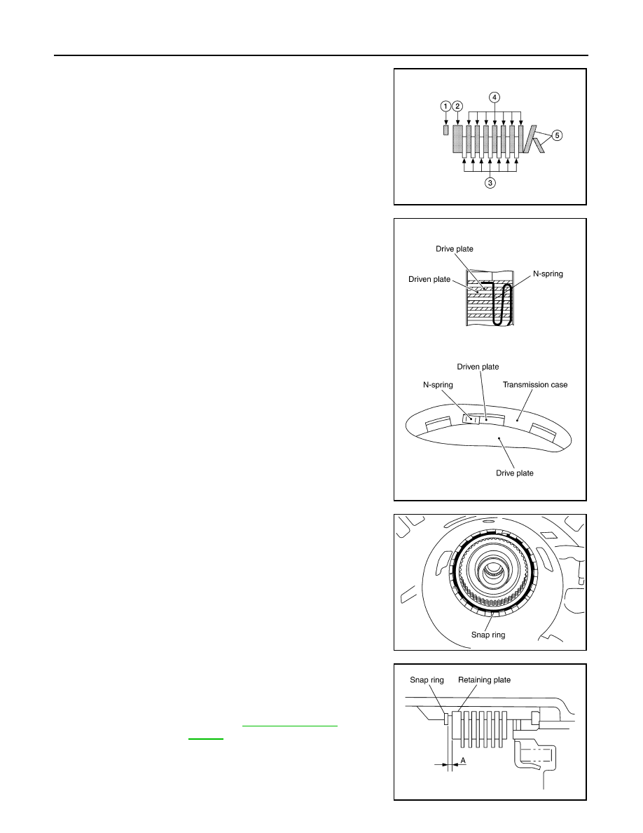
• VK56DE models
- Snap ring (1)
- Retaining plate (2)
- Drive plate (3)
- Driven plate (4)
- Dish plate (5)
- Drive plate/Driven plate: 7/7
19. Assemble N-spring.
20. Install reverse brake retaining plate in transmission case.
21. Install snap ring in transmission case.
22. Measure clearance (A) between retaining plate and snap ring. If
not within specified clearance, select proper retaining plate.
WCIA0625E
SCIA5249E
SCIA2439E
Clearance “A”
: 0.7 - 1.1mm (0.028 - 0.043 in)
Retaining plate
: Refer to
SCIA3129E
August 2012
2012 Pathfinder
ASSEMBLY
TM-265
< UNIT DISASSEMBLY AND ASSEMBLY >
C
E
F
G
H
I
J
K
L
M
A
B
TM
N
O
P
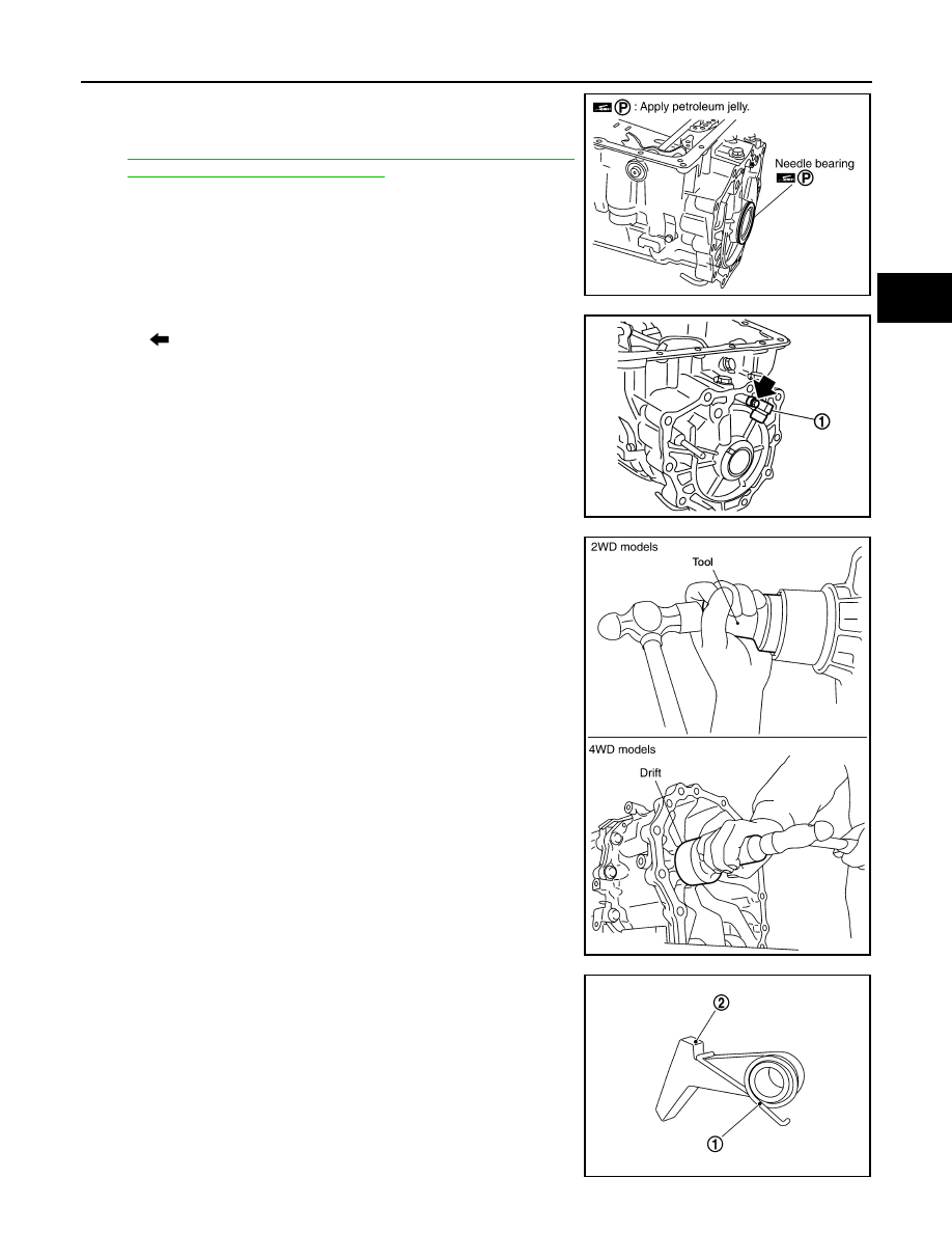
23. Install needle bearing to transmission case.
CAUTION:
• Take care with the direction of needle bearing. Refer to
TM-217, "Location of Adjusting Shims, Needle Bearings,
Thrust Washers and Snap Rings"
.
• Apply petroleum jelly to needle bearing.
24. Install output speed sensor (1) to transmission case and tighten
bolt (
) to specified torque.
CAUTION:
• Do not subject sensor to impact by dropping or hitting it.
• Do not disassemble sensor.
• Do not allow metal filings or any foreign material to get on
the sensor's front edge magnetic area.
• Do not place sensor in an area affected by magnetism.
25. Install new rear oil seal until it is flush into the rear extension
case (2WD models) using Tool or adapter case (4WD models)
using suitable tool.
CAUTION:
• Apply ATF to rear oil seal.
• Do not reuse rear oil seal.
26. Install return spring (1) to parking pawl (2).
SCIA5031E
Output speed sensor bolt : 5.8 N·m (0.59 kg-m, 51 in-lb)
JSDIA1321ZZ
Tool number
: ST33400001 (J-26082)
WCIA0475E
SCIA6180J
August 2012
2012 Pathfinder
TM-266
< UNIT DISASSEMBLY AND ASSEMBLY >
ASSEMBLY
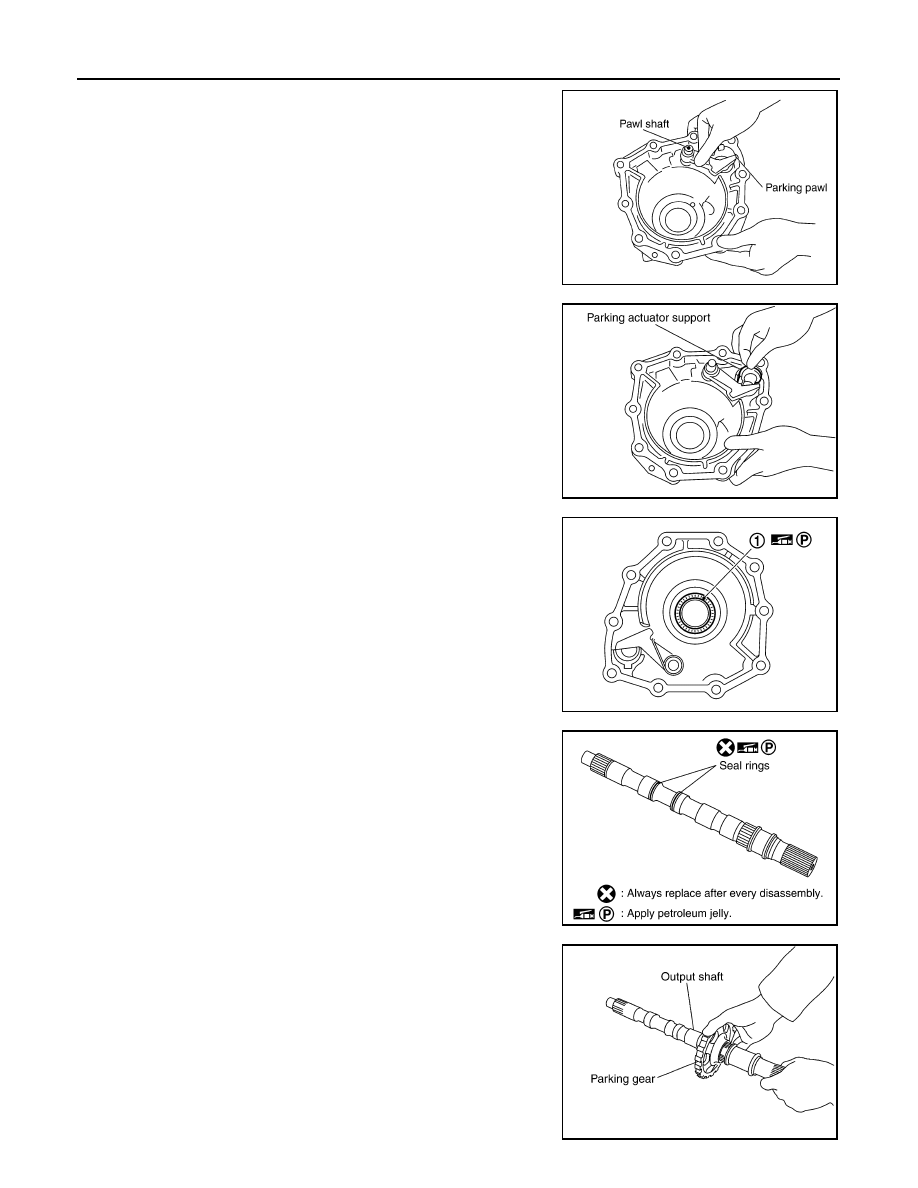
27. Install parking pawl (with return spring) and pawl shaft to rear
extension (2WD models) or adapter case (4WD models).
28. Install parking actuator support to rear extension (2WD models)
or adapter case (4WD models).
29. Install needle bearing (1) to rear extension (2WD models) or
adapter case (4WD models).
CAUTION:
Apply petroleum jelly to needle bearing.
30. Install seal rings to output shaft.
CAUTION:
• Do not reuse seal rings.
• Apply petroleum jelly to seal rings.
31. Install parking gear to output shaft.
SCIA3424E
SCIA3423E
SCIA6179J
SCIA5209E
SCIA5247E
August 2012
2012 Pathfinder
Нет комментариевНе стесняйтесь поделиться с нами вашим ценным мнением.
Текст