Nissan Pathfinder (2012 year). Instruction — part 98
BRC-50
< DTC/CIRCUIT DIAGNOSIS >
[TYPE 1]
C1116 STOP LAMP SWITCH
C1116 STOP LAMP SWITCH
Description
INFOID:0000000007356719
The stop lamp switch transmits the stop lamp switch signal (ON/OFF) to the ABS actuator and electric unit
(control unit).
DTC Logic
INFOID:0000000007356720
DTC DETECTION LOGIC
DTC CONFIRMATION PROCEDURE
1.
CHECK SELF-DIAGNOSIS RESULTS
Check the self-diagnosis results.
Is above displayed on the self-diagnosis display?
YES
>> Proceed to diagnosis procedure. Refer to
.
NO
>> Inspection End.
Diagnosis Procedure
INFOID:0000000007356721
Regarding Wiring Diagram information, refer to
BRC-88, "Wiring Diagram - With VQ40DE"
1.
CONNECTOR INSPECTION
1. Disconnect ABS actuator and electric unit (control unit) connector and stop lamp switch connector.
2. Check the terminals for deformation, disconnection, looseness or damage.
Is the inspection result normal?
YES
>> GO TO 2
NO
>> Repair or replace as necessary.
2.
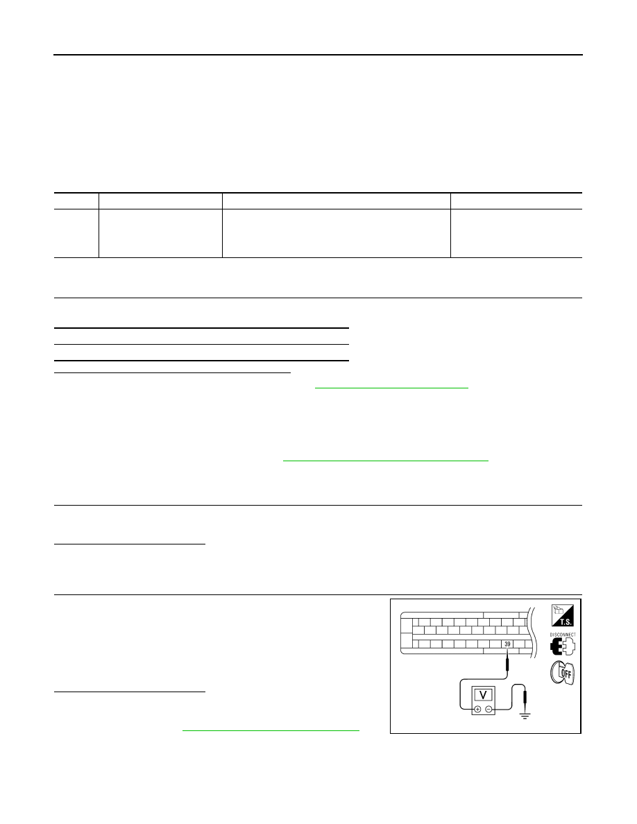
STOP LAMP SWITCH INSPECTION
Check voltage between ABS actuator and electric unit (control unit)
connector E125 terminal 39 and body ground.
Is the inspection result normal?
YES
>> Perform self-diagnosis again. If the same results
appear, replace ABS actuator and electric unit (control
unit). Refer to
BRC-112, "Removal and Installation"
NO
>> Repair or replace malfunctioning components.
DTC
Display item
Malfunction detected condition
Possible cause
C1116
STOP LAMP SW
When stop lamp switch circuit is open.
• Harness or connector
• Stop lamp switch
• ABS actuator and electric unit
(control unit)
Self-diagnosis results
STOP LAMP SW
Brake pedal depressed
: Battery voltage
(approx. 12V)
Brake pedal released
: Approx. 0V
AWFIA0472ZZ
August 2012
2012 Pathfinder

C1116 STOP LAMP SWITCH
BRC-51
< DTC/CIRCUIT DIAGNOSIS >
[TYPE 1]
C
D
E
G
H
I
J
K
L
M
A
B
BRC
N
O
P
Special Repair Requirement
INFOID:0000000007818444
1.
ADJUSTMENT OF STEERING ANGLE SENSOR NEUTRAL POSITION
Always perform neutral position adjustment for the steering angle sensor when replacing the ABS actuator
and electric unit (control unit). Refer to
BRC-12, "ADJUSTMENT OF STEERING ANGLE SENSOR NEUTRAL
.
>> GO TO 2
2.
CALIBRATION OF DECEL G SENSOR
Always perform calibration of decel G sensor when replacing the ABS actuator and electric unit (control unit).
BRC-13, "CALIBRATION OF DECEL G SENSOR : Description"
.
>> END
August 2012
2012 Pathfinder

BRC-52
< DTC/CIRCUIT DIAGNOSIS >
[TYPE 1]
C1120, C1122, C1124, C1126 IN ABS SOL
C1120, C1122, C1124, C1126 IN ABS SOL
Description
INFOID:0000000007356723
The solenoid valve increases, holds or decreases the fluid pressure of each brake caliper according to the sig-
nals transmitted by the ABS actuator and electric unit (control unit).
DTC Logic
INFOID:0000000007356724
DTC DETECTION LOGIC
DTC CONFIRMATION PROCEDURE
1.
CHECK SELF-DIAGNOSIS RESULTS
Check the self-diagnosis results.
Is above displayed on the self-diagnosis display?
YES
>> Proceed to diagnosis procedure. Refer to
.
NO
>> Inspection End.
Diagnosis Procedure
INFOID:0000000007356725
Regarding Wiring Diagram information, refer to
BRC-88, "Wiring Diagram - With VQ40DE"
1.
CONNECTOR INSPECTION
1. Turn ignition switch OFF.
2. Disconnect ABS actuator and electric unit (control unit) connector.
3. Check terminal for deformation, disconnection, looseness, and so on. If any malfunction is found, repair or
replace terminal.
4. Reconnect connectors and then perform the self-diagnosis. Refer to
.
Is any item indicated on the self-diagnosis display?
YES
>> GO TO 2
NO
>> Poor connection of connector terminal. Repair or replace connector.
2.
CHECK SOLENOID, VDC SWITCH-OVER VALVE AND ACTUATOR RELAY POWER SUPPLY CIRCUIT
DTC
Display item
Malfunction detected condition
Possible cause
C1120
FR LH IN ABS SOL
When the control unit detects a malfunction in the front
LH inlet solenoid circuit.
• ABS actuator and electric unit
(control unit)
C1122
FR RH IN ABS SOL
When the control unit detects a malfunction in the front
RH inlet solenoid circuit.
C1124
RR LH IN ABS SOL
When the control unit detects a malfunction in the rear LH
inlet solenoid circuit.
C1126
RR RH IN ABS SOL
When the control unit detects a malfunction in the rear
RH inlet solenoid circuit.
Self-diagnosis results
FR LH IN ABS SOL
FR RH IN ABS SOL
RR LH IN ABS SOL
RR RH IN ABS SOL
August 2012
2012 Pathfinder
C1120, C1122, C1124, C1126 IN ABS SOL
BRC-53
< DTC/CIRCUIT DIAGNOSIS >
[TYPE 1]
C
D
E
G
H
I
J
K
L
M
A
B
BRC
N
O
P
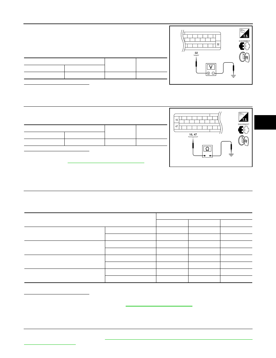
1. Turn ignition switch OFF.
2. Disconnect ABS actuator and electric unit (control unit) connec-
tor.
3. Check voltage between ABS actuator and electric unit (control
unit) connector E125 terminal 32 and ground.
Is the inspection result normal?
YES
>> GO TO 3
NO
>> Repair or replace malfunctioning components.
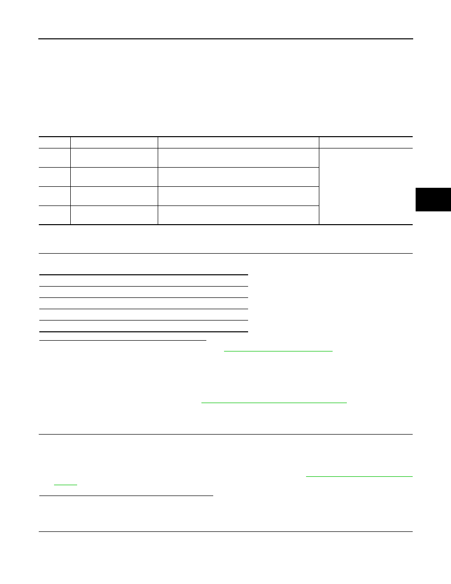
3.
CHECK SOLENOID, VDC SWITCH-OVER VALVE AND ACTUATOR RELAY GROUND CIRCUIT
Check continuity between ABS actuator and electric unit (control
unit) connector E125 terminals 16, 47 and ground.
Is the inspection result normal?
YES
>> Replace ABS actuator and electric unit (control unit).
BRC-112, "Removal and Installation"
.
NO
>> Repair or replace malfunctioning components.
Component Inspection
INFOID:0000000007356726
1.
CHECK ACTIVE TEST
1. Select each test menu item on ”ACTIVE TEST“.
2. On the display, touch “Up”, “Keep”, and “Down”, and check that the system operates as shown in the table
below.
*: On for 1 to 2 seconds after the touch, and then Off
Is the inspection result normal?
YES
>> Inspection End.
NO
>> Go to diagnosis procedure. Refer to
Special Repair Requirement
INFOID:0000000007818450
1.
ADJUSTMENT OF STEERING ANGLE SENSOR NEUTRAL POSITION
Always perform neutral position adjustment for the steering angle sensor when replacing the ABS actuator
and electric unit (control unit). Refer to
BRC-12, "ADJUSTMENT OF STEERING ANGLE SENSOR NEUTRAL
.
ABS actuator and electric unit (control unit)
—
Voltage
Connector
Terminal
E125
32
Ground
Battery voltage
AWFIA0018ZZ
ABS actuator and electric unit (control unit)
—
Continuity
Connector
Terminal
E125
16, 47
Ground
Yes
AWFIA0016ZZ
Operation
ABS solenoid valve
Up
Keep
Down
FR RH SOL
FR RH IN SOL
Off
On
On
FR RH OUT SOL
Off
Off
On*
FR LH SOL
FR LH IN SOL
Off
On
On
FR LH OUT SOL
Off
Off
On*
RR RH SOL
RR RH IN SOL
Off
On
On
RR RH OUT SOL
Off
Off
On*
RR LH SOL
RR LH IN SOL
Off
On
On
RR LH OUT SOL
Off
Off
On*
August 2012
2012 Pathfinder
BRC-54
< DTC/CIRCUIT DIAGNOSIS >
[TYPE 1]
C1120, C1122, C1124, C1126 IN ABS SOL
>> GO TO 2
2.
CALIBRATION OF DECEL G SENSOR
Always perform calibration of decel G sensor when replacing the ABS actuator and electric unit (control unit).
BRC-13, "CALIBRATION OF DECEL G SENSOR : Description"
.
>> END
August 2012
2012 Pathfinder
C1121, C1123, C1125, C1127 OUT ABS SOL
BRC-55
< DTC/CIRCUIT DIAGNOSIS >
[TYPE 1]
C
D
E
G
H
I
J
K
L
M
A
B
BRC
N
O
P
C1121, C1123, C1125, C1127 OUT ABS SOL
Description
INFOID:0000000007356728
The solenoid valve increases, holds or decreases the fluid pressure of each brake caliper according to the sig-
nals transmitted by the ABS actuator and electric unit (control unit).
DTC Logic
INFOID:0000000007356729
DTC DETECTION LOGIC
DTC CONFIRMATION PROCEDURE
1.
CHECK SELF-DIAGNOSIS RESULTS
Check the self-diagnosis results.
Is above displayed on the self-diagnosis display?
YES
>> Proceed to diagnosis procedure. Refer to
.
NO
>> Inspection End.
Diagnosis Procedure
INFOID:0000000007818472
Regarding Wiring Diagram information, refer to
BRC-88, "Wiring Diagram - With VQ40DE"
1.
CONNECTOR INSPECTION
1. Turn ignition switch OFF.
2. Disconnect ABS actuator and electric unit (control unit) connector.
3. Check terminal for deformation, disconnection, looseness, and so on. If any malfunction is found, repair or
replace terminal.
4. Reconnect connectors and then perform the self-diagnosis. Refer to
.
Is any item indicated on the self-diagnosis display?
YES
>> GO TO 2
NO
>> Poor connection of connector terminal. Repair or replace connector.
2.
CHECK SOLENOID, VDC SWITCH-OVER VALVE AND ACTUATOR RELAY POWER SUPPLY CIRCUIT
DTC
Display item
Malfunction detected condition
Possible cause
C1121
FR LH OUT ABS SOL
When the control unit detects a malfunction in the front
LH outlet solenoid circuit.
• ABS actuator and electric unit
(control unit)
C1123
FR RH OUT ABS SOL
When the control unit detects a malfunction in the front
RH outlet solenoid circuit.
C1125
RR LH OUT ABS SOL
When the control unit detects a malfunction in the rear LH
outlet solenoid circuit.
C1127
RR RH OUT ABS SOL
When the control unit detects a malfunction in the rear
RH outlet solenoid circuit.
Self-diagnosis results
FR LH OUT ABS SOL
FR RH OUT ABS SOL
RR LH OUT ABS SOL
RR RH OUT ABS SOL
August 2012
2012 Pathfinder
BRC-56
< DTC/CIRCUIT DIAGNOSIS >
[TYPE 1]
C1121, C1123, C1125, C1127 OUT ABS SOL
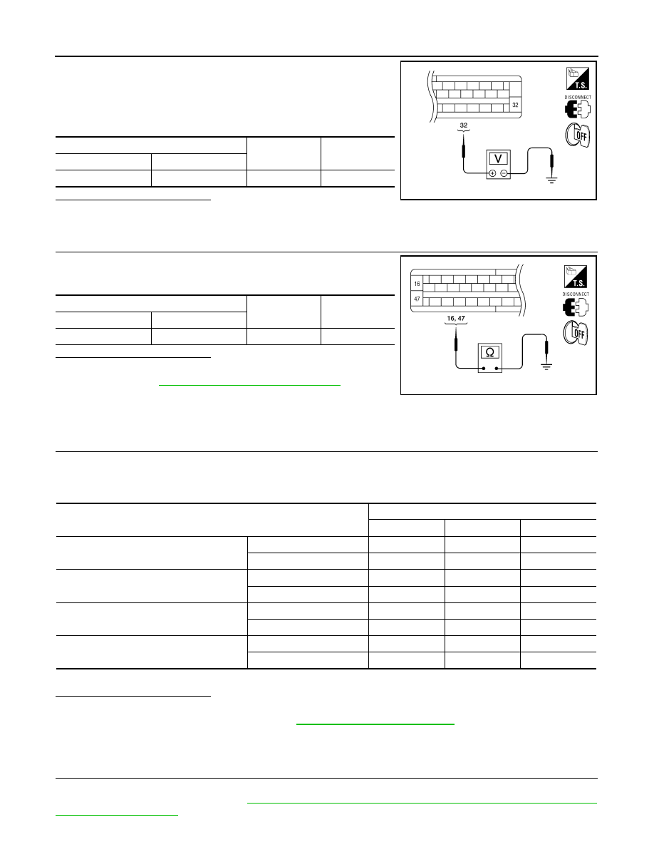
1. Turn ignition switch OFF.
2. Disconnect ABS actuator and electric unit (control unit) connec-
tor.
3. Check voltage between ABS actuator and electric unit (control
unit) connector E125 terminal 32 and ground.
Is the inspection result normal?
YES
>> GO TO 3
NO
>> Repair or replace malfunctioning components.
3.
CHECK SOLENOID, VDC SWITCH-OVER VALVE AND ACTUATOR RELAY GROUND CIRCUIT
Check continuity between ABS actuator and electric unit (control
unit) connector E125 terminals 16, 47 and ground.
Is the inspection result normal?
YES
>> Replace ABS actuator and electric unit (control unit).
BRC-112, "Removal and Installation"
.
NO
>> Repair or replace malfunctioning components.
Component Inspection
INFOID:0000000007818473
1.
CHECK ACTIVE TEST
1. Select each test menu item on ”ACTIVE TEST“.
2. On the display, touch “Up”, “Keep”, and “Down”, and check that the system operates as shown in the table
below.
*: On for 1 to 2 seconds after the touch, and then Off
Is the inspection result normal?
YES
>> Inspection End.
NO
>> Go to diagnosis procedure. Refer to
Special Repair Requirement
INFOID:0000000007818451
1.
ADJUSTMENT OF STEERING ANGLE SENSOR NEUTRAL POSITION
Always perform neutral position adjustment for the steering angle sensor when replacing the ABS actuator
and electric unit (control unit). Refer to
BRC-12, "ADJUSTMENT OF STEERING ANGLE SENSOR NEUTRAL
.
ABS actuator and electric unit (control unit)
—
Voltage
Connector
Terminal
E125
32
Ground
Battery voltage
AWFIA0018ZZ
ABS actuator and electric unit (control unit)
—
Continuity
Connector
Terminal
E125
16, 47
Ground
Yes
AWFIA0016ZZ
Operation
ABS solenoid valve
Up
Keep
Down
FR RH SOL
FR RH IN SOL
Off
On
On
FR RH OUT SOL
Off
Off
On*
FR LH SOL
FR LH IN SOL
Off
On
On
FR LH OUT SOL
Off
Off
On*
RR RH SOL
RR RH IN SOL
Off
On
On
RR RH OUT SOL
Off
Off
On*
RR LH SOL
RR LH IN SOL
Off
On
On
RR LH OUT SOL
Off
Off
On*
August 2012
2012 Pathfinder
C1121, C1123, C1125, C1127 OUT ABS SOL
BRC-57
< DTC/CIRCUIT DIAGNOSIS >
[TYPE 1]
C
D
E
G
H
I
J
K
L
M
A
B
BRC
N
O
P
>> GO TO 2
2.
CALIBRATION OF DECEL G SENSOR
Always perform calibration of decel G sensor when replacing the ABS actuator and electric unit (control unit).
BRC-13, "CALIBRATION OF DECEL G SENSOR : Description"
.
>> END
August 2012
2012 Pathfinder
Нет комментариевНе стесняйтесь поделиться с нами вашим ценным мнением.
Текст