Nissan Pathfinder (2012 year). Instruction — part 393
2012
QUICK REFERENCE CHART: PATHFINDER
Brake Specifications
INFOID:0000000007837578
Unit: mm (in)
Brake Pedal
INFOID:0000000007837579
ADJUSTABLE PEDAL
Unit: mm (in)
CAUTION:
When equipped with adjustable pedal, the pedal must be in the forward most position (closest to the floor) for pedal height
adjustment.
STANDARD PEDAL
Application
VQ40DE
VK56DE
Front brake
Brake model
CLZ33VB
Rotor outer diameter
×
thickness
296
×
28 (11.654
×
1.102)
320 x 28 (12.598 x 1.102)
Pad Length
×
width
×
thickness
140
×
50.5
×
10.0 (5.512
×
1.988
×
0.394)
130
×
52.3
×
11.0 (5.118
×
2.059
×
0.433)
Cylinder bore diameter (each)
46.4 (1.827)
45.0 (1.772)
Rear brake
Brake model
CLZ14VB
Rotor outer diameter
×
thickness
308
×
18 (12.126
×
0.709)
Pad Length
×
width
×
thickness
87.6
×
37.0
×
11.0 (3.449
×
1.457
×
0.433)
Cylinder bore diameter
38.1 (1.500)
Control valve
Valve model
Electric brake force distribution
Brake booster
Booster model
C215T
Diaphragm diameter
215 (8.465)
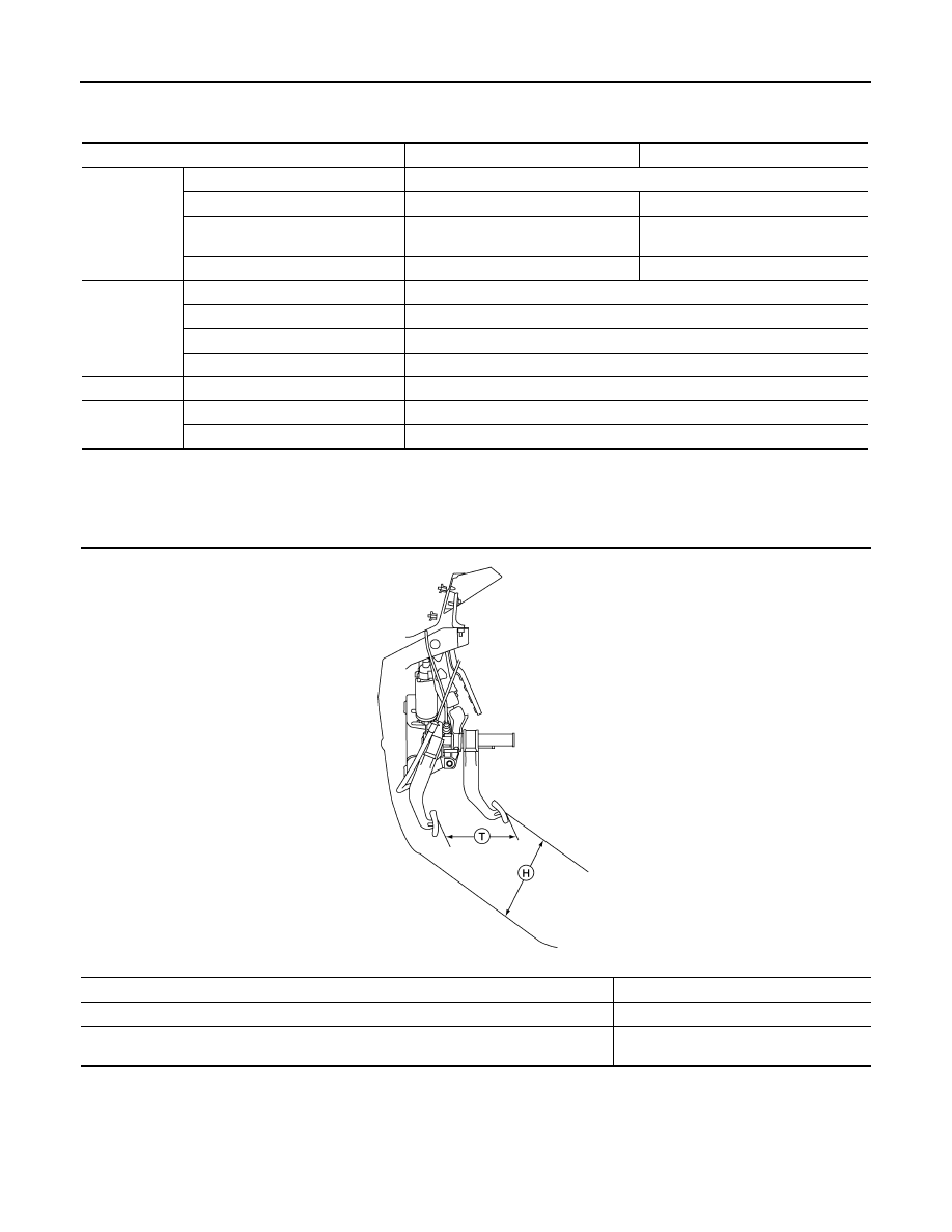
Pedal free height (H) with pedal in forward most position
182.1 (7.17)
Pedal full stroke (T)
153 (6.02)
Clearance between brake pedal bracket and threaded end of stop lamp switch and ASCD
cancel switch
0.74 - 1.96 (0.029 - 0.077)
ALFIA0149ZZ
QUICK REFERENCE CHART: PATHFINDER
2012
Unit: mm (in)
Front Disc Brake
INFOID:0000000007837576
Unit: mm (in)
Rear Disc Brake
INFOID:0000000007837577
Unit: mm (in)
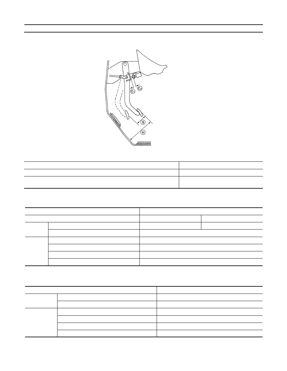
Pedal free height (H)
182.1 (7.17)
Pedal full stroke (S)
153 (6.02)
Clearance between brake pedal bracket (C
1
) and threaded end of stop lamp switch and
ASCD cancel switch (C
2
)
0.74 - 1.96 (0.029 - 0.077)
AWFIA0433ZZ
Brake model
CLZ33VB
Application
VQ40DE
VQ56DE
Brake pad
Standard thickness (new)
10.0 (0.394)
11.0 (0.043)
Minimum thickness
2.0 (0.079)
Disc rotor
Standard thickness (new)
28.0 (1.102)
Minimum thickness
26.0 (1.024)
Maximum uneven wear (measured at 8 positions)
0.015 (0.0006)
Runout limit (with it attached to the vehicle)
0.05 (0.0020)
Brake model
CLZ14VB
Brake pad
Standard thickness (new)
11.0 (0.433)
Minimum thickness
2.0 (0.079)
Disc rotor
Standard thickness (new)
18.0 (0.709)
Minimum thickness
16.0 (0.630)
Maximum uneven wear (measured at 8 positions)
0.015 (0.0006)
Runout limit (with it attached to the vehicle)
0.05 (0.0020)
2012
QUICK REFERENCE CHART: PATHFINDER
FOR USA AND CANADA : Fluids and Lubricants
INFOID:0000000007837569
FOR MEXICO
FOR MEXICO : Fluids and Lubricants
INFOID:0000000007837572
Description
Capacity (Approximate)
Metric
US measure
Imp measure
Fuel
80
21 1/8 gal
17 5/8 gal
Engine oil
Drain and refill
With oil filter
change
VQ40DE
5.1
5 3/8 qt
4 1/2 qt
VK56DE
6.5
6 7/8 qt
5 3/4 qt
Without oil filter
change
VQ40DE
4.8
5 1/8 qt
4 1/4 qt
VK56DE
6.2
6 1/2 qt
5 1/2 qt
Dry engine (engine overhaul)
VQ40DE
6.3
6 5/8 qt
5 1/2 qt
VK56DE
7.6
8 qt
6 3/4 qt
Cooling system
(with reservoir at “MAX” lev-
el)
Without rear A/C
VQ40DE
10.2
10 3/4 qt
9 qt
With rear
A/C
VQ40DE
VK56DE
13.4
14 1/8 qt
11 3/4 qt
Automatic transmission fluid (ATF)
VQ40DE
10.3
10 7/8 qt
9 1/8 qt
VK56DE
10.6
11 1/4 qt
9 3/8 qt
Rear final drive oil
VQ40DE
1.4
3 pt
2 1/2 pt
VK56DE
1.75
3 3/4 pt
3 1/8 pt
Transfer fluid
ATX14B
3.0
3 1/8 qt
2 5/8 qt
TX15B
2.0
2 1/8 qt
1 3/4 qt
Front final drive oil
VQ40DE
0.85
1 3/4 pt
1 1/2 pt
VK56DE
1.6
3 3/8 pt
2 7/8 pt
Power steering fluid (PSF)
1.0
2 1/8 pt
1 3/4 pt
Brake fluid
—
—
—
Multi-purpose grease
—
—
—
Windshield washer fluid
4.5
1 1/4 gal
1 gal
A/C system
refrigerant
Without rear A/C
0.70
±
0.05 kg
1.54
±
0.11 lb
1.54
±
0.11 lb
With rear A/C
0.85
±
0.05 kg
1.87
±
0.11 lb
1.87
±
0.11 lb
A/C system oil
Without rear A/C
180 m
6.1 fl oz
6.3 fl oz
With Rear A/C
210 m
7.1 fl oz
7.4 fl oz
Description
Capacity (Approximate)
Metric
US measure
Imp measure
Fuel
80
21 1/8 gal
17 5/8 gal
Engine oil
Drain and refill
With oil filter change
5.1
5 3/8 qt
4 1/2 qt
Without oil filter change
4.8
5 1/8 qt
4 1/4 qt
Dry engine (engine overhaul)
6.3
6 5/8 qt
5 1/2 qt
Cooling system
(with reservoir at “MAX” level)
13.4
14 1/8 qt
11 3/4 qt
QUICK REFERENCE CHART: PATHFINDER
2012
Automatic transmission fluid (ATF)
10.3
10 7/8 qt
9 1/8 qt
Rear final drive oil
1.4
3 pt
2 1/2 pt
Transfer fluid
ATX14B
3.0
3 1/8 qt
2 5/8 qt
Front final drive oil
0.85
1 3/4 pt
1 1/2 pt
Power steering fluid (PSF)
1.0
2 1/8 pt
1 3/4 pt
Brake fluid
—
—
—
Multi-purpose grease
—
—
—
Windshield washer fluid
4.5
1 1/4 gal
1 gal
A/C system refrigerant
0.85
±
0.05 kg
1.87
±
0.11 lb
1.87
±
0.11 lb
A/C system oil
210 m
7.1 fl oz
7.4 fl oz
Description
Capacity (Approximate)
Metric
US measure
Imp measure
GI-1
GENERAL INFORMATION
C
D
E
F
G
H
I
J
K
L
M
B
GI
SECTION
GI
N
O
P
CONTENTS
GENERAL INFORMATION
HOW TO USE THIS MANUAL . . . . . ..
HOW TO USE THIS MANUAL . . . . . . .
Description . . . . . . . . . . . . . . . ....
Terms . . . . . . . . . . . . . . . . . ....
Units . . . . . . . . . . . . . . . . . . ..
Contents . . . . . . . . . . . . . . . . ....
Relation between Illustrations and Descriptions . ...
Components . . . . . . . . . . . . . . . ..
HOW TO FOLLOW TROUBLE DIAGNOSES . .
Description . . . . . . . . . . . . . . . ....
How to Follow Test Groups in Trouble Diagnosis . ..
Key to Symbols Signifying Measurements or Pro-
cedures . . . . . . . . . . . . . . . . .....
HOW TO READ WIRING DIAGRAMS . . . .
Connector symbols . . . . . . . . . . . . ...
Sample/wiring diagram -example- . . . . . . ...
Description . . . . . . . . . . . . . . . ..
ABBREVIATIONS . . . . . . . . . . . ..
Abbreviation List . . . . . . . . . . . . . ..
RECOMMENDED CHEMICAL PRODUCTS
AND SEALANTS . . . . . . . . . . . .
Recommended Chemical Products and Sealants .
TERMINOLOGY . . . . . . . . . . . . .
ISO 15031-2 Terminology List . . . . . . . .
TIGHTENING TORQUE OF STANDARD
BOLTS . . . . . . . . . . . . . . . .
Tightening Torque Table . . . . . . . . . . .
FEATURES OF NEW MODEL . . . . . .
IDENTIFICATION INFORMATION . . . . . .
Model Variation . . . . . . . . . . . . . ...
Identification Number . . . . . . . . . . . ..
Dimensions . . . . . . . . . . . . . . . .
Wheels & Tires . . . . . . . . . . . . . .
PRECAUTION . . . . . . . . . . . ..
PRECAUTIONS . . . . . . . . . . . . .
Description . . . . . . . . . . . . . . . ...
Precaution Necessary for Steering Wheel Rota-
tion After Battery Disconnect . . . . . . . . ...
General Precaution . . . . . . . . . . . . ..
Precaution for All Mode 4WD System . . . . . .
Precaution for Three Way Catalyst . . . . . . ..
Precaution for Fuel (Unleaded Premium Gasoline
Recommended) . . . . . . . . . . . . . ...
Precaution for Multiport Fuel Injection System or
Engine Control System . . . . . . . . . . .
Precaution for Hoses . . . . . . . . . . . ...
Precaution for Engine Oils . . . . . . . . . ...
Precaution for Air Conditioning . . . . . . . .
LIFTING POINT . . . . . . . . . . . . .
Pantograph Jack . . . . . . . . . . . . . ..
Garage Jack and Safety Stand . . . . . . . .
2-Pole Lift . . . . . . . . . . . . . . . .
TOW TRUCK TOWING . . . . . . . . . .
Tow Truck Towing . . . . . . . . . . . . ...
Vehicle Recovery (Freeing a Stuck Vehicle) . . ...
BASIC INSPECTION . . . . . . . . ...
SERVICE INFORMATION FOR ELECTRICAL
INCIDENT . . . . . . . . . . . . . . ..
Work Flow . . . . . . . . . . . . . . . .
Control Units and Electrical Parts . . . . . . .
How to Check Terminal . . . . . . . . . . ...
Intermittent Incident . . . . . . . . . . . . .
Circuit Inspection . . . . . . . . . . . . . .
CONSULT CHECKING SYSTEM . . . . . .
Description . . . . . . . . . . . . . . . ...
Function and System Application . . . . . . .
August 2012
2012 Pathfinder
GI-2
CONSULT Data Link Connector (DLC) Circuit . ...
WIRING DIAGRAM . . . . . . . . . .
CONSULT CHECKING SYSTEM . . . . . ..
Wiring Diagram . . . . . . . . . . . . . ...
August 2012
2012 Pathfinder

HOW TO USE THIS MANUAL
GI-3
< HOW TO USE THIS MANUAL >
C
D
E
F
G
H
I
J
K
L
M
B
GI
N
O
P
HOW TO USE THIS MANUAL
HOW TO USE THIS MANUAL
Description
INFOID:0000000007359054
This volume explains “Removal, Disassembly, Installation, Inspection and Adjustment” and “Trouble Diag-
noses”.
Terms
INFOID:0000000007359055
• The captions
WARNING
and
CAUTION
warn you of steps that must be followed to prevent personal injury
and/or damage to some part of the vehicle.
WARNING
indicates the possibility of personal injury if instructions are not followed.
CAUTION
indicates the possibility of component damage if instructions are not followed.
BOLD TYPED STATEMENTS
except
WARNING
and
CAUTION
give you helpful information.
Standard value:Tolerance at inspection and adjustment.
Limit value:The maximum or minimum limit value that should not be exceeded at inspection and adjustment.
Units
INFOID:0000000007359056
• The
UNITS
given in this instruction are primarily expressed as the SI UNIT (International System of Unit), and
alternatively expressed in the metric system and in the yard/pound system.
Also with regard to tightening torque of bolts and nuts, there are descriptions both about range and about the
standard tightening torque.
“Example”
Range
Standard
Contents
INFOID:0000000007359057
•
A QUICK REFERENCE INDEX
, a black tab (e.g.
) is provided on the first page. You can quickly find the
first page of each section by matching it to the section's black tab.
•
THE CONTENTS
are listed on the first page of each section.
•
THE TITLE
is indicated on the upper portion of each page and shows the part or system.
•
THE PAGE NUMBER
of each section consists of two or three letters which designate the particular section
and a number (e.g. “BR-5”).
•
THE SMALL ILLUSTRATIONS
show the important steps such as inspection, use of special tools, knacks of
work and hidden or tricky steps which are not shown in the previous large illustrations.
Assembly, inspection and adjustment procedures for the complicated units such as the automatic transaxle
or transmission, etc. are presented in a step-by-step format where necessary.
Outer Socket Lock Nut
: 59 - 78 N·m (6.0 - 8.0 kg-m, 43 - 58 ft-lb)
Drive Shaft Installation Bolt : 44.3 N·m (4.5 kg-m, 33 ft-lb)
August 2012
2012 Pathfinder
GI-4
< HOW TO USE THIS MANUAL >
HOW TO USE THIS MANUAL
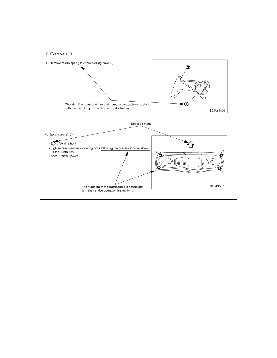
Relation between Illustrations and Descriptions
INFOID:0000000007359058
The following sample explains the relationship between the part description in an illustration, the part name in
the text and the service procedures.
Components
INFOID:0000000007359059
•
THE LARGE ILLUSTRATIONS
are exploded views (see the following) and contain tightening torques, lubri-
cation points, section number of the
PARTS CATALOG
(e.g. SEC. 440) and other information necessary to
perform repairs.
The illustrations should be used in reference to service matters only. When ordering parts, refer to the appro-
priate
PARTS CATALOG
.
Always check with the
PARTS DEPARMENT
for the latest parts information.
Components shown in an illustration may be identified by a circled number. When this style of illustration is
used, the text description of the components will follow the illustration.
SAIA0519E
August 2012
2012 Pathfinder
Нет комментариевНе стесняйтесь поделиться с нами вашим ценным мнением.
Текст