Nissan Pathfinder (2012 year). Instruction — part 106

BRC-114
< UNIT REMOVAL AND INSTALLATION >
[TYPE 1]
STEERING ANGLE SENSOR
STEERING ANGLE SENSOR
Removal and Installation
INFOID:0000000007356813
REMOVAL
1. Remove the spiral cable. Refer to
SR-7, "Removal and Installation"
2. Remove the screws and remove the steering angle sensor from the spiral cable.
INSTALLATION
Installation is in the reverse order of removal.
• Reset the neutral position of the steering angle sensor. Refer to
BRC-13, "CALIBRATION OF DECEL G
SENSOR : Special Repair Requirement"
.
CAUTION:
Any time the steering angle sensor is removed and installed or replaced, you must reset the neutral
position of the steering angle sensor. Refer to
BRC-13, "CALIBRATION OF DECEL G SENSOR : Special
.
August 2012
2012 Pathfinder
YAW RATE/SIDE/DECEL G SENSOR
BRC-115
< UNIT REMOVAL AND INSTALLATION >
[TYPE 1]
C
D
E
G
H
I
J
K
L
M
A
B
BRC
N
O
P
YAW RATE/SIDE/DECEL G SENSOR
Removal and Installation
INFOID:0000000007356814
REMOVAL
1. Remove the center console. Refer to
IP-22, "Removal and Installation"
.
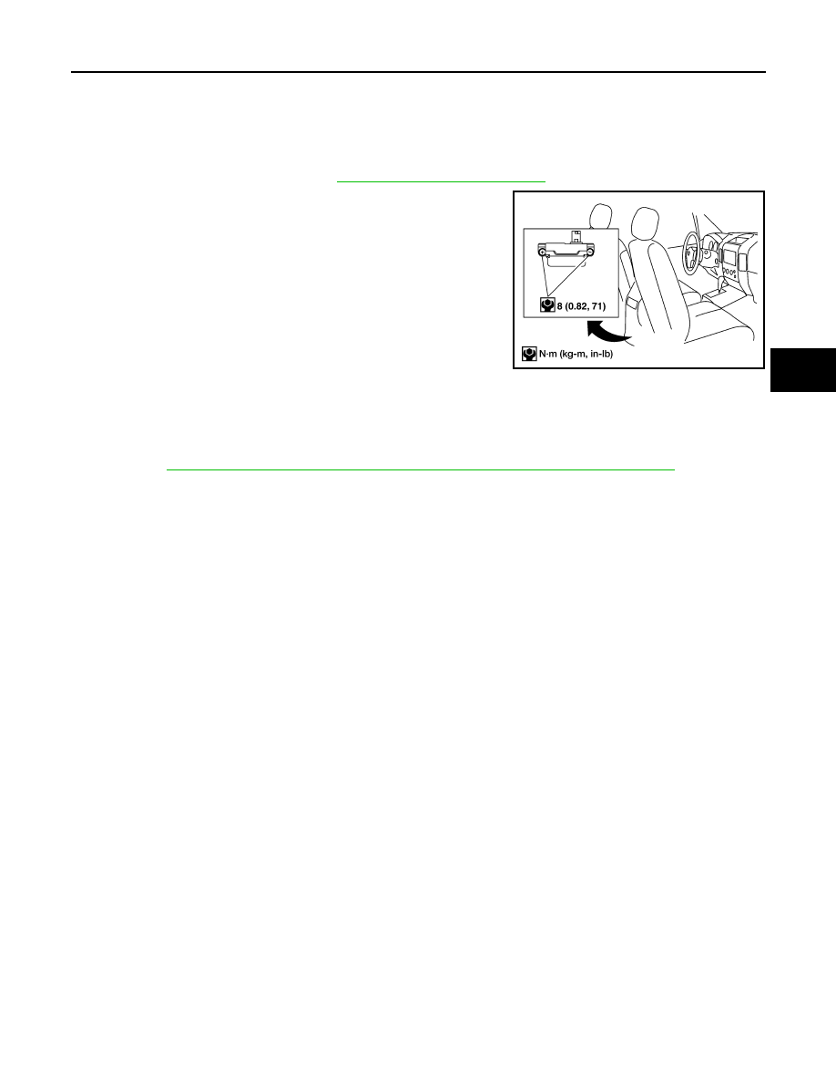
2. Remove the yaw rate/side/decel G sensor nuts as shown.
CAUTION:
• Do not use power tools to remove or install the yaw rate/
side/decel G sensor.
• Do not drop or strike the yaw rate/side/decel G sensor.
NOTE:
The location of the yaw rate/side/decel G sensor is the same for
all models.
3. Disconnect the yaw rate/side/decel G sensor connector and remove the yaw rate/side/decel G sensor.
INSTALLATION
Installation is in the reverse order of removal.
• After installing the yaw rate/side/decel G sensor, it is necessary to calibrate the yaw rate/side/decel G sen-
sor. Refer to
BRC-13, "CALIBRATION OF DECEL G SENSOR : Special Repair Requirement"
WFIA0230E
August 2012
2012 Pathfinder

BRC-116
< BASIC INSPECTION >
[TYPE 2]
APPLICATION NOTICE
BASIC INSPECTION
APPLICATION NOTICE
Application Notice
INFOID:0000000007818418
Service information
Remarks
TYPE 1
VDC/TCS/ABS (VQ40DE)
TYPE 2
VDC/TCS/ABS (VK56DE)
August 2012
2012 Pathfinder
DIAGNOSIS AND REPAIR WORKFLOW
BRC-117
< BASIC INSPECTION >
[TYPE 2]
C
D
E
G
H
I
J
K
L
M
A
B
BRC
N
O
P
DIAGNOSIS AND REPAIR WORKFLOW
Work Flow
INFOID:0000000007356816
PRECAUTIONS FOR DIAGNOSIS
If steering angle sensor, steering system parts, suspension system parts, ABS actuator and electric unit (con-
trol unit) or tires have been replaced, or if wheel alignment has been adjusted, be sure to adjust neutral posi-
tion of steering angle sensor before driving. Refer to
BRC-121, "ADJUSTMENT OF STEERING ANGLE
SENSOR NEUTRAL POSITION : Description"
August 2012
2012 Pathfinder
BRC-118
< BASIC INSPECTION >
[TYPE 2]
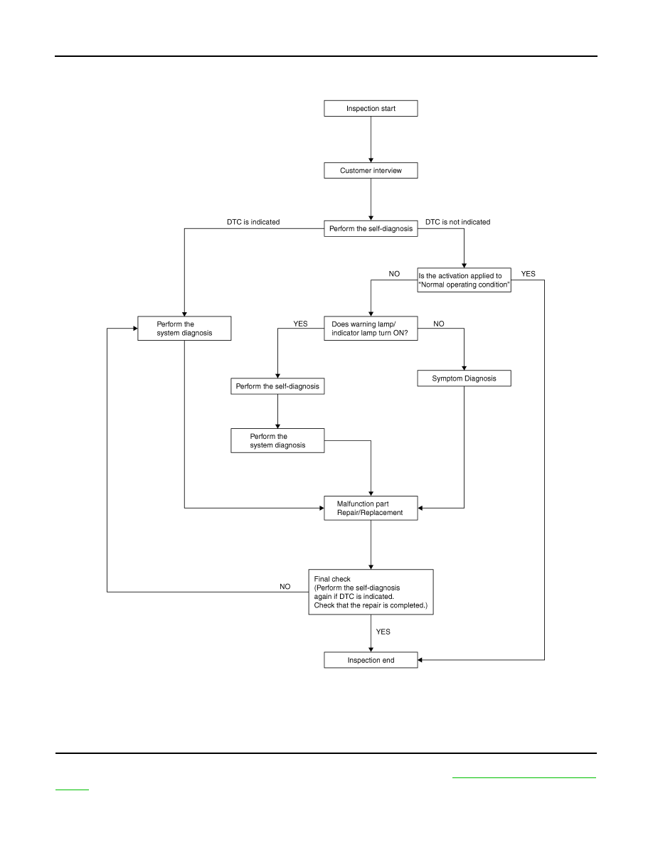
DIAGNOSIS AND REPAIR WORKFLOW
OVERALL SEQUENCE
DETAILED FLOW
1.
COLLECT THE INFORMATION FROM THE CUSTOMER
Get the detailed information from the customer about the symptom (the condition and the environment when
the incident/malfunction occurred) using the diagnosis worksheet. Refer to
JSFIA0010GB
August 2012
2012 Pathfinder

DIAGNOSIS AND REPAIR WORKFLOW
BRC-119
< BASIC INSPECTION >
[TYPE 2]
C
D
E
G
H
I
J
K
L
M
A
B
BRC
N
O
P
>> GO TO 2
2.
PERFORM THE SELF-DIAGNOSIS
Check the DTC display with the self-diagnosis function. Refer to
BRC-138, "CONSULT Function (ABS)"
Is there any DTC displayed?
YES
>> GO TO 3
NO
>> GO TO 4
3.
PERFORM THE SYSTEM DIAGNOSIS
Perform the diagnosis applicable to the displayed DTC. Refer to
.
>> GO TO 7
4.
CHECK THE SYMPTOM THAT IS NOT CONSIDERED A SYSTEM MALFUNCTION
Check that the symptom is a normal operation that is not considered a system malfunction. Refer to
Is the symptom a normal operation?
YES
>> Inspection End.
NO
>> GO TO 5
5.
CHECK THE WARNING LAMP AND INDICATOR LAMP FOR ILLUMINATION
Check that the warning lamp and indicator lamp illuminate.
• ABS warning lamp: Refer to
• Brake warning lamp: Refer to
• VDC OFF indicator lamp: Refer to
• SLIP indicator lamp: Refer to
Is ON/OFF timing normal?
YES
>> GO TO 6
NO
>> GO TO 2
6.
PERFORM THE DIAGNOSIS BY SYMPTOM
Perform the diagnosis applicable to the symptom.
>> GO TO 7
7.
REPAIR OR REPLACE THE MALFUNCTIONING PARTS
Repair or replace the specified malfunctioning parts.
>> GO TO 8
8.
FINAL CHECK
Perform the self-diagnosis again, and check that the malfunction is repaired completely. After checking, erase
the self-diagnosis memory. Refer to
BRC-138, "CONSULT Function (ABS)"
.
Is no other DTC present and the repair completed?
YES
>> Inspection End.
NO
>> GO TO 3
August 2012
2012 Pathfinder
BRC-120
< BASIC INSPECTION >
[TYPE 2]
DIAGNOSIS AND REPAIR WORKFLOW
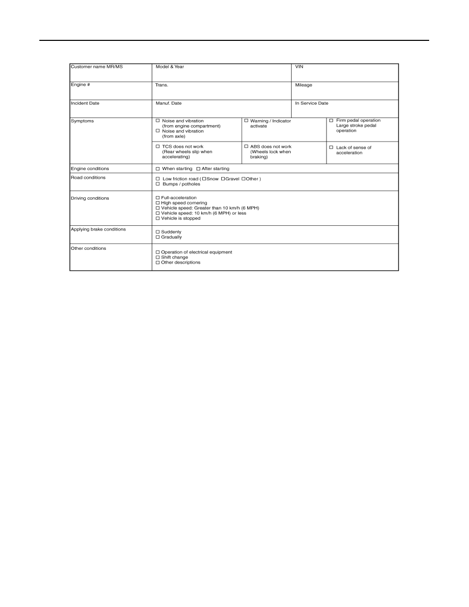
Diagnostic Work Sheet
INFOID:0000000007356817
SFIA3265E
August 2012
2012 Pathfinder

INSPECTION AND ADJUSTMENT
BRC-121
< BASIC INSPECTION >
[TYPE 2]
C
D
E
G
H
I
J
K
L
M
A
B
BRC
N
O
P
INSPECTION AND ADJUSTMENT
ADDITIONAL SERVICE WHEN REPLACING CONTROL UNIT
ADDITIONAL SERVICE WHEN REPLACING CONTROL UNIT : Description
INFOID:0000000007356818
After replacing the ABS actuator and electric unit (control unit), perform the following procedures:
• Neutral position adjustment for the steering angle sensor
• Calibration of the decel G sensor
ADDITIONAL SERVICE WHEN REPLACING CONTROL UNIT : Special Repair Re-
quirement
INFOID:0000000007356819
1.
PERFORM THE NEUTRAL POSITION ADJUSTMENT FOR THE STEERING ANGLE SENSOR
Perform the neutral position adjustment for the steering angle sensor.
>> Refer to
BRC-121, "ADJUSTMENT OF STEERING ANGLE SENSOR NEUTRAL POSITION :
, GO TO 2
2.
PERFORM CALIBRATION OF THE DECEL G SENSOR
Perform calibration of the decel G sensor.
>> Refer to
BRC-122, "CALIBRATION OF DECEL G SENSOR : Special Repair Requirement"
ADJUSTMENT OF STEERING ANGLE SENSOR NEUTRAL POSITION
ADJUSTMENT OF STEERING ANGLE SENSOR NEUTRAL POSITION : Description
INFOID:0000000007356820
Refer to the table below to determine if adjustment of steering angle sensor neutral position is required.
×
: Required –: Not required
ADJUSTMENT OF STEERING ANGLE SENSOR NEUTRAL POSITION : Special Re-
pair Requirement
INFOID:0000000007356821
ADJUSTMENT OF STEERING ANGLE SENSOR NEUTRAL POSITION
CAUTION:
To adjust neutral position of steering angle sensor, make sure to use CONSULT
(Adjustment cannot be done without CONSULT)
1.
ALIGN THE VEHICLE STATUS
Stop vehicle with front wheels in straight-ahead position.
Situation
Adjustment of steering angle sensor neutral position
Removing/Installing ABS actuator and electric unit (control unit)
—
Replacing ABS actuator and electric unit (control unit)
×
Removing/Installing steering angle sensor
×
Replacing steering angle sensor
×
Removing/Installing steering components
×
Replacing steering components
×
Removing/Installing suspension components
×
Replacing suspension components
×
Change tires to new ones
—
Tire rotation
—
Adjusting wheel alignment
×
Battery disconnection
×
August 2012
2012 Pathfinder
Нет комментариевНе стесняйтесь поделиться с нами вашим ценным мнением.
Текст