Nissan Pathfinder (2012 year). Instruction — part 406
FLUORESCENT LEAK DETECTOR
HA-29
< PERIODIC MAINTENANCE >
C
D
E
F
G
H
J
K
L
M
A
B
HA
N
O
P
FLUORESCENT LEAK DETECTOR
Checking of Refrigerant Leaks
INFOID:0000000007356310
PRELIMINARY CHECK
Perform a visual inspection of all refrigeration parts, fittings, hoses and components for signs of A/C oil leak-
age, damage, and corrosion. Any A/C oil leakage may indicate an area of refrigerant leakage. Allow extra
inspection time in these areas when using either an electronic refrigerant leak detector (J-41995) or fluores-
cent dye leak detector (J-42220).
If any dye is observed using a fluorescent dye leak detector (J-42220), confirm the leak using a electronic
refrigerant leak detector (J-41995). It is possible that the dye is from a prior leak that was repaired and not
properly cleaned.
When searching for leaks, do not stop when one leak is found but continue to check for additional leaks at all
system components and connections.
When searching for refrigerant leaks using an electronic refrigerant leak detector (J-41995), move the probe
along the suspected leak area at 25 - 50 mm (1 - 2 in) per second and no further than 6 mm (1/4 in) from the
component.
CAUTION:
Moving the electronic refrigerant leak detector probe slower and closer to the suspected leak area will
improve the chances of finding a leak.
Checking System for Leaks Using the Fluorescent Dye Leak Detector
INFOID:0000000007356311
1. Check the A/C system for leaks using the fluorescent dye leak detector and safety goggles (J-42220) in a
low sunlight area (area without windows preferable). Illuminate all components, fittings and lines. The dye
will appear as a bright green/yellow area at the point of leakage. Fluorescent dye observed at the evapo-
rator drain opening indicates an evaporator core assembly leak (tubes, core or expansion valve).
2. If the suspected area is difficult to see, use an adjustable mirror or wipe the area with a clean shop rag or
cloth, then inspect the shop rag or cloth with the fluorescent dye leak detector (J-42220) for dye residue.
3. After the leak is repaired, remove any residual dye using refrigerant dye cleaner (J-43872) to prevent
future misdiagnosis.
4. Perform a system performance check and then verify the leak repair using a electronic refrigerant leak
detector (J-41995).
NOTE:
• Other gases in the work area or substances on the A/C components, for example, anti-freeze, wind-
shield washer fluid, solvents and oils, may falsely trigger the leak detector. Make sure the surfaces to be
checked are clean.
• Clean with a dry cloth or blow off with shop air.
• Do not allow the sensor tip of the electronic refrigerant leak detector (J-41995) to contact with any sub-
stance. This can also cause false readings and may damage the detector.
Dye Injection
INFOID:0000000007356312
NOTE:
This procedure is only necessary when recharging the system or when the compressor has seized and must
be replaced.
1. Check the A/C system static (at rest) pressure. Pressure must be at least 345 kPa (3.52 kg/cm
2
, 50 psi).
2. Pour one bottle 7.4 cc (1/4 ounce) of the HFC-134a (R-134a) fluorescent leak detection dye (J-41447) into
the HFC-134a (R-134a) dye injector (J-41459).
CAUTION:
If repairing the A/C system or replacing a component, pour the HFC-134a (R-134a) fluorescent leak
detection dye (J-41447) directly into the open system connection and proceed with the service
procedures.
3. Connect the refrigerant dye injector (J-41459) to the low-pressure service valve.
4. Start the engine and switch the A/C system ON.
5. When the A/C system is operating (compressor running), inject one bottle 7.4 cc (1/4 ounce) of HFC-134a
(R-134a) fluorescent leak detection dye (J-41447) through the low-pressure service valve using HFC-
134a (R-134a) dye injector (J-41459). Refer to the manufacturer's operating instructions.
August 2012
2012 Pathfinder
HA-30
< PERIODIC MAINTENANCE >
FLUORESCENT LEAK DETECTOR
6. With the engine still running, disconnect the HFC-134a (R-134a) dye injector (J-41459) from the low-pres-
sure service valve.
7. Operate the A/C system for a minimum of 20 minutes to mix the HFC-134a (R-134a) fluorescent leak
detection dye (J-41447) with the A/C system oil. Depending on the leak size, operating conditions and
location of the leak, it may take from minutes to days for the HFC-134a (R-134a) fluorescent leak detec-
tion dye to penetrate an A/C system leak and become visible.
August 2012
2012 Pathfinder
ELECTRICAL LEAK DETECTOR
HA-31
< PERIODIC MAINTENANCE >
C
D
E
F
G
H
J
K
L
M
A
B
HA
N
O
P
ELECTRICAL LEAK DETECTOR
Checking of Refrigerant Leaks
INFOID:0000000007356313
PRELIMINARY CHECK
Perform a visual inspection of all refrigeration parts, fittings, hoses and components for signs of A/C oil leak-
age, damage, and corrosion. Any A/C oil leakage may indicate an area of refrigerant leakage. Allow extra
inspection time in these areas when using either an electronic refrigerant leak detector (J-41995) or fluores-
cent dye leak detector (J-42220).
If any dye is observed using a fluorescent dye leak detector (J-42220), confirm the leak using a electronic
refrigerant leak detector (J-41995). It is possible that the dye is from a prior leak that was repaired and not
properly cleaned.
When searching for leaks, do not stop when one leak is found but continue to check for additional leaks at all
system components and connections.
When searching for refrigerant leaks using an electronic refrigerant leak detector (J-41995), move the probe
along the suspected leak area at 25 - 50 mm (1 - 2 in) per second and no further than 6 mm (1/4 in) from the
component.
CAUTION:
Moving the electronic refrigerant leak detector probe slower and closer to the suspected leak area will
improve the chances of finding a leak.
Electronic Refrigerant Leak Detector
INFOID:0000000007356314
PRECAUTIONS FOR HANDLING LEAK DETECTOR
NOTE:
When performing a refrigerant leak check, use a electronic refrigerant leak detector (J-41995) or equivalent.
Ensure that the electronic refrigerant leak detector (J-41995) is calibrated and set properly according to the
manufacturer's operating instructions.
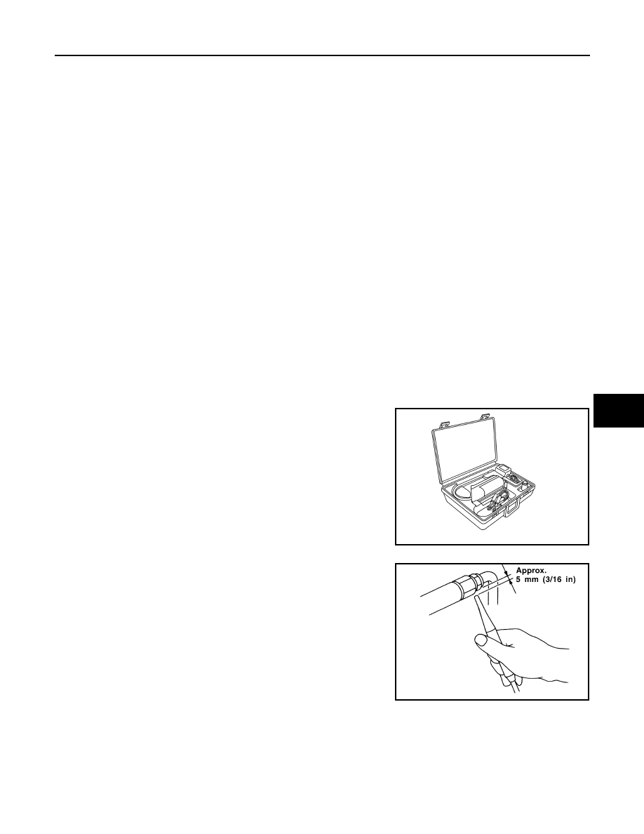
The electronic refrigerant leak detector (J-41995) is a delicate
device. To use the electronic refrigerant leak detector (J-41995)
properly, read the manufacturer's operating instructions and perform
any specified maintenance.
1. Position the probe approximately 5 mm (3/16 in) away from the
point to be checked as shown.
AHA281A
SHA707EA
August 2012
2012 Pathfinder
HA-32
< PERIODIC MAINTENANCE >
ELECTRICAL LEAK DETECTOR
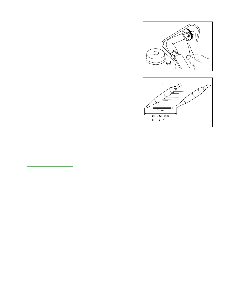
2. When checking for leaks, circle each fitting completely with the
probe as shown.
3. Move the probe along each component at a speed of approxi-
mately 25 - 50 mm (1 - 2 in)/second as shown.
CHECKING PROCEDURE
NOTE:
To prevent inaccurate or false readings, make sure there is no refrigerant vapor, shop chemicals, or cigarette
smoke in the vicinity of the vehicle. Perform the leak test in a calm area (low air/wind movement) so that the
leaking refrigerant is not dispersed.
1. Turn the engine OFF.
2. Connect the manifold gauge set (J-39183-C) to the A/C service ports. Refer to
.
3. Check if the A/C refrigerant pressure is at least 345 kPa (3.52 kg/cm
2
, 50 psi) above a temperature of
16
°
C (61
°
F). If less than specification, recover/evacuate and recharge the system with the specified
amount of refrigerant. Refer to
HA-36, "HFC-134a (R-134a) Service Procedure"
.
NOTE:
At temperatures below 16
°
C (61
°
F), leaks may not be detected since the system may not reach 345 kPa
(3.52 kg/cm
2
, 50 psi) pressure.
4. Perform the leak test from the high-pressure side (front A/C compressor discharge “a” to evaporator inlet
“f” or rear piping connection “l”) to the low-pressure side (front A/C evaporator drain hose “g” to shaft seal
“k” and rear A/C evaporator drain hose “o” to piping connection “r”). Refer to
. Clean
the component to be checked and carefully move the electronic refrigerant leak detector probe completely
around the following connections and components.
• Check the compressor shaft seal
• Check the high and low-pressure pipe and hose fittings, relief valve, and compressor shaft seal
• Check the liquid tank
• Check the refrigerant pressure sensor
• Check all around the service valves. Check that the service valve caps are screwed tightly on the ser-
vice valves (to prevent leaks).
NOTE:
After removing manifold gauge set (J-39183-C) from the service valves, wipe any residue from the ser-
vice valves to prevent any false readings by the electronic refrigerant leak detector (J-41995).
• Evaporator
With engine OFF, turn blower fan on “High” for at least 15 seconds to dissipate any refrigerant trace in
the heater and cooling unit assembly. Wait a minimum of 10 minutes accumulation time (refer to the
manufacturer's recommended procedure for actual wait time) before inserting the electronic refrigerant
leak detector probe into the heater and cooling unit assembly drain hose.
NOTE:
SHA706E
SHA708EA
August 2012
2012 Pathfinder
ELECTRICAL LEAK DETECTOR
HA-33
< PERIODIC MAINTENANCE >
C
D
E
F
G
H
J
K
L
M
A
B
HA
N
O
P
Keep the probe inserted for at least 10 seconds. Use caution not to contaminate the probe tip with water
or dirt that may be in the drain hose.
5. If a leak is detected, verify at least once by blowing compressed air into the area of the suspected leak,
then repeat the leak check.
6. Do not stop when one leak is found. Continue to check for additional leaks at all system components and
connections.
7. If no leaks are found, perform steps 8 - 11.
8. Start the engine.
9. Set the heater A/C controls as follows:
NOTE:
For the automatic system, turn OFF the automatic controls and set the heater A/C controls instructionly.
a. A/C switch to ON
b. Air flow to VENT mode
c. Intake position to RECIRCULATION mode
d. Temperature to MAX cold
e. Blower fan speed to HIGH
10. Run the engine at 1,500 rpm for at least 2 minutes.
11. Turn the engine OFF and perform the leak check again following
steps 4 through 6 above.
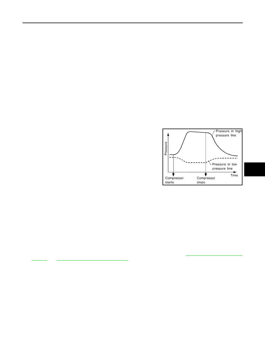
Refrigerant leaks should be checked immediately after turning
the engine OFF. Begin with the leak detector at the compressor.
The pressure on the high pressure side will gradually drop after
the refrigerant circulation stops and pressure on the low pres-
sure side will gradually rise, as shown in the graph. Some leaks
are more easily detected when the pressure is high.
12. Before connecting the recovery/recycling equipment to the vehicle, check the recovery/recycling equip-
ment gauges. No refrigerant pressure should be displayed. If pressure is displayed, recover the refriger-
ant from the equipment lines and then check the refrigerant purity.
13. Confirm refrigerant purity in supply tank using recovery/recycling equipment and refrigerant identifier
equipment (J-41810-NI).
14. Confirm the refrigerant purity in the vehicle's A/C system using recovery/recycling equipment and refriger-
ant identifier equipment (J-41810-NI).
15. Discharge the A/C system using recovery/recycling equipment. Repair the leaking fitting or component as
necessary.
16. Evacuate and recharge the A/C system and perform the leak test to confirm that there are no refrigerant
leaks.
17. Conduct the Operational Check to ensure system works properly. Refer to
HAC-6, "Operational Check (Rear)"
.
SHA839E
August 2012
2012 Pathfinder
HA-34
< REMOVAL AND INSTALLATION >
REFRIGERATION SYSTEM
REMOVAL AND INSTALLATION
REFRIGERATION SYSTEM
Component
INFOID:0000000007356315
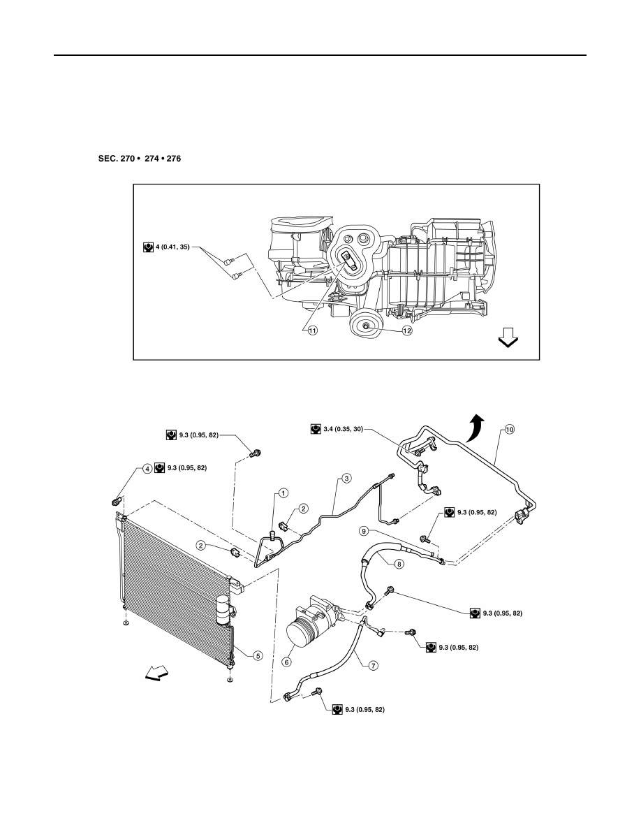
Front A/C Compressor and Condenser - VK56DE
AWIIA1537GB
August 2012
2012 Pathfinder
REFRIGERATION SYSTEM
HA-35
< REMOVAL AND INSTALLATION >
C
D
E
F
G
H
J
K
L
M
A
B
HA
N
O
P
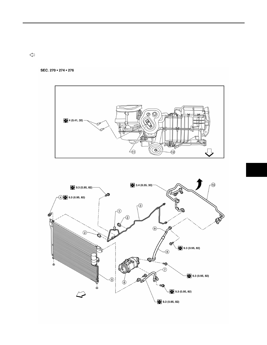
Front A/C Compressor and Condenser - VQ40DE
1.
High-pressure service valve
2.
Clip
3.
Front high-pressure A/C pipe
4.
Refrigerant pressure sensor
5.
Condenser and liquid tank assembly 6.
Compressor shaft seal
7.
Front high-pressure flexible A/C hose
8.
Front low-pressure flexible A/C hose 9.
Low-pressure service valve
10. Front low-pressure A/C pipe
11. Front expansion valve
12. Front A/C drain hose
Vehicle front
AWIIA1538GB
August 2012
2012 Pathfinder
HA-36
< REMOVAL AND INSTALLATION >
REFRIGERATION SYSTEM
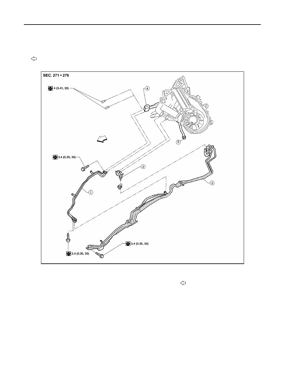
Rear A/C
CAUTION:
The new and former refrigerant connections use different O-ring configurations. Do not confuse O-
rings since they are not interchangeable. If a wrong O-ring is installed, refrigerant will leak at or
around the connection.
HFC-134a (R-134a) Service Procedure
INFOID:0000000007356316
SETTING OF SERVICE TOOLS AND EQUIPMENT
WARNING:
Avoid breathing A/C refrigerant and oil vapor or mist. Exposure may irritate eyes, nose and throat.
Remove HFC-134a (R-134a) refrigerant from the A/C system using certified service equipment meeting
requirements of SAE J2210 HFC-134a (R-134a) recycling equipment or SAE J2201 HFC-134a (R-134a)
1.
High-pressure service valve
2.
Clip
3.
Front high-pressure A/C pipe
4.
Refrigerant pressure sensor
5.
Condenser and liquid tank assembly 6.
Compressor shaft seal
7.
Front high-pressure flexible A/C hose
8.
Front low-pressure flexible A/C hose 9.
Low-pressure service valve
10. Front low-pressure A/C pipe
11. Front expansion valve
12. Front A/C drain hose
Vehicle front
AWIIA1539GB
1.
Rear high- and low-pressure A/C pipes
2.
Rear heater core hoses
3.
Underfloor rear high- and low-pres-
sure A/C and heater core pipes
4.
Rear expansion valve
5.
Rear drain hose
Vehicle front
August 2012
2012 Pathfinder
Нет комментариевНе стесняйтесь поделиться с нами вашим ценным мнением.
Текст