Nissan Pathfinder (2012 year). Instruction — part 233
REAR FINAL DRIVE
DLN-429
< UNIT DISASSEMBLY AND ASSEMBLY >
[REAR FINAL DRIVE: R200]
C
E
F
G
H
I
J
K
L
M
A
B
DLN
N
O
P
UNIT DISASSEMBLY AND ASSEMBLY
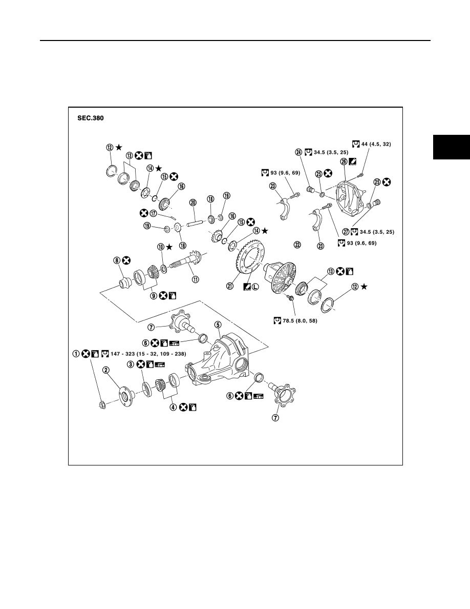
REAR FINAL DRIVE
Exploded View
INFOID:0000000007357650
1.
Drive pinion lock nut
2.
Companion flange
3.
Front oil seal
4.
Drive pinion front bearing
5.
Gear carrier
6.
Side oil seal
7.
Side flange
8.
Collapsible spacer
9.
Drive pinion rear bearing
10. Drive pinion height adjusting
washer
11. Drive pinion
12. Side bearing adjusting washer
13. Side bearing
14. Side gear thrust washer
15. Circular clip
16. Side gear
17. Lock pin
18. Pinion mate gear
19. Pinion mate thrust washer
20. Pinion mate shaft
21. Drive gear
22. Differential case
23. Side bearing cap
24. Filler plug
25. Gasket
26. Carrier cover
27. Drain plug
WDIA0295E
August 2012
2012 Pathfinder
DLN-430
< UNIT DISASSEMBLY AND ASSEMBLY >
[REAR FINAL DRIVE: R200]
REAR FINAL DRIVE
Disassembly and Assembly
INFOID:0000000007357651
ASSEMBLY INSPECTION AND ADJUSTMENT
• Drain the differential gear oil before inspection and adjustment. Refer to
DLN-420, "Changing Differential
• Remove and install the carrier cover as necessary for inspection and adjustment. Refer to
Total Preload Torque
1. Remove the side flanges if necessary. Refer to
DLN-423, "Removal and Installation"
.
CAUTION:
The side flanges shaft must be removed in order to measure total preload torque.
2. Rotate the drive pinion back and forth 2 to 3 times to check for unusual noise and rotation malfunction.
3. Rotate the drive pinion at least 20 times to check for smooth operation of the bearings.
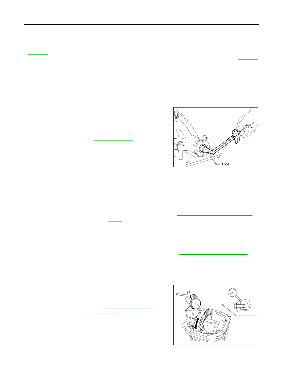
4. Measure total preload torque using Tool.
NOTE:
Total preload torque = Drive pinion bearing preload torque +
Side bearing preload torque
• If the measured value is out of the specification, check and adjust each part. Adjust the drive pinion
bearing preload torque first, then adjust the side bearing preload torque.
CAUTION:
Select a side bearing adjusting washer for right and left individually.
Drive Gear Runout
1. Fit a dial indicator to the drive gear back face.
2. Rotate the drive gear to measure runout.
• If the runout is outside of the limit, check the condition of the drive
gear assembly. Foreign material may be caught between the drive
gear and differential case, or the differential case or drive gear may
be deformed.
CAUTION:
Replace drive gear and drive pinion as a set.
Tool number
: ST3127S000 (J-25765-A)
Total preload torque:
SPD884
If the total preload torque is greater than specification
On drive pinion bearings: Replace the collapsible spacer.
On side bearings:
Use thinner side bearing adjusting washers by the same
amount on each side. Refer to
DLN-447, "Inspection and Adjust-
If the total preload torque is less than specification
On drive pinion bearings: Tighten the drive pinion lock nut.
On side bearings:
Use thicker side bearing adjusting washers by the same
amount on each side. Refer to
.
Runout limit
Refer to
SPD886
August 2012
2012 Pathfinder
REAR FINAL DRIVE
DLN-431
< UNIT DISASSEMBLY AND ASSEMBLY >
[REAR FINAL DRIVE: R200]
C
E
F
G
H
I
J
K
L
M
A
B
DLN
N
O
P
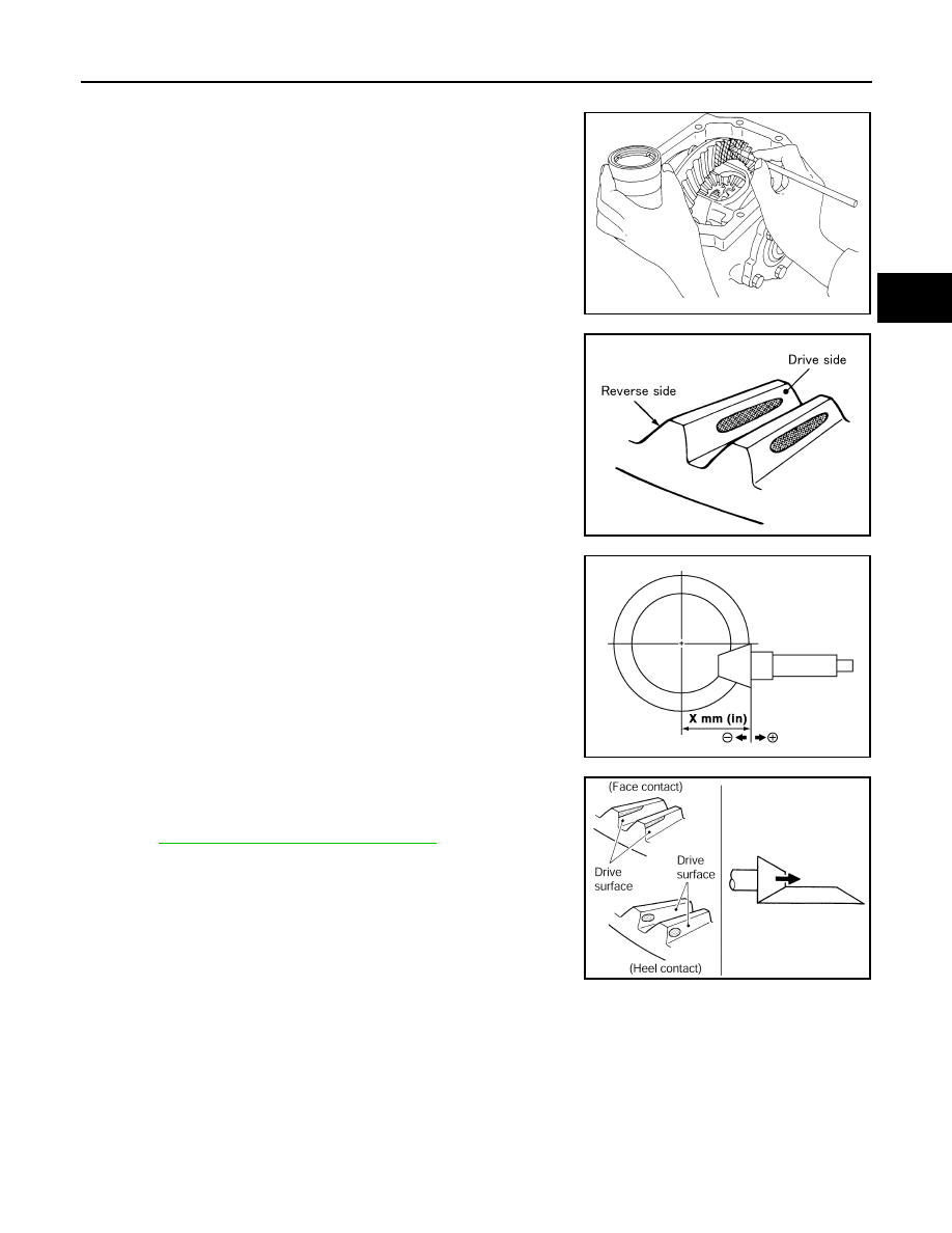
Tooth Contact
1. Apply red lead to the drive gear.
NOTE:
Apply red lead to both faces of three to four gears, at four loca-
tions evenly spaced on the drive gear.
2. Rotate the drive gear back and forth several times. Then check
for correct drive pinion to drive gear tooth contact as shown.
CAUTION:
Check tooth contact on drive side and reverse side.
3. If the tooth contact is improperly adjusted, follow the procedure
below to adjust the pinion height (dimension X).
• If the tooth contact is near the face (face contact), or near the heel
(heel contact), use a thicker drive pinion height adjusting washers
to move the drive pinion closer to the drive gear.
DLN-447, "Inspection and Adjustment"
SPD357
SDIA0570E
SDIA0517E
PDIA0440E
August 2012
2012 Pathfinder
DLN-432
< UNIT DISASSEMBLY AND ASSEMBLY >
[REAR FINAL DRIVE: R200]
REAR FINAL DRIVE
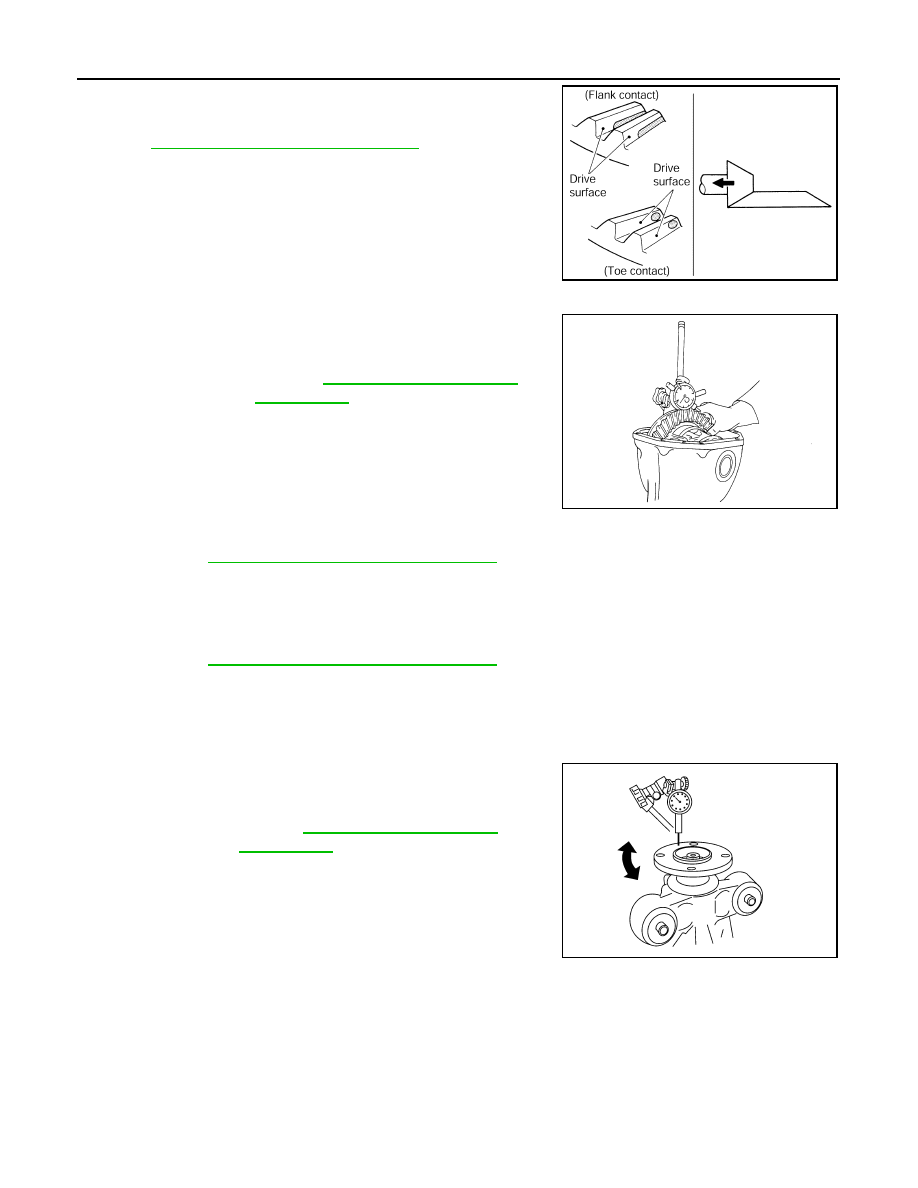
• If the tooth contact is near the flank (flank contact), or near the toe
(toe contact), use a thinner drive pinion height adjusting washers to
move the drive pinion farther from the drive gear.
DLN-447, "Inspection and Adjustment"
Backlash
1. Fit a dial indicator to the drive gear face to measure the back-
lash.
• If the backlash is outside of the specification, change the thickness
of the side bearing adjusting washers.
CAUTION:
Do not change the total thickness of side bearing adjusting washers as it will change the side bearing
preload torque.
Companion Flange Runout
1. Rotate companion flange and check for runout on the outer face
of the companion flange using suitable tool.
2. If the runout is outside of the runout limit, follow the procedure
below to adjust.
a. Rotate the companion flange on the drive pinion by 90
°
, 180
°
and 270
°
while checking for the position where the runout is
minimum.
b. If the runout is still outside of the runout limit after the companion
flange has been rotated on the drive pinion, possible cause could be an assembly malfunction of drive pin-
ion and drive pinion bearing or a malfunctioning drive pinion bearing.
c.
If the runout is still outside of the runout limit after repair of the assembly of drive pinion and drive pinion
bearing or drive pinion bearing, replace the companion flange.
DISASSEMBLY
Side Flange
1. Drain the differential gear oil if necessary.
PDIA0441E
Backlash:
Refer to
If the backlash is greater than specification:
Make side bearing adjusting washer thicker on drive
gear back side, and side bearing adjusting washer
thinner on drive gear tooth side by the same amount.
Refer to
DLN-447, "Inspection and Adjustment"
.
If the backlash is less than specification:
Make side bearing adjusting washer thinner on drive
gear back side, and side bearing adjusting washer
thicker on drive gear tooth side by the same amount.
Refer to
DLN-447, "Inspection and Adjustment"
.
SPD513
Runout limit
Refer to
WDIA0231E
August 2012
2012 Pathfinder
REAR FINAL DRIVE
DLN-433
< UNIT DISASSEMBLY AND ASSEMBLY >
[REAR FINAL DRIVE: R200]
C
E
F
G
H
I
J
K
L
M
A
B
DLN
N
O
P
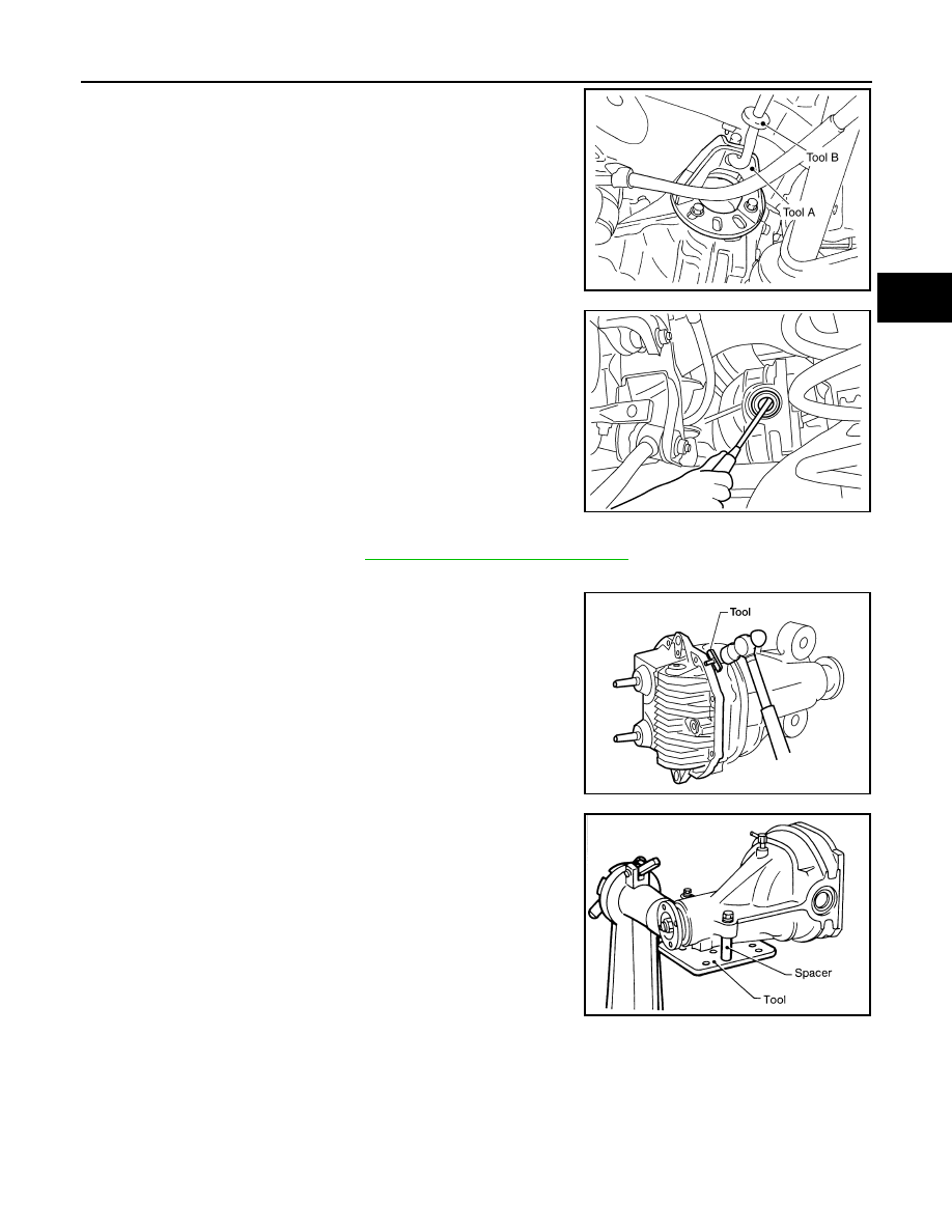
2. Remove the side flange using Tools.
NOTE:
Circular clip installation position: Rear final drive side
3. Remove the side oil seal using suitable tool.
CAUTION:
Do not to damage gear carrier.
Differential Assembly
1. Remove the side flanges. Refer to
DLN-423, "Removal and Installation"
.
2. Remove the carrier cover bolts.
3. Remove the carrier cover bolts and separate the carrier cover
from the gear carrier using Tool.
CAUTION:
• Do not damage the mating surface.
• Do not insert flat-bladed screwdriver, this will damage the
mating surface.
4. Mount the carrier on the Tool using two 45 mm (1.77 in) spacers.
Tool numbers
(A): KV40104100 ( — )
(B): ST36230000 (J-25840-A)
WDIA0115E
SDIA0495E
Tool number
: KV10111100 (J-37228)
WDIA0123E
Tool number
: KV38100800 (J-25604-01)
SPD888
August 2012
2012 Pathfinder
DLN-434
< UNIT DISASSEMBLY AND ASSEMBLY >
[REAR FINAL DRIVE: R200]
REAR FINAL DRIVE
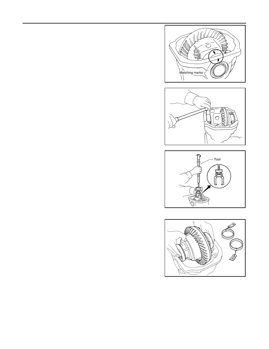
5. For proper reinstallation, paint matching marks on one side of
the side bearing cap and gear carrier.
CAUTION:
• For matching marks, use paint. Do not damage side bear-
ing cap or gear carrier.
• Side bearing caps are line-board during manufacture. The
matching marks are used to reinstall them in their original
positions.
6. Remove the side bearing caps.
7. Lift the differential case assembly out using Tool.
CAUTION:
• Keep side bearing outer races together with inner race.
Do not mix them up.
• Keep side bearing adjusting washers together with side
bearings.
SDIA1795E
S-PD343
Tool number
: HT72400000 ( — )
S-PD344
SPD919
August 2012
2012 Pathfinder
REAR FINAL DRIVE
DLN-435
< UNIT DISASSEMBLY AND ASSEMBLY >
[REAR FINAL DRIVE: R200]
C
E
F
G
H
I
J
K
L
M
A
B
DLN
N
O
P
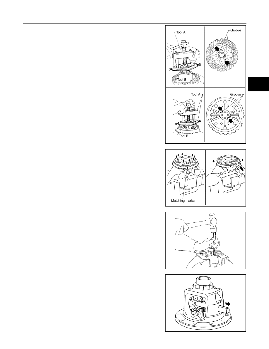
8. Remove the side bearing inner races using Tools.
CAUTION:
• Engage Tool jaws in bearing groove to prevent damage.
• Place copper plates between the side bearing and drive
gear and the vise to prevent damage.
• Do not remove side bearing inner race unless it is being
replaced.
9. For proper reinstallation, paint matching marks on the differential
case and drive gear.
CAUTION:
Use paint for matching marks. Do not damage differential
case or drive gear.
10. Remove the drive gear bolts.
11. Tap the drive gear off the differential case using suitable tool.
CAUTION:
Tap evenly all around to keep drive gear from bending.
12. Remove the lock pin of the pinion mate shaft from the drive gear
side using suitable tool.
13. Remove the pinion mate shaft.
Tool number
(A): ST33051001 (J-22888-20)
(B): ST33061000 (J-8107-2)
SPD920
PDIA0496E
WDIA0132E
SDIA0031J
August 2012
2012 Pathfinder
DLN-436
< UNIT DISASSEMBLY AND ASSEMBLY >
[REAR FINAL DRIVE: R200]
REAR FINAL DRIVE
14. Turn the pinion mate gear, then remove the pinion mate gear,
pinion mate thrust washer, side gear and side gear thrust
washer from the differential case.
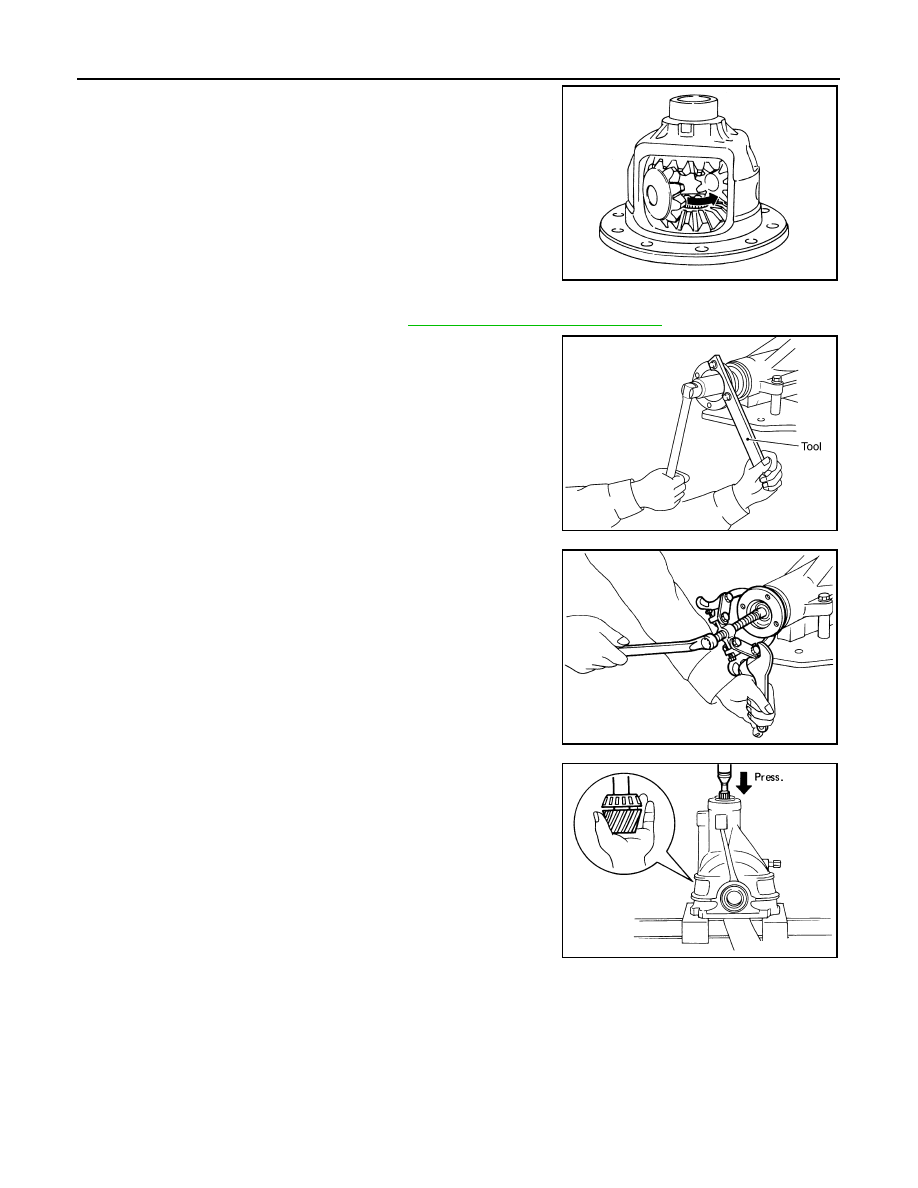
Drive Pinion Assembly
1. Remove the differential assembly. Refer to
DLN-426, "Removal and Installation"
.
2. Remove the drive pinion lock nut using suitable tool.
3. Put matching marks on the companion flange and drive pinion
using paint.
CAUTION:
Use paint to make the matching marks. Do not damage the
companion flange or drive pinion.
4. Remove the companion flange using suitable tool.
5. Press the drive pinion assembly (with rear inner bearing race
and collapsible spacer) out of the gear carrier.
CAUTION:
Do not drop drive pinion assembly.
6. Remove the front oil seal.
CAUTION:
Do not damage gear carrier.
7. Remove the drive pinion front bearing inner race.
SDIA0032J
SDIA1144E
SDIA1132E
SPD892
August 2012
2012 Pathfinder
Нет комментариевНе стесняйтесь поделиться с нами вашим ценным мнением.
Текст