Nissan Pathfinder (2012 year). Instruction — part 154
BCM (BODY CONTROL MODULE)
DLK-127
< ECU DIAGNOSIS INFORMATION >
[WITH INTELLIGENT KEY SYSTEM]
C
D
E
F
G
H
I
J
L
M
A
B
DLK
N
O
P
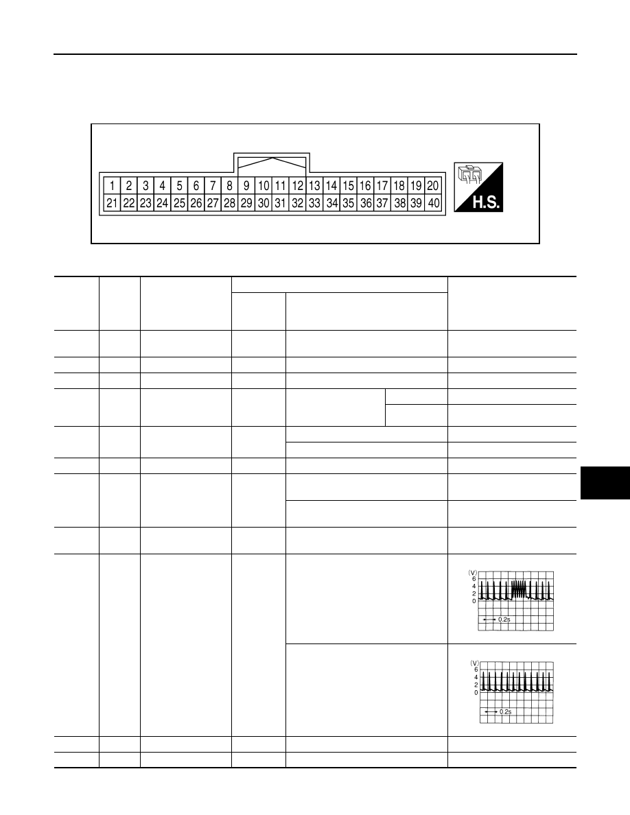
19
V
Remote keyless entry
receiver (power sup-
ply)
Output
OFF
Ignition switch OFF
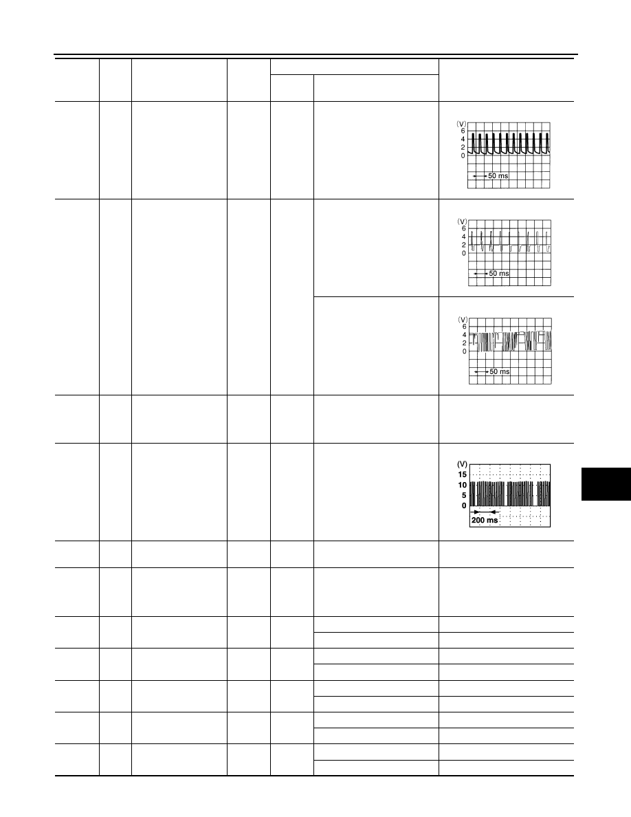
20
G
Remote keyless entry
receiver (signal)
Input
OFF
Stand-by (keyfob buttons re-
leased)
When remote keyless entry
receiver receives signal from
keyfob (keyfob buttons
pressed)
21
GR
NATS antenna amp.
Input
OFF
→
ON
Ignition switch (OFF
→
ON)
Just after turning ignition switch
ON: Pointer of tester should
move for approx. 1 second, then
return to battery voltage.
22
V
BUS
—
—
Ignition switch ON or power
window timer operates
23
G
Security indicator
lamp
Output
OFF
Goes OFF
→
illuminates (Ev-
ery 2.4 seconds)
Battery voltage
→
0V
25
BR
NATS antenna amp.
Input
OFF
→
ON
Ignition switch (OFF
→
ON)
Just after turning ignition switch
ON: Pointer of tester should
move for approx. 1 second, then
return to battery voltage.
27
W
Compressor ON sig-
nal
Input
ON
A/C switch OFF
5V
A/C switch ON
0V
28
R
Front blower monitor
Input
ON
Front blower motor OFF
Battery voltage
Front blower motor ON
0V
29
G
Hazard switch
Input
OFF
ON
0V
OFF
5V
30
1
G
Back door opener
switch
Input
OFF
ON (open)
0V
OFF (closed)
Battery voltage
30
2
SB
Back door opener
switch
Input
OFF
ON (open)
0V
OFF (closed)
Battery voltage
Terminal
Wire
color
Signal name
Signal
input/
output
Measuring condition
Reference value or waveform
(Approx.)
Ignition
switch
Operation or condition
LIIA1893E
LIIA1894E
LIIA1895E
PIIA2344E
August 2012
2012 Pathfinder
2012 Pathfinder
DLK-128
< ECU DIAGNOSIS INFORMATION >
[WITH INTELLIGENT KEY SYSTEM]
BCM (BODY CONTROL MODULE)
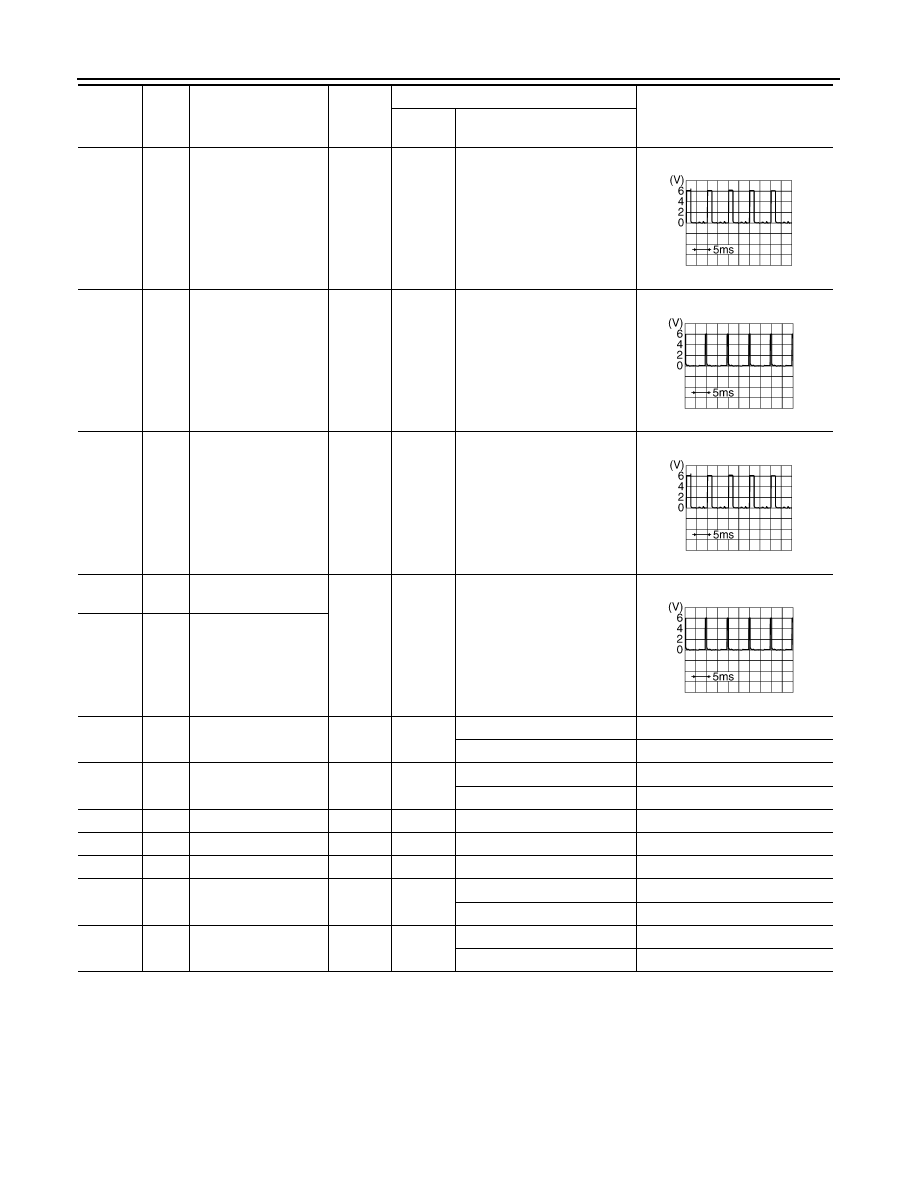
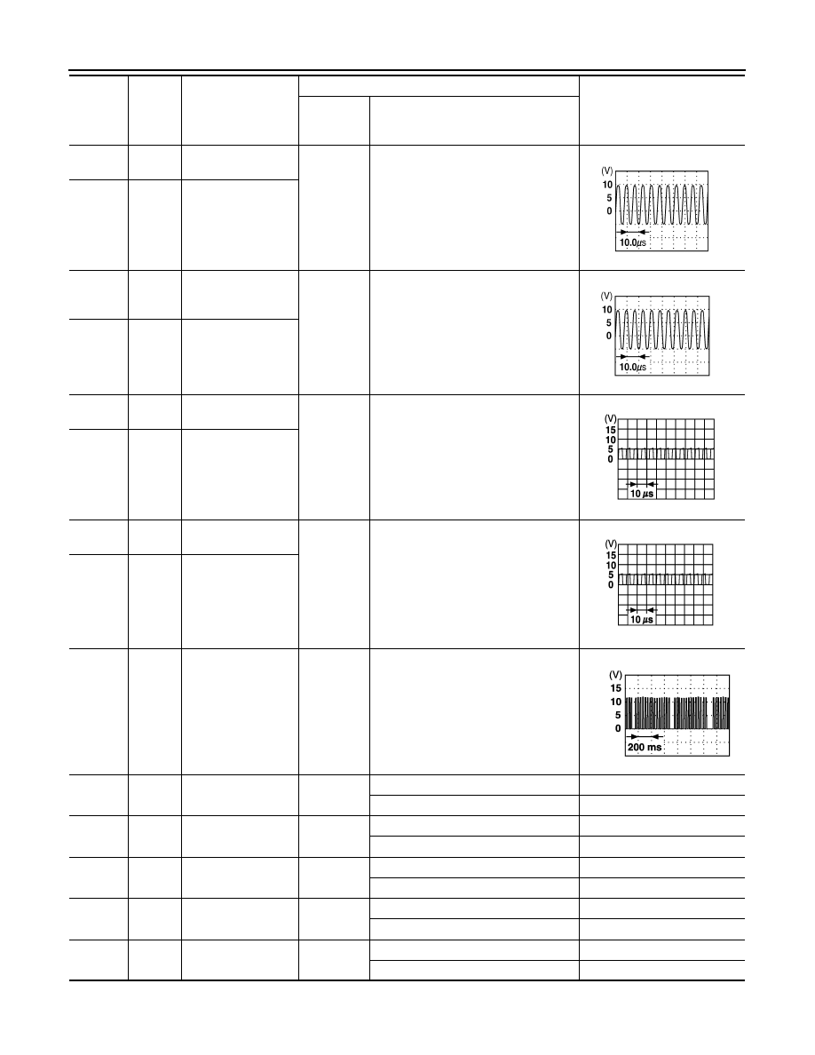
32
O
Combination switch
output 5
Output
ON
Lighting, turn, wiper OFF
Wiper dial position 4
33
GR
Combination switch
output 4
Output
ON
Lighting, turn, wiper OFF
Wiper dial position 4
34
G
Combination switch
output 3
Output
ON
Lighting, turn, wiper OFF
Wiper dial position 4
35
BR
Combination switch
output 2
Output
ON
Lighting, turn, wiper OFF
Wiper dial position 4
36
LG
Combination switch
output 1
37
1
B
Key switch and key
lock solenoid
Input
OFF
Key inserted
Battery voltage
Key inserted
0V
37
2
B
Key switch and igni-
tion knob switch
Input
OFF
Intelligent Key inserted
Battery voltage
Intelligent Key inserted
0V
38
W/R
Ignition switch (ON)
Input
ON
—
Battery voltage
39
L
CAN-H
—
—
—
—
40
P
CAN-L
—
—
—
—
42
LG
Glass hatch ajar
switch
Input
ON
Glass hatch open
0V
Glass hatch closed
Battery voltage
43
P
Back door latch switch
Input
OFF
ON (open)
0V
OFF (closed)
Battery voltage
Terminal
Wire
color
Signal name
Signal
input/
output
Measuring condition
Reference value or waveform
(Approx.)
Ignition
switch
Operation or condition
SKIA5291E
SKIA5292E
SKIA5291E
SKIA5292E
August 2012
2012 Pathfinder
2012 Pathfinder
BCM (BODY CONTROL MODULE)
DLK-129
< ECU DIAGNOSIS INFORMATION >
[WITH INTELLIGENT KEY SYSTEM]
C
D
E
F
G
H
I
J
L
M
A
B
DLK
N
O
P
44
O
Rear wiper auto stop
switch
Input
ON
Rise up position (rear wiper
arm on stopper)
0V
A Position (full clockwise stop
position)
Battery voltage
Forward sweep (counterclock-
wise direction)
Fluctuating
B Position (full counterclock-
wise stop position)
0V
Reverse sweep (clockwise di-
rection)
Fluctuating
47
GR
Front door switch LH
Input
OFF
ON (open)
0V
OFF (closed)
Battery voltage
48
P
Rear door switch LH
Input
OFF
ON (open)
0V
OFF (closed)
Battery voltage
49
L
Cargo lamp
Output
OFF
Any door open (ON)
0V
All doors closed (OFF)
Battery voltage
51
O
Trailer turn signal
(right)
Output
ON
Turn right ON
52
LG
Trailer turn signal (left)
Output
ON
Turn left ON
53
L
Back door latch actua-
tor
Output
OFF
OFF
0
ON
Battery voltage
55
W
Rear wiper output cir-
cuit 1
Output
ON
OFF
0
ON
Battery voltage
56
R/Y
Battery saver output
Output
OFF
15 minutes (early production)
or 10 minutes (late production)
after ignition switch is turned
OFF
0V
ON
—
Battery voltage
57
R/Y
Battery power supply
Input
OFF
—
Battery voltage
58
W
Optical sensor
Input
ON
When optical sensor is illumi-
nated
3.1V or more
When optical sensor is not illu-
minated
0.6V or less
59
GR
Front door lock as-
sembly LH actuator
(unlock)
Output
OFF
OFF (neutral)
0V
ON (unlock)
Battery voltage
Terminal
Wire
color
Signal name
Signal
input/
output
Measuring condition
Reference value or waveform
(Approx.)
Ignition
switch
Operation or condition
SKIA3009J
SKIA3009J
August 2012
2012 Pathfinder
2012 Pathfinder
DLK-130
< ECU DIAGNOSIS INFORMATION >
[WITH INTELLIGENT KEY SYSTEM]
BCM (BODY CONTROL MODULE)
1: With remote keyless entry system
2: With Intelligent Key system
Fail Safe
INFOID:0000000007818281
Fail-safe index
BCM performs fail-safe control when any DTC listed below is detected.
DTC Inspection Priority Chart
INFOID:0000000007818282
If some DTCs are displayed at the same time, perform inspections one by one based on the following priority
chart.
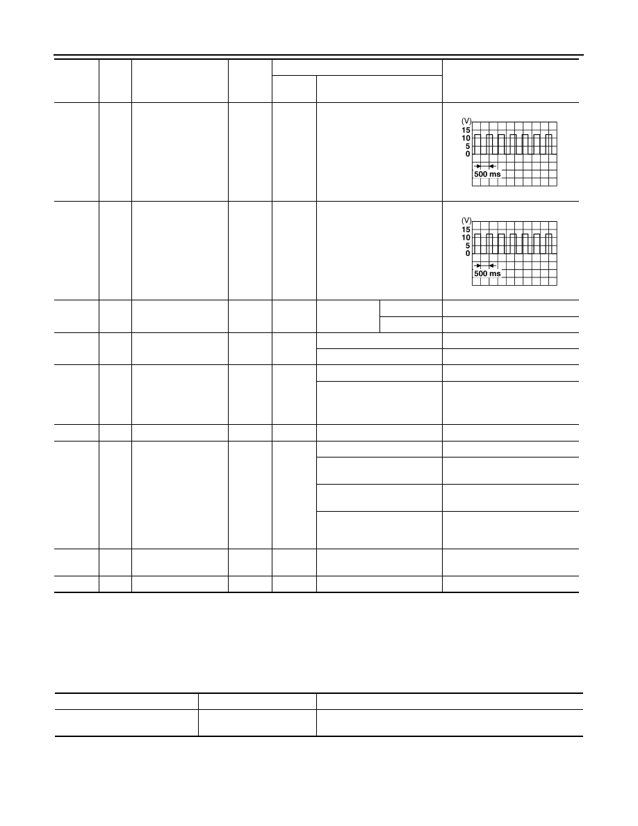
60
LG
Turn signal (left)
Output
ON
Turn left ON
61
G
Turn signal (right)
Output
ON
Turn right ON
63
BR
Interior room/map
lamp
Output
OFF
Any door
switch
ON (open)
0V
OFF (closed)
Battery voltage
65
V
All door lock actuators
(lock)
Output
OFF
OFF (neutral)
0V
ON (lock)
Battery voltage
66
L
Front door lock actua-
tor RH, rear door lock
actuators LH/RH and
glass hatch lock actu-
ator (unlock)
Output
OFF
OFF (neutral)
0V
ON (unlock)
Battery voltage
67
B
Ground
Input
ON
—
0V
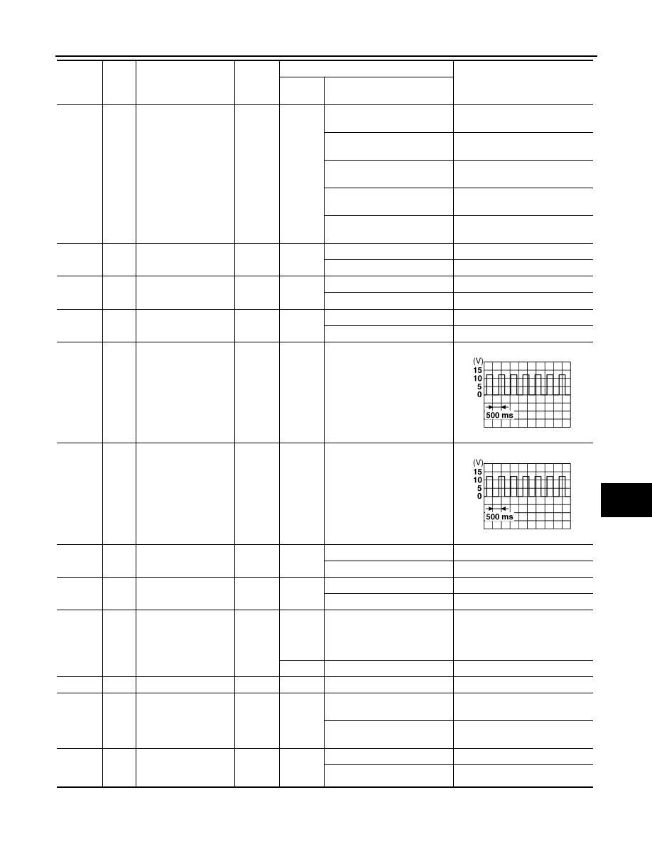
68
W/R
Power window power
supply (RAP)
Output
—
Ignition switch ON
Battery voltage
Within 45 seconds after igni-
tion switch OFF
Battery voltage
More than 45 seconds after ig-
nition switch OFF
0V
When front door LH or RH is
open or power window timer
operates
0V
69
L
Power window power
supply
Output
—
—
Battery voltage
70
W
Battery power supply
Input
OFF
—
Battery voltage
Terminal
Wire
color
Signal name
Signal
input/
output
Measuring condition
Reference value or waveform
(Approx.)
Ignition
switch
Operation or condition
SKIA3009J
SKIA3009J
Display contents of CONSULT
Fail-safe
Cancellation
U1000: CAN COMM CIRCUIT
Inhibit engine cranking
When the BCM re-establishes communication with the other mod-
ules.
August 2012
2012 Pathfinder
2012 Pathfinder

BCM (BODY CONTROL MODULE)
DLK-131
< ECU DIAGNOSIS INFORMATION >
[WITH INTELLIGENT KEY SYSTEM]
C
D
E
F
G
H
I
J
L
M
A
B
DLK
N
O
P
DTC Index
INFOID:0000000007818283
NOTE:
Details of time display
• CRNT: Displays when there is a malfunction now or after returning to the normal condition until turning igni-
tion switch OFF
→
ON again.
• 1 - 39: Displayed if any previous malfunction is present when current condition is normal. It increases like 1
→
2
→
3...38
→
39 after returning to the normal condition whenever ignition switch OFF
→
ON. The counter
remains at 39 even if the number of cycles exceeds it. It is counted from 1 again when turning ignition switch
OFF
→
ON after returning to the normal condition if the malfunction is detected again.
Priority
DTC
1
• U1000: CAN COMM CIRCUIT
2
• B2190: NATS ANTENNA AMP
• B2191: DIFFERENCE OF KEY
• B2192: ID DISCORD BCM-ECM
• B2193: CHAIN OF BCM-ECM
• B2013: STRG COMM 1
• B2552: INTELLIGENT KEY
• B2590: NATS MALFUNCTION
3
• C1729: VHCL SPEED SIG ERR
• C1735: IGNITION SIGNAL
4
• C1704: LOW PRESSURE FL
• C1705: LOW PRESSURE FR
• C1706: LOW PRESSURE RR
• C1707: LOW PRESSURE RL
• C1708: [NO DATA] FL
• C1709: [NO DATA] FR
• C1710: [NO DATA] RR
• C1711: [NO DATA] RL
• C1712: [CHECKSUM ERR] FL
• C1713: [CHECKSUM ERR] FR
• C1714: [CHECKSUM ERR] RR
• C1715: [CHECKSUM ERR] RL
• C1716: [PRESSDATA ERR] FL
• C1717: [PRESSDATA ERR] FR
• C1718: [PRESSDATA ERR] RR
• C1719: [PRESSDATA ERR] RL
• C1720: [CODE ERR] FL
• C1721: [CODE ERR] FR
• C1722: [CODE ERR] RR
• C1723: [CODE ERR] RL
• C1724: [BATT VOLT LOW] FL
• C1725: [BATT VOLT LOW] FR
• C1726: [BATT VOLT LOW] RR
• C1727: [BATT VOLT LOW] RL
CONSULT display
Fail-safe
Intelligent Key
warning lamp ON
Low tire pressure
warning lamp ON
Reference page
No DTC is detected.
Further testing may be required.
—
—
—
—
U1000: CAN COMM CIRCUIT
X
—
—
B2013: STRG COMM 1
—
—
—
B2190: NATS ANTENNA AMP
—
—
—
(with I-Key)
(without I-
Key)
B2191: DIFFERENCE OF KEY
—
—
—
(with I-Key)
(without I-
Key)
August 2012
2012 Pathfinder
2012 Pathfinder

DLK-132
< ECU DIAGNOSIS INFORMATION >
[WITH INTELLIGENT KEY SYSTEM]
BCM (BODY CONTROL MODULE)
B2192: ID DISCORD BCM-ECM
—
—
—
(with I-Key)
(without I-
Key)
B2193: CHAIN OF BCM-ECM
—
—
—
(with I-Key)
(without I-
Key)
B2552: INTELLIGENT KEY
—
—
—
B2590: NATS MALFUNCTION
—
—
—
C1708: [NO DATA] FL
—
—
X
C1709: [NO DATA] FR
—
—
X
C1710: [NO DATA] RR
—
—
X
C1711: [NO DATA] RL
—
—
X
C1712: [CHECKSUM ERR] FL
—
—
X
C1713: [CHECKSUM ERR] FR
—
—
X
C1714: [CHECKSUM ERR] RR
—
—
X
C1715: [CHECKSUM ERR] RL
—
—
X
C1716: [PRESSDATA ERR] FL
—
—
X
C1717: [PRESSDATA ERR] FR
—
—
X
C1718: [PRESSDATA ERR] RR
—
—
X
C1719: [PRESSDATA ERR] RL
—
—
X
C1720: [CODE ERR] FL
—
—
X
C1721: [CODE ERR] FR
—
—
X
C1722: [CODE ERR] RR
—
—
X
C1723: [CODE ERR] RL
—
—
X
C1724: [BATT VOLT LOW] FL
—
—
X
C1725: [BATT VOLT LOW] FR
—
—
X
C1726: [BATT VOLT LOW] RR
—
—
X
C1727: [BATT VOLT LOW] RL
—
—
X
C1729: VHCL SPEED SIG ERR
—
—
X
C1735: IGNITION SWITCH
—
—
X
CONSULT display
Fail-safe
Intelligent Key
warning lamp ON
Low tire pressure
warning lamp ON
Reference page
August 2012
2012 Pathfinder
2012 Pathfinder
INTELLIGENT KEY UNIT
DLK-133
< ECU DIAGNOSIS INFORMATION >
[WITH INTELLIGENT KEY SYSTEM]
C
D
E
F
G
H
I
J
L
M
A
B
DLK
N
O
P
INTELLIGENT KEY UNIT
Reference Value - Intelligent Key Unit
INFOID:0000000007355515
TERMINAL LAYOUT
PHYSICAL VALUES
WIIA1168E
Terminal
Wire
Color
Item
Condition
Voltage (V)
Approx.
Ignition
Switch Po-
sition
Operation or Conditions
1
O
Steering lock sole-
noid power supply
LOCK
—
5
2
L
CAN-H
—
—
—
3
P
CAN-L
—
—
—
4
GR
Intelligent Key warn-
ing buzzer (front of
vehicle)
LOCK
Operate door request
switch.
Buzzer OFF
Battery voltage
Buzzer ON
0
5
LG
Front door request
switch LH
—
Press front door request switch LH.
0
Other than above
Battery voltage
6
W/G
Ignition switch (ON)
ON
—
Battery voltage
7
SB
Key switch
LOCK
Insert mechanical key into ignition key
cylinder.
Battery voltage
Remove mechanical key from ignition
key cylinder.
0
8
O
Remote keyless en-
try receiver ground
—
—
0
9
R
Remote keyless en-
try receiver signal
—
When remote keyless entry receiver re-
ceives signal from keyfob.
Stand-by
11
R/B
Power source (Fuse)
—
—
Battery voltage
12
B
Ground
—
—
0
OCC3879D
August 2012
2012 Pathfinder
2012 Pathfinder
DLK-134
< ECU DIAGNOSIS INFORMATION >
[WITH INTELLIGENT KEY SYSTEM]
INTELLIGENT KEY UNIT
13
W
Luggage area anten-
na (+) signal
LOCK
Press ignition knob switch: ON (Ignition
knob switch)
14
BR
Luggage area anten-
na (-) signal
15
V
Instrument panel
area antenna (+) sig-
nal
LOCK
Any door open
→
all doors closed
16
LG
Instrument panel
area antenna (-) sig-
nal
17
R
Rear bumper anten-
na (+) signal
LOCK
Press back door request switch.
18
L
Rear bumper anten-
na (-) signal
19
Y
Front outside anten-
na LH (+) signal
LOCK
Press front door request switch LH.
20
W
Front outside anten-
na LH (-) signal
21
BR
Remote keyless en-
try receiver RSSI sig-
nal
—
—
23
SB
Back door control
unit signal
—
Back door release switch ON.
0
Back door release switch OFF.
Battery voltage
24
W
Back door opener
switch input
—
Back door opener switch ON.
0
Back door opener switch OFF.
5
25
R
Front door request
switch RH
—
Press front door request switch RH.
0
Other than above
Battery voltage
27
G
Ignition knob switch
—
Press ignition switch.
Battery voltage
Return ignition switch to LOCK position.
0
28
P
Unlock sensor
(driver side)
—
Door (driver side) is locked.
5
Door (driver side) is unlocked.
0
Terminal
Wire
Color
Item
Condition
Voltage (V)
Approx.
Ignition
Switch Po-
sition
Operation or Conditions
PIIB7441E
PIIB7441E
SIIA1910J
SIIA1910J
PIIA2344E
August 2012
2012 Pathfinder
2012 Pathfinder
Нет комментариевНе стесняйтесь поделиться с нами вашим ценным мнением.
Текст