Nissan Pathfinder (2012 year). Instruction — part 334
P0420, P0430 THREE WAY CATALYST FUNCTION
EC-753
< DTC/CIRCUIT DIAGNOSIS >
[VK56DE]
C
D
E
F
G
H
I
J
K
L
M
A
EC
N
P
O
P0420, P0430 THREE WAY CATALYST FUNCTION
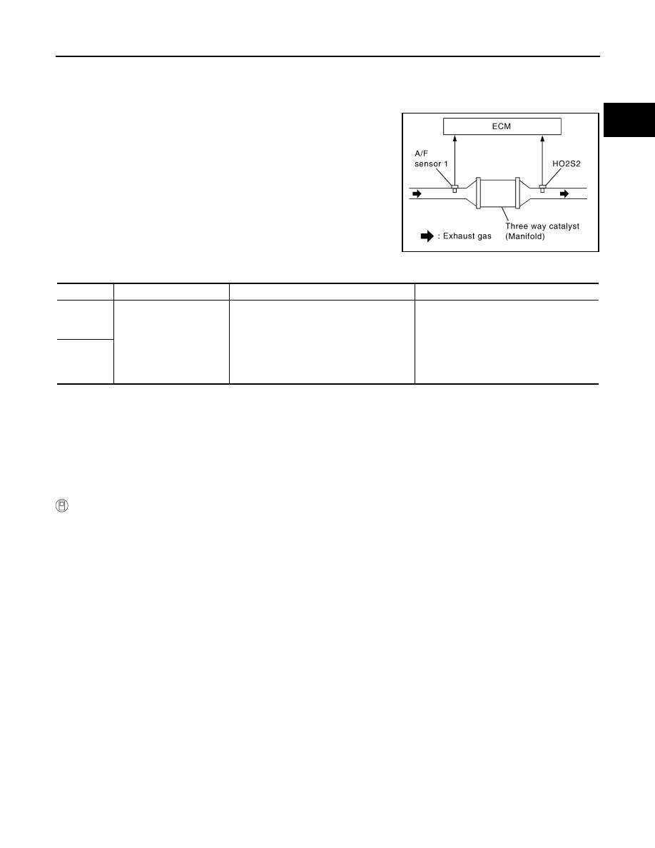
On Board Diagnosis Logic
INFOID:0000000007358620
The ECM monitors the switching frequency ratio of air fuel sensor
(A/F) sensor 1 and heated oxygen sensor 2.
A three way catalyst (manifold) with high oxygen storage capacity
will indicate a low switching frequency of heated oxygen sensor 2.
As oxygen storage capacity decreases, the heated oxygen sensor 2
switching frequency will increase.
When the frequency ratio of air fuel ratio (A/F) sensor 1 and heated
oxygen sensor 2 approaches a specified limit value, the three way
catalyst (manifold) malfunction is diagnosed.
DTC Confirmation Procedure
INFOID:0000000007358621
NOTE:
If DTC Confirmation Procedure has been previously conducted, always perform the following procedure
before conducting the next step.
1. Turn ignition switch OFF and wait at least 10 seconds.
2. Turn ignition switch ON.
3. Turn ignition switch OFF and wait at least 10 seconds.
WITH CONSULT
TESTING CONDITION:
Do not hold engine speed for more than the specified minutes below.
1. Turn ignition switch ON and select “DATA MONITOR” mode with CONSULT.
2. Start engine and warm it up to the normal operating temperature.
3. Turn ignition switch OFF and wait at least 10 seconds.
4. Turn ignition switch ON.
5. Turn ignition switch OFF and wait at least 10 seconds.
6. Start engine and keep the engine speed between 3,500 and 4,000 rpm for at least 1 minute under no load.
7. Let engine idle for 1 minute.
8. Check that “COOLAN TEMP/S” indicates more than 70
°
C (158
°
F).
If not, warm up engine and go to next step when “COOLAN TEMP/S” indication reaches 70
°
C (158
°
F).
9. Open engine hood.
10. Select “DTC & SRT CONFIRMATION” then “SRT WORK SUPPORT” mode with CONSULT.
11. Rev engine between 2,000 and 3,000 rpm and hold it for 3 consecutive minutes, then release the acceler-
ator pedal completely.
If “INCMP” of “CATALYST” changed to “CMPLT”, go to step 14.
12. Wait 5 seconds at idle.
13. Rev engine between 2,000 and 3,000 rpm and maintain it until “INCMP” of “CATALYST” changes to
“CMPLT” (It will take approximately 5 minutes).
If not “CMPLT”, stop engine and cool it down to less than 70
°
C (158
°
F), and then retest from step 1.
14. Select “SELF-DIAG RESULTS” mode with CONSULT.
PBIB2055E
DTC No.
Trouble diagnosis name
DTC detecting condition
Possible cause
P0420
0420
(Bank 1)
Catalyst system efficiency
below threshold
• Three way catalyst (manifold) does not
operate properly.
• Three way catalyst (manifold) does not
have enough oxygen storage capacity.
• Three way catalyst (manifold)
• Exhaust tube
• Intake air leakage
• Fuel injector
• Fuel injector leakage
• Spark plug
• Improper ignition timing
P0430
0430
(Bank 2)
August 2012
2012 Pathfinder
EC-754
< DTC/CIRCUIT DIAGNOSIS >
[VK56DE]
P0420, P0430 THREE WAY CATALYST FUNCTION
15. Check 1st trip DTC.
If the 1st trip DTC is detected, go to
.
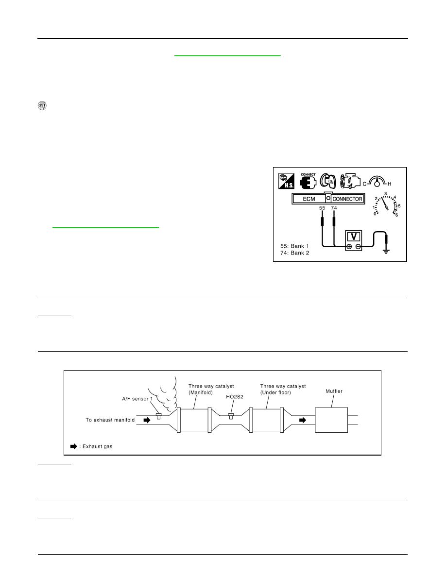
Overall Function Check
INFOID:0000000007358622
Use this procedure to check the overall function of the three way catalyst (manifold). During this check, a 1st
trip DTC might not be confirmed.
WITH GST
1. Start engine and warm it up to the normal operating temperature.
2. Turn ignition switch OFF and wait at least 10 seconds.
3. Start engine and keep the engine speed between 3,500 and 4,000 rpm for at least 1 minute under no load.
4. Let engine idle for 1 minute.
5. Open engine hood.
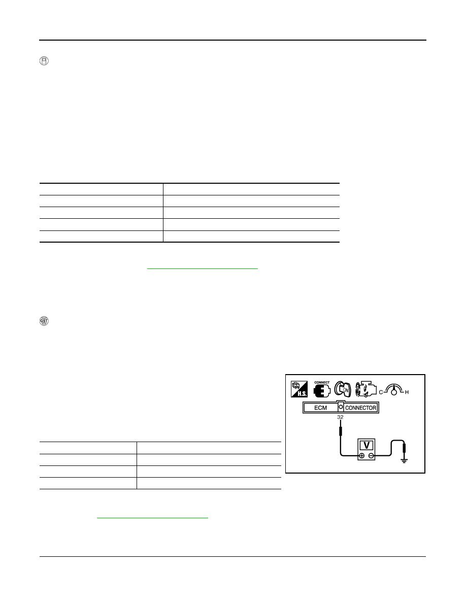
6. Set voltmeter probes between ECM terminal 55 [HO2S2 (bank
1) signal] and ground, ECM terminal 74 [HO2S2 (bank 2) signal]
and ground.
7. Keep engine speed at 2,500 rpm constant under no load.
8. Check that the voltage does not vary for more than 5 seconds.
If the voltage fluctuation cycle takes less than 5 seconds, go to
• 1 cycle: 0.6 - 1.0
→
0 - 0.3
→
0.6 - 1.0
Diagnosis Procedure
INFOID:0000000007358623
1.
CHECK EXHAUST SYSTEM
Visually check exhaust tubes and muffler for dents.
OK or NG
OK
>> GO TO 2.
NG
>> Repair or replace malfunctioning part.
2.
CHECK EXHAUST GAS LEAKAGE
1. Start engine and run it at idle.
2. Listen for an exhaust gas leakage before the three way catalyst (manifold).
OK or NG
OK
>> GO TO 3.
NG
>> Repair or replace malfunctioning part.
3.
CHECK INTAKE AIR LEAKAGE
Listen for an intake air leakage after the mass air flow sensor.
OK or NG
OK
>> GO TO 4.
NG
>> Repair or replace malfunctioning part.
4.
CHECK IGNITION TIMING
PBIB2056E
PBIB1216E
August 2012
2012 Pathfinder
P0420, P0430 THREE WAY CATALYST FUNCTION
EC-755
< DTC/CIRCUIT DIAGNOSIS >
[VK56DE]
C
D
E
F
G
H
I
J
K
L
M
A
EC
N
P
O
Check the following items. Refer to
OK or NG
OK
>> GO TO 5.
NG
>> Follow the instructions on
.
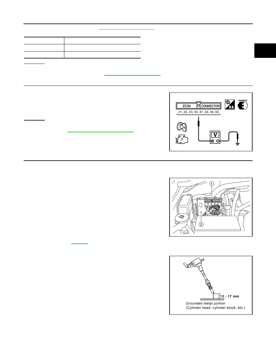
5.
CHECK FUEL INJECTOR
1. Stop engine and then turn ignition switch ON.
2. Check voltage between ECM terminals 21, 22, 23, 40, 41, 42,
44, 63 and ground with CONSULT or tester.
OK or NG
OK
>> GO TO 6.
NG
>> Perform
.
6.
CHECK FUNCTION OF IGNITION COIL-I
CAUTION:
Never following procedure in a place with no combustible objects and good ventilation.
1. Turn ignition switch OFF.
2. Remove fuel pump fuse (1) in IPDM E/R (2) to release fuel pres-
sure.
NOTE:
Do not use CONSULT to release fuel pressure, or fuel pressure
applies again during the following procedure.
3. Start engine.
4. After engine stalls, crank it 2 or 3 times to release all fuel pres-
sure.
5. Turn ignition switch OFF.
6. Remove all ignition coil harness connectors to avoid the electri-
cal discharge from the ignition coils.
7. Remove ignition coil and spark plug of the cylinder to be
.
8. Crank engine for 5 seconds or more to remove combustion gas in the cylinder.
9. Connect spark plug and harness connector to ignition coil.
10. Fix ignition coil using a rope etc. with gap of 13 - 17 mm
between the edge of the spark plug and grounded metal portion
as shown in the figure.
11. Crank engine for approximately 3 seconds, and check whether
spark is generated between the spark plug and the grounded
metal portion.
CAUTION:
• Never place the spark plug and the ignition coil within 50
cm each other. Be careful not to get an electrical shock
while checking, because the electrical discharge voltage
becomes 20 kV or more.
• It might damage the ignition coil if the gap of more than 17 mm is made.
NOTE:
When the gap is less than 13 mm, a spark might be generated even if the coil is malfunctioning.
Items
Specifications
Idle speed
650
±
50 rpm (in P or N position)
Ignition timing
15
±
5
°
BTDC (in P or N position)
Battery voltage should exist.
PBIB1527E
Spark should be generated.
ALBIA0351ZZ
PBIB2325E
August 2012
2012 Pathfinder
EC-756
< DTC/CIRCUIT DIAGNOSIS >
[VK56DE]
P0420, P0430 THREE WAY CATALYST FUNCTION
OK or NG
OK
>> GO TO 10.
NG
>> GO TO 7.
7.
CHECK FUNCTION OF IGNITION COIL-II
1. Turn ignition switch OFF.
2. Disconnect spark plug and connect a non-malfunctioning spark plug.
3. Crank engine for approximately 3 seconds, and recheck whether spark is generated between the spark
plug and the grounded metal portion.
OK or NG
OK
>> GO TO 8.
NG
>> Check ignition coil, power transistor and their circuits. Refer to
.
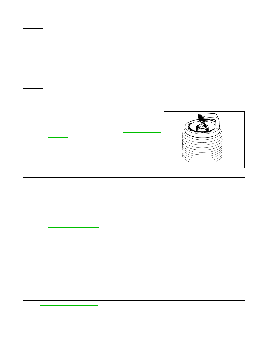
8.
CHECK SPARK PLUG
Check the initial spark plug for fouling, etc.
OK or NG
OK
>> Replace malfunctioning spark plug(s) with standard type
one(s). For spark plug type, refer to
NG
>> 1. Repair or clean spark plug. Refer to
2. GO TO 9.
9.
CHECK FUNCTION OF IGNITION COIL-III
1. Reconnect the initial spark plugs.
2. Crank engine for approximately 3 seconds, and recheck whether spark is generated between the spark
plug and the grounded portion.
OK or NG
OK
>>
INSPECTION END
NG
>> Replace malfunctioning spark plug(s) with standard type one(s). For spark plug type, refer to
.
10.
CHECK FUEL INJECTOR
1. Turn ignition switch OFF.
2. Remove fuel injector assembly. Refer to
EM-180, "Removal and Installation"
.
Keep fuel hose and all fuel injectors connected to fuel injector gallery.
3. Disconnect all ignition coil harness connectors.
4. Reconnect all fuel injector harness connector disconnected.
5. Turn ignition switch ON.
Make sure fuel does not drip from fuel injector.
OK or NG
OK (Does not drip.)>>GO TO 11.
NG (Drips.)>>Replace the fuel injector(s) from which fuel is dripping. Refer to
11.
CHECK INTERMITTENT INCIDENT
GI-37, "Intermittent Incident"
Trouble is fixed.>>
INSPECTION END
Trouble is not fixed.>>Replace malfunctioning three way catalyst assembly. Refer to
Spark should be generated.
SEF156I
Spark should be generated.
August 2012
2012 Pathfinder

P0441 EVAP CONTROL SYSTEM
EC-757
< DTC/CIRCUIT DIAGNOSIS >
[VK56DE]
C
D
E
F
G
H
I
J
K
L
M
A
EC
N
P
O
P0441 EVAP CONTROL SYSTEM
System Description
INFOID:0000000007358624
NOTE:
If DTC P0441 is displayed with other DTC such as P2122, P2123, P2127, P2128 or P2138, first perform
the trouble diagnosis for other DTC.
In this evaporative emission (EVAP) control system, purge flow occurs during non-closed throttle conditions.
Purge volume is related to air intake volume. Under normal purge conditions (non-closed throttle), the EVAP
canister purge volume control solenoid valve is open to admit purge flow. Purge flow exposes the EVAP con-
trol system pressure sensor to intake manifold vacuum.
On Board Diagnosis Logic
INFOID:0000000007358625
Under normal conditions (non-closed throttle), sensor output voltage indicates if pressure drop and purge flow
are adequate. If not, a malfunction is determined.
DTC Confirmation Procedure
INFOID:0000000007358626
CAUTION:
Always drive vehicle at a safe speed.
NOTE:
If DTC Confirmation Procedure has been previously conducted, always perform the following procedure
before conducting the next step.
1. Turn ignition switch OFF and wait at least 10 seconds.
2. Turn ignition switch ON.
3. Turn ignition switch OFF and wait at least 10 seconds.
TESTING CONDITION:
PBIB3640E
DTC No. Trouble diagnosis name
DTC detecting condition
Possible cause
P0441
0441
EVAP control system in-
correct purge flow
EVAP control system does not operate properly.
EVAP control system has a leak between intake
manifold and EVAP control system pressure
sensor.
• EVAP canister purge volume control sole-
noid valve stuck closed
• EVAP control system pressure sensor and
the circuit
• Loose, disconnected or improper connec-
tion of rubber tube
• Blocked rubber tube
• Cracked EVAP canister
• EVAP canister purge volume control sole-
noid valve circuit
• Accelerator pedal position sensor
• Blocked purge port
• EVAP canister vent control valve
• Drain filter
August 2012
2012 Pathfinder
EC-758
< DTC/CIRCUIT DIAGNOSIS >
[VK56DE]
P0441 EVAP CONTROL SYSTEM
Always perform test at a temperature of 5
°
C (41
°
F) or more.
WITH CONSULT
1. Start engine and warm it up to normal operating temperature.
2. Turn ignition switch OFF and wait at least 10 seconds.
3. Turn ignition switch ON.
4. Turn ignition switch OFF and wait at least 10 seconds.
5. Start engine and let it idle for at least 70 seconds.
6. Select “PURG FLOW P0441” of “EVAPORATIVE SYSTEM” in “DTC WORK SUPPORT” mode with CON-
SULT.
7. Touch “START”.
If “COMPLETED” is displayed, go to step 9.
8. When the following conditions are met, “TESTING” will be displayed on the CONSULT screen.
Maintain the conditions continuously until “TESTING” changes to “COMPLETED”. (It will take at least 35
seconds.)
If “TESTING” does not change for a long time, retry from step 2.
9. Check that “OK” is displayed after touching “SELF-DIAG RESULTS”.
If “NG” is displayed, go to
.
Overall Function Check
INFOID:0000000007358627
Use this procedure to check the overall function of the EVAP control system purge flow monitoring. During this
check, a 1st trip DTC might not be confirmed.
WITH GST
1. Lift up drive wheels.
2. Start engine (VDC switch OFF) and warm it up to normal operating temperature.
3. Turn ignition switch OFF, wait at least 10 seconds.
4. Start engine and wait at least 70 seconds.
5. Set voltmeter probes to ECM terminals 32 (EVAP control system
pressure sensor signal) and ground.
6. Check EVAP control system pressure sensor value at idle speed
and note it.
7. Establish and maintain the following conditions for at least 1
minute.
8. Verify that EVAP control system pressure sensor value stays 0.1 V less than the value at idle speed (mea-
sured at step 8) for at least 1 second.
9. If NG, go to
Diagnosis Procedure
INFOID:0000000007358628
1.
CHECK EVAP CANISTER
1. Turn ignition switch OFF.
2. Check EVAP canister for cracks.
Selector lever
Suitable position
VHCL SPEED SE
32 - 120 km/h (20 - 75 MPH)
ENG SPEED
500 - 3,000 rpm
B/FUEL SCHDL
1.0 - 12.0 msec
COOLAN TEMP/S
More than 0
°
C (32
°
F)
Air conditioner switch
ON
Headlamp switch
ON
Engine speed
Approx. 3,000 rpm
Selector lever position
Any position other than P, N or R
PBIB1109E
August 2012
2012 Pathfinder

P0441 EVAP CONTROL SYSTEM
EC-759
< DTC/CIRCUIT DIAGNOSIS >
[VK56DE]
C
D
E
F
G
H
I
J
K
L
M
A
EC
N
P
O
OK or NG
OK (With CONSULT)>>GO TO 2.
OK (Without CONSULT)>>GO TO 3.
NG
>> Replace EVAP canister. Refer to
FL-16, "Removal and Installation"
2.
CHECK PURGE FLOW
With CONSULT
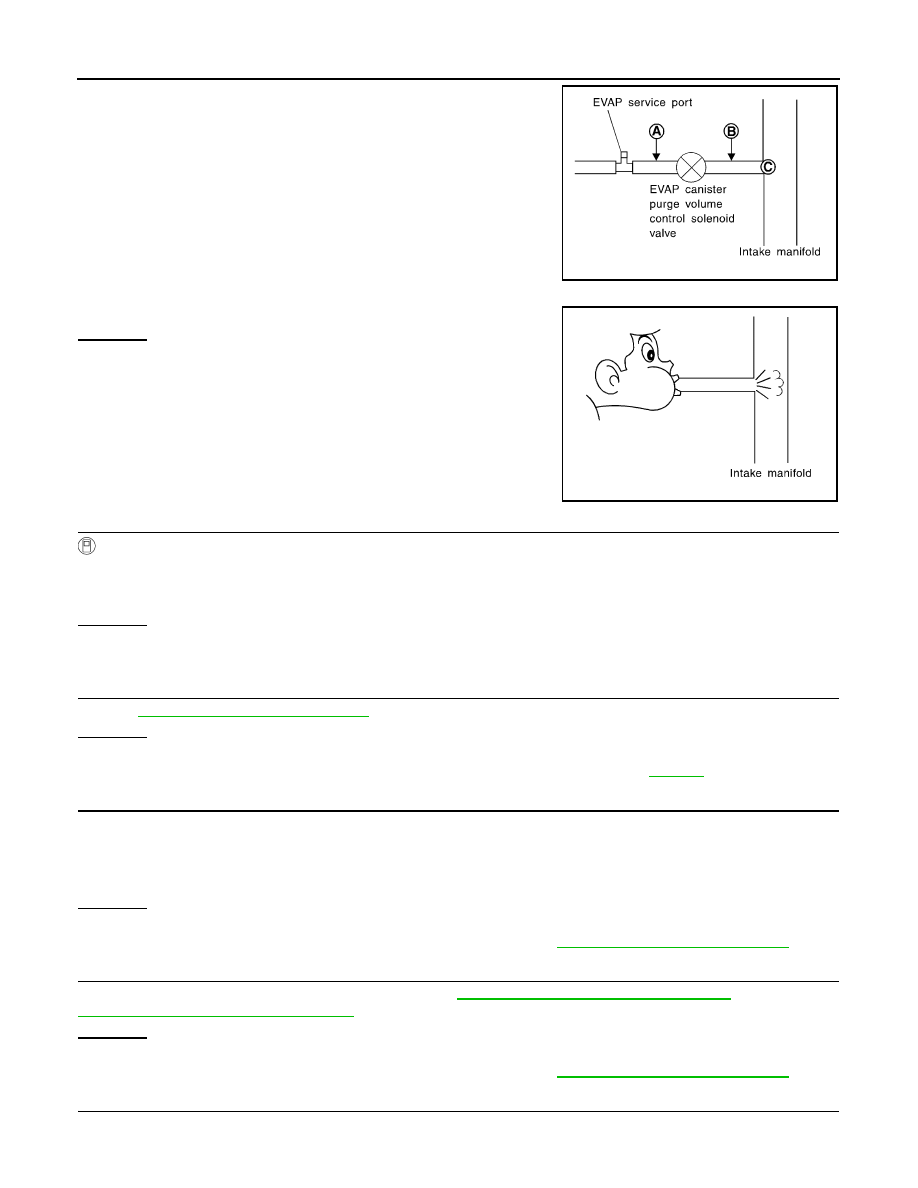
1. Disconnect vacuum hose connected to EVAP canister purge volume control solenoid valve and EVAP
service port from EVAP service port. For the location of EVAP service port, refer to
.
2. Install vacuum gauge between the vacuum hose and EVAP service port.
3. Start engine and let it idle.
4. Select “PURG VOL CONT/V” in “ACTIVE TEST” mode with CONSULT.
5. Rev engine up to 2,000 rpm.
6. Touch “Qd” and “Qu” on CONSULT screen to adjust “PURG VOL C/V” opening and check vacuum exist-
ence.
OK or NG
OK
>> GO TO 7.
NG
>> GO TO 4.
3.
CHECK PURGE FLOW
Without CONSULT
1. Start engine and warm it up to normal operating temperature.
2. Stop engine.
3. Disconnect vacuum hose connected to EVAP canister purge volume control solenoid valve and EVAP
service port from EVAP service port. For the location of EVAP service port, refer to
.
4. Install vacuum gauge between the vacuum hose and EVAP service port.
5. Start engine and let it idle.
Never depress accelerator pedal even slightly.
6. Check vacuum gauge indication before 60 seconds pass after starting engine.
7. Rev engine up to 2,000 rpm after 100 seconds pass after starting engine.
OK or NG
OK
>> GO TO 7.
NG
>> GO TO 4.
4.
CHECK EVAP PURGE LINE
1. Turn ignition switch OFF.
2. Check EVAP purge line for improper connection or disconnection.
OK or NG
OK
>> GO TO 5.
NG
>> Repair malfunctioning part.
5.
CHECK EVAP PURGE HOSE AND PURGE PORT
PURG VOL C/V
Vacuum
100%
Should exist.
0%
Should not exist.
Vacuum should not exist.
Vacuum should exist.
August 2012
2012 Pathfinder
EC-760
< DTC/CIRCUIT DIAGNOSIS >
[VK56DE]
P0441 EVAP CONTROL SYSTEM
1. Disconnect purge hoses connected to EVAP service port
A
and
EVAP canister purge volume control solenoid valve
B
.
2. Blow air into each hose and EVAP purge port
C
.
3. Check that air flows freely.
OK or NG
OK (With CONSULT)>>GO TO 6.
OK (Without CONSULT)>>GO TO 7.
NG
>> Repair or clean hoses and/or purge port.
6.
CHECK EVAP CANISTER PURGE VOLUME CONTROL SOLENOID VALVE
With CONSULT
1. Start engine.
2. Perform “PURG VOL CONT/V” in “ACTIVE TEST” mode with CONSULT. Check that engine speed varies
according to the valve opening.
OK or NG
OK
>> GO TO 8.
NG
>> GO TO 7.
7.
CHECK EVAP CANISTER PURGE VOLUME CONTROL SOLENOID VALVE
EC-776, "Component Inspection"
OK or NG
OK
>> GO TO 8.
NG
>> Replace EVAP canister purge volume control solenoid valve. Refer to
.
8.
CHECK EVAP CONTROL SYSTEM PRESSURE SENSOR CONNECTOR
1. Disconnect EVAP control system pressure sensor harness connector.
2. Check connectors for water.
OK or NG
OK
>> GO TO 9.
NG
>> Replace EVAP control system pressure sensor. Refer to
FL-16, "Removal and Installation"
.
9.
CHECK EVAP CONTROL SYSTEM PRESSURE SENSOR FUNCTION
Refer to DTC Confirmation Procedure for DTC P0452,
EC-790, "DTC Confirmation Procedure"
and for P0453,
EC-794, "DTC Confirmation Procedure"
OK or NG
OK
>> GO TO 10.
NG
>> Replace EVAP control system pressure sensor. Refer to
FL-16, "Removal and Installation"
.
10.
CHECK RUBBER TUBE FOR CLOGGING
1. Disconnect rubber tube connected to EVAP canister vent control valve.
SEF367U
SEF368U
Water should not exist.
August 2012
2012 Pathfinder
Нет комментариевНе стесняйтесь поделиться с нами вашим ценным мнением.
Текст