Nissan Pathfinder (2012 year). Instruction — part 230
FRONT FINAL DRIVE
DLN-405
< UNIT DISASSEMBLY AND ASSEMBLY >
[FRONT FINAL DRIVE: M205]
C
E
F
G
H
I
J
K
L
M
A
B
DLN
N
O
P
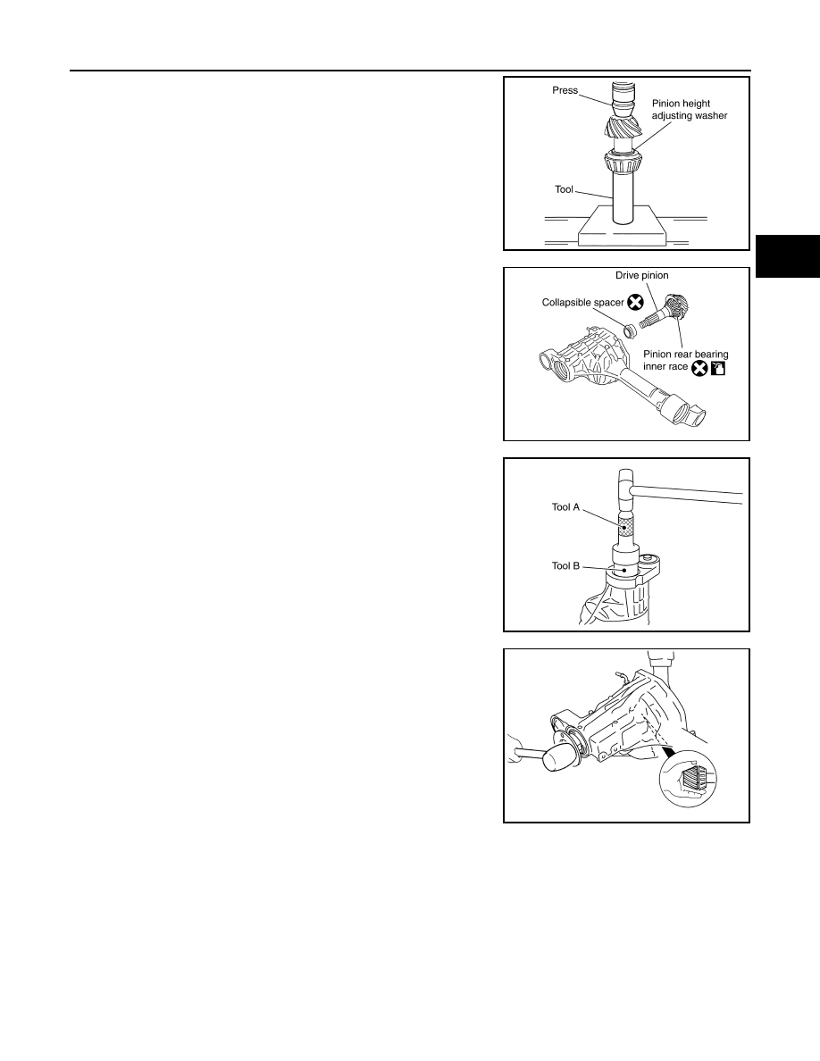
4. Install the selected drive pinion height adjusting washer to the
drive pinion. Press the drive pinion rear bearing inner race to it
using Tool.
CAUTION:
Do not reuse drive pinion rear bearing inner race.
5. Install the collapsible spacer to the drive pinion.
CAUTION:
Do not reuse collapsible spacer.
6. Apply differential gear oil to the drive pinion rear bearing, and
install the drive pinion assembly to the gear carrier.
7. Apply differential gear oil to the drive pinion front bearing, and
install the drive pinion front bearing inner race to the drive pinion
assembly.
CAUTION:
Do not reuse drive pinion front bearing inner race.
8. Apply multi-purpose grease to the lips of the new front oil seal.
Then drive the new front oil seal in evenly using Tools.
CAUTION:
• Do not reuse front oil seal.
• Do not incline the new front oil seal when installing.
• Apply multi-purpose grease to the lips of the new front oil
seal.
9. Install the companion flange to the drive pinion while aligning the
matching marks. Tap the companion flange until fully seated
using suitable tool.
Tool number
: — C-4040
SDIA2253E
PDIA0708E
Tool number
(A): KV38100500 (J-25273)
(B): KV38102200 ( — )
PDIA0717E
SDIA2266E
August 2012
2012 Pathfinder
DLN-406
< UNIT DISASSEMBLY AND ASSEMBLY >
[FRONT FINAL DRIVE: M205]
FRONT FINAL DRIVE
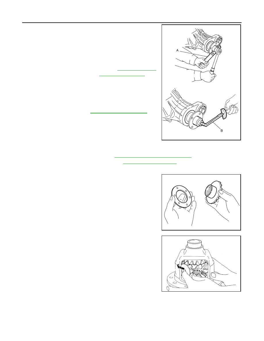
10. Apply anti-corrosive oil to the threads of the drive pinion and the
seating surface of the new drive pinion lock nut. Then adjust the
drive pinion lock nut tightening torque using suitable tool (A),
and check the drive pinion bearing preload torque using Tool
(B).
CAUTION:
• Do not reuse drive pinion lock nut.
• Apply anti-corrosive oil to the threads of the drive pinion
and the seating surface of the new drive pinion lock nut.
• Adjust the drive pinion lock nut tightening torque to the
lower limit first. Do not exceed the drive pinion lock nut
specified torque. Refer to
.
• If the drive pinion bearing preload torque exceeds the
specified value, replace collapsible spacer and tighten it
again to adjust. Do not loosen drive pinion lock nut to
adjust the drive pinion bearing preload torque.
• After adjustment, rotate drive pinion back and forth 2 to 3
times to check for unusual noise, rotation malfunction,
and other malfunctions.
11. Check companion flange runout. Refer to
DLN-410, "Inspection and Adjustment"
.
12. Install the differential case assembly. Refer to
Differential Assembly
1. Install side gear thrust washers with the same thickness as the
ones installed prior to disassembly, or reinstall the old ones on
the side gears.
2. Install the side gears and side gear thrust washers into the dif-
ferential case.
3. Install the pinion mate thrust washers to the two pinion mate
gears. Then install the pinion mate gears with the pinion mate
thrust washers by aligning them in diagonally opposite positions
and rotating them into the differential case.
Tool number
(B): ST3127S000 (J-25765-A)
Drive pinion bearing pre-
load torque
WDIA0382E
SDIA0193J
SDIA2025E
August 2012
2012 Pathfinder
FRONT FINAL DRIVE
DLN-407
< UNIT DISASSEMBLY AND ASSEMBLY >
[FRONT FINAL DRIVE: M205]
C
E
F
G
H
I
J
K
L
M
A
B
DLN
N
O
P
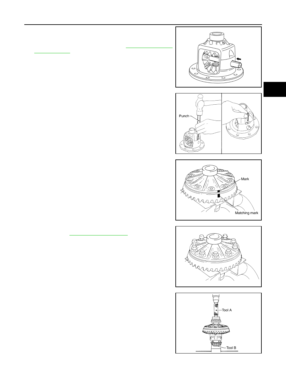
4. Install the pinion mate shaft and align the lock pin hole on the
pinion mate shaft with the lock pin hole on the differential case.
5. Measure the side gear end play. If necessary, select the appro-
priate side gear thrust washers. Refer to
6. Drive a new lock pin into the pinion mate shaft until it is flush
with the differential case using suitable tool.
CAUTION:
Do not reuse lock pin.
7. Align the matching mark of the differential case with the mark of
the drive gear, then place the drive gear onto the differential
case.
8. Install and tighten the new drive gear bolts to the specified
CAUTION:
• Make sure the drive gear back and threaded holes are
clean.
• Do not reuse drive gear bolts.
• Tighten new drive gear bolts in a crisscross pattern.
9. Press the new side bearing inner races to the differential case
using Tools.
CAUTION:
Do not reuse side bearing inner races.
SDIA0195J
SPD030
SDIA2593E
SDIA2239E
Tool number
(A): KV38100300 (J-25523)
(B): ST33081000 ( — )
SPD353
August 2012
2012 Pathfinder
DLN-408
< UNIT DISASSEMBLY AND ASSEMBLY >
[FRONT FINAL DRIVE: M205]
FRONT FINAL DRIVE
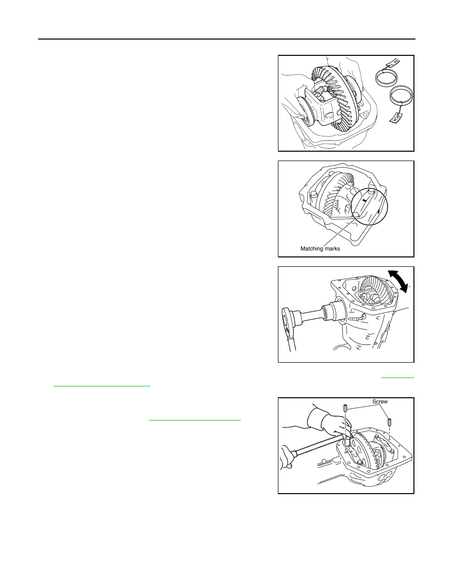
10. Install side bearing adjusters into gear carrier.
11. Apply differential gear oil to the side bearings, and install the dif-
ferential case assembly with the side bearing outer races into
the gear carrier.
CAUTION:
Do not reuse side bearing outer race when replacing side
bearing inner race (replace as a set).
12. Install the side bearing caps with the matching marks aligned.
NOTE:
Do not tighten at this step. This allows further tightening of side
bearing adjusters.
13. Tighten each side bearing adjuster alternately turning drive gear.
14. Check and adjust tooth contact, backlash, drive gear runout and total preload torque. Refer to
.
Recheck above items.
• After adjusting tooth contact and backlash secure side bearing
adjuster with screws and tighten side bearing cap bolt to the
specified torque. Refer to
15. Apply multi-purpose grease to the lips of the new side oil seal. Then drive the new side oil seal in evenly to
the gear carrier using suitable tool.
CAUTION:
• Do not reuse side oil seal.
• Do not incline the new side oil seal when installing.
• Apply multi-purpose grease to the lips of the new side oil seal.
SPD527
PDIA0700E
SDIA2265E
SDIA2263E
August 2012
2012 Pathfinder
FRONT FINAL DRIVE
DLN-409
< UNIT DISASSEMBLY AND ASSEMBLY >
[FRONT FINAL DRIVE: M205]
C
E
F
G
H
I
J
K
L
M
A
B
DLN
N
O
P
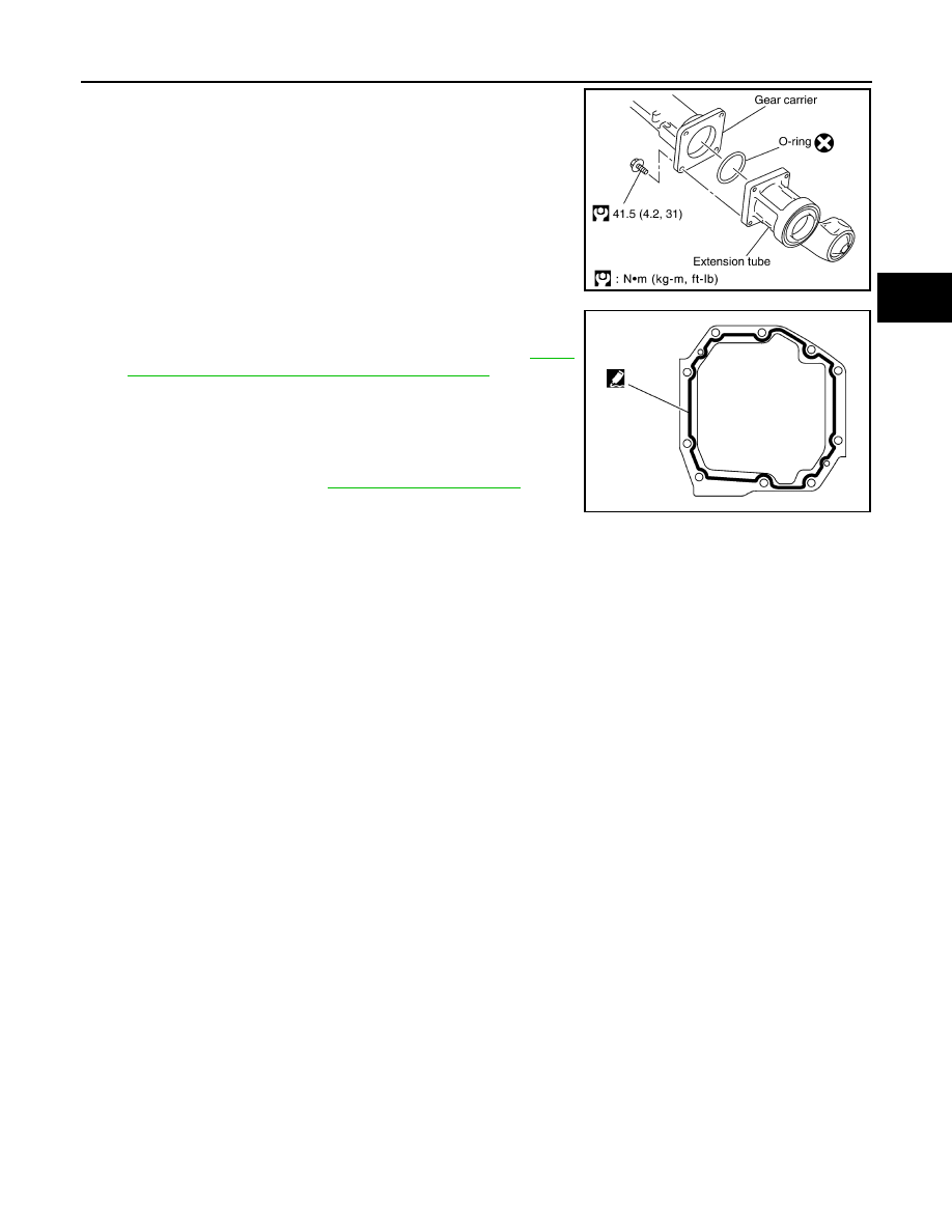
16. Install the extension tube with a new O-ring.
CAUTION:
• Do not reuse O-ring.
• If the extension tube is being replaced, install a new differ-
ential side shaft bearing.
17. Apply 3 mm (0.12 in) bead of sealant to the mating surface of
the carrier cover as shown.
• Use Genuine Silicone RTV or equivalent. Refer to
"Recommended Chemical Products and Sealants"
CAUTION:
Remove any old sealant adhering to the mating surfaces.
Also remove any moisture, oil, or foreign material adhering
to the application and mating surfaces.
18. Install the carrier cover to the gear carrier. Tighten the bolts to
the specified torque. Refer to
.
19. Install differential side shaft and differential side flange.
SDIA3205E
SDIA3204E
August 2012
2012 Pathfinder

DLN-410
< SERVICE DATA AND SPECIFICATIONS (SDS)
[FRONT FINAL DRIVE: M205]
SERVICE DATA AND SPECIFICATIONS (SDS)
SERVICE DATA AND SPECIFICATIONS (SDS)
SERVICE DATA AND SPECIFICATIONS (SDS)
General Specification
INFOID:0000000007357635
Inspection and Adjustment
INFOID:0000000007357636
DRIVE GEAR RUNOUT
Unit: mm (in)
SIDE GEAR CLEARANCE
Unit: mm (in)
PRELOAD TORQUE
Unit: N·m (kg-m, in-lb)
BACKLASH
Unit: mm (in)
COMPANION FLANGE RUNOUT
Unit: mm (in)
SELECTIVE PARTS
Drive Pinion Height Adjusting Washer
Applied model
VK56DE
Final drive model
M205
Gear ratio
2.937
Number of teeth (Drive gear/Drive pinion)
47/16
Differential gear oil capacity (Approx.)
1.6 (3 3/8 US pt, 2 7/8 Imp pt)
Number of pinion gears
2
Drive pinion adjustment spacer type
Collapsible
Item
Runout limit
Drive gear back face
0.08 (0.0031) or less
Item
Specification
Side gear back clearance (Clearance between side gear and dif-
ferential case for adjusting side gear backlash)
0.20 (0.0079) or less
(Each gear should rotate smoothly without excessive resistance
during differential motion.)
Item
Specification
Drive pinion bearing preload torque
2.3 - 3.4 (0.23 - 0.35, 21 - 31)
Total preload torque
(Total preload torque = drive pinion bearing preload torque + side
bearing preload torque).
2.98 - 4.76 (0.31 - 0.48, 27 - 42)
Item
Specification
Drive gear to drive pinion backlash
0.13 - 0.18 (0.0051 - 0.0071)
Item
Runout limit
Companion flange face
0.10 (0.0039) or less
Companion flange inner side
0.13 (0.0051) or less
August 2012
2012 Pathfinder

SERVICE DATA AND SPECIFICATIONS (SDS)
DLN-411
< SERVICE DATA AND SPECIFICATIONS (SDS)
[FRONT FINAL DRIVE: M205]
C
E
F
G
H
I
J
K
L
M
A
B
DLN
N
O
P
Unit: mm (in)
*: Always check with the Parts Department for the latest parts information.
Side Gear Thrust Washer
Unit: mm (in)
*: Always check with the Parts Department for the latest parts information.
Thickness
Package part number*
1.22 (0.048)
1.24 (0.049)
1.27 (0.050)
1.30 (0.051)
1.32 (0.052)
38154 8S111
1.35 (0.053)
1.37 (0.054)
1.40 (0.055)
1.42 (0.056)
1.45 (0.057)
38154 8S112
1.47 (0.058)
1.50 (0.059)
1.52 (0.060)
1.55 (0.061)
1.57 (0.062)
38154 8S113
1.60 (0.063)
1.63 (0.064)
1.65 (0.065)
1.68 (0.066)
1.70 (0.067)
38154 8S114
1.73 (0.068)
1.75 (0.069)
1.78 (0.070)
1.80 (0.071)
1.83 (0.072)
38154 8S115
Thickness
Package part number*
0.76 (0.030)
0.79 (0.031)
0.81 (0.032)
0.84 (0.033)
0.87 (0.034)
38424 8S111
0.89 (0.035)
0.91 (0.036)
0.94 (0.037)
0.97 (0.038)
0.99 (0.039)
38424 8S112
August 2012
2012 Pathfinder
DLN-412
< PRECAUTION >
[REAR FINAL DRIVE: R200]
PRECAUTIONS
PRECAUTION
PRECAUTIONS
Precaution for Supplemental Restraint System (SRS) "AIR BAG" and "SEAT BELT
PRE-TENSIONER"
INFOID:0000000007357637
The Supplemental Restraint System such as “AIR BAG” and “SEAT BELT PRE-TENSIONER”, used along
with a front seat belt, helps to reduce the risk or severity of injury to the driver and front passenger for certain
types of collision. This system includes seat belt switch inputs and dual stage front air bag modules. The SRS
system uses the seat belt switches to determine the front air bag deployment, and may only deploy one front
air bag, depending on the severity of a collision and whether the front occupants are belted or unbelted.
Information necessary to service the system safely is included in the SR and SB section of this Service Man-
ual.
WARNING:
• To avoid rendering the SRS inoperative, which could increase the risk of personal injury or death in
the event of a collision which would result in air bag inflation, all maintenance must be performed by
an authorized NISSAN/INFINITI dealer.
• Improper maintenance, including incorrect removal and installation of the SRS, can lead to personal
injury caused by unintentional activation of the system. For removal of Spiral Cable and Air Bag
Module, see the SR section.
• Do not use electrical test equipment on any circuit related to the SRS unless instructed to in this
Service Instruction. SRS wiring harnesses can be identified by yellow and/or orange harnesses or har-
ness connectors.
PRECAUTIONS WHEN USING POWER TOOLS (AIR OR ELECTRIC) AND HAMMERS
WARNING:
• When working near the Airbag Diagnosis Sensor Unit or other Airbag System sensors with the Igni-
tion ON or engine running, DO NOT use air or electric power tools or strike near the sensor(s) with a
hammer. Heavy vibration could activate the sensor(s) and deploy the air bag(s), possibly causing
serious injury.
• When using air or electric power tools or hammers, always switch the Ignition OFF, disconnect the
battery, and wait at least 3 minutes before performing any service.
Precaution Necessary for Steering Wheel Rotation After Battery Disconnect
INFOID:0000000007357638
NOTE:
• This Procedure is applied only to models with Intelligent Key system and NATS (NISSAN ANTI-THEFT SYS-
TEM).
• Remove and install all control units after disconnecting both battery cables with the ignition knob in the
″
LOCK
″
position.
• Always use CONSULT to perform self-diagnosis as a part of each function inspection after finishing work. If
DTC is detected, perform trouble diagnosis according to self-diagnostic results.
For models equipped with the Intelligent Key system and NATS, an electrically controlled steering lock mech-
anism is adopted on the key cylinder.
For this reason, if the battery is disconnected or if the battery is discharged, the steering wheel will lock and
steering wheel rotation will become impossible.
If steering wheel rotation is required when battery power is interrupted, follow the procedure below before
starting the repair operation.
OPERATION PROCEDURE
1. Connect both battery cables.
NOTE:
Supply power using jumper cables if battery is discharged.
2. Use the Intelligent Key or mechanical key to turn the ignition switch to the
″
ACC
″
position. At this time, the
steering lock will be released.
3. Disconnect both battery cables. The steering lock will remain released and the steering wheel can be
rotated.
4. Perform the necessary repair operation.
August 2012
2012 Pathfinder
Нет комментариевНе стесняйтесь поделиться с нами вашим ценным мнением.
Текст