Nissan Pathfinder (2012 year). Instruction — part 102

BRC-82
< ECU DIAGNOSIS INFORMATION >
[TYPE 1]
ABS ACTUATOR AND ELECTRIC UNIT (CONTROL UNIT)
ABS ACTUATOR AND ELECTRIC UNIT (CONTROL UNIT)
Reference Value
INFOID:0000000007356790
VALUES ON THE DIAGNOSIS TOOL
CAUTION:
The display shows the control unit calculation data, so a normal value might be displayed even in the
event the output circuit (harness) is open or short-circuited.
CONSULT MONITOR ITEM
Monitor item
Display content
Data monitor
Condition
Reference value in
normal operation
FR LH SENSOR
Wheel speed
0 [km/h (MPH)]
Vehicle stopped
Nearly matches the speed meter display
(
±
10% or less)
Vehicle running
(Note 1)
FR RH SENSOR
Wheel speed
0 [km/h (MPH)]
Vehicle stopped
Nearly matches the speed meter display
(
±
10% or less)
Vehicle running
(Note 1)
RR LH SENSOR
Wheel speed
0 [km/h (MPH)]
Vehicle stopped
Nearly matches the speed meter display
(
±
10% or less)
Vehicle running
(Note 1)
RR RH SENSOR
Wheel speed
0 [km/h (MPH)]
Vehicle stopped
Nearly matches the speed meter display
(
±
10% or less)
Vehicle running
(Note 1)
DECEL G-SEN
Longitudinal acceleration detected by Decel
G-Sensor
Vehicle stopped
Approx. 0 G
Vehicle running
-1.7 to 1.7 G
FR RH IN SOL
Operation status of each solenoid valve
Actuator (solenoid valve) is active (“AC-
TIVE TEST” with CONSULT) or actuator
relay is inactive (in fail-safe mode)
ON
When the actuator (solenoid valve) is not
active and actuator relay is active (igni-
tion switch ON)
OFF
FR RH OUT SOL
Operation status of each solenoid valve
Actuator (solenoid valve) is active (“AC-
TIVE TEST” with CONSULT) or actuator
relay is inactive (in fail-safe mode)
ON
When the actuator (solenoid valve) is not
active and actuator relay is active (igni-
tion switch ON)
OFF
FR LH IN SOL
Operation status of each solenoid valve
Actuator (solenoid valve) is active (“AC-
TIVE TEST” with CONSULT) or actuator
relay is inactive (in fail-safe mode)
ON
When the actuator (solenoid valve) is not
active and actuator relay is active (igni-
tion switch ON)
OFF
FR LH OUT SOL
Operation status of each solenoid valve
Actuator (solenoid valve) is active (“AC-
TIVE TEST” with CONSULT) or actuator
relay is inactive (in fail-safe mode)
ON
When the actuator (solenoid valve) is not
active and actuator relay is active (igni-
tion switch ON)
OFF
August 2012
2012 Pathfinder

ABS ACTUATOR AND ELECTRIC UNIT (CONTROL UNIT)
BRC-83
< ECU DIAGNOSIS INFORMATION >
[TYPE 1]
C
D
E
G
H
I
J
K
L
M
A
B
BRC
N
O
P
RR RH IN SOL
Operation status of each solenoid valve
Actuator (solenoid valve) is active (“AC-
TIVE TEST” with CONSULT) or actuator
relay is inactive (in fail-safe mode)
ON
When the actuator (solenoid valve) is not
active and actuator relay is active (igni-
tion switch ON)
OFF
RR RH OUT SOL
Operation status of each solenoid valve
Actuator (solenoid valve) is active (“AC-
TIVE TEST” with CONSULT) or actuator
relay is inactive (in fail-safe mode)
ON
When the actuator (solenoid valve) is not
active and actuator relay is active (igni-
tion switch ON)
OFF
RR LH IN SOL
Operation status of each solenoid valve
Actuator (solenoid valve) is active (“AC-
TIVE TEST” with CONSULT) or actuator
relay is inactive (in fail-safe mode)
ON
When the actuator (solenoid valve) is not
active and actuator relay is active (igni-
tion switch ON)
OFF
RR LH OUT SOL
Operation status of each solenoid valve
Actuator (solenoid valve) is active (“AC-
TIVE TEST” with CONSULT) or actuator
relay is inactive (in fail-safe mode)
ON
When the actuator (solenoid valve) is not
active and actuator relay is active (igni-
tion switch ON)
OFF
EBD WARN LAMP
EBD warning lamp
(Note 2)
When EBD warning lamp is ON
ON
When EBD warning lamp is OFF
OFF
STOP LAMP SW
Stop lamp switch signal status
When brake pedal is depressed
ON
When brake pedal is released
OFF
MOTOR RELAY
Motor and motor relay operation
When the motor relay and motor are op-
erating
ON
When the motor relay and motor are not
operating
OFF
ACTUATOR RLY
Actuator relay operation
When the actuator relay is operating
ON
When the actuator relay is not operating
OFF
ABS WARN LAMP
ABS warning lamp
(Note 2)
When ABS warning lamp is ON
ON
When ABS warning lamp is OFF
OFF
OFF LAMP
VDC OFF indicator lamp
(Note 2)
When VDC OFF indicator lamp is ON
ON
When VDC OFF indicator lamp is OFF
OFF
OFF SW
VDC OFF switch ON/OFF
VDC OFF switch ON
(When VDC OFF indicator lamp is ON)
ON
VDC OFF switch OFF
(When VDC OFF indicator lamp is OFF)
OFF
SLIP LAMP
SLIP indicator lamp
(Note 2)
When SLIP indicator lamp is ON
ON
When SLIP indicator lamp is OFF
OFF
BATTERY VOLT
Battery voltage supplied to the ABS actuator
and electric unit (control unit)
Ignition switch ON
10 – 16 V
GEAR
Gear position determined by TCM
1st gear
2nd gear
3rd gear
4th gear
5th gear
1
2
3
4
5
Monitor item
Display content
Data monitor
Condition
Reference value in
normal operation
August 2012
2012 Pathfinder

BRC-84
< ECU DIAGNOSIS INFORMATION >
[TYPE 1]
ABS ACTUATOR AND ELECTRIC UNIT (CONTROL UNIT)
SLCT LVR POSI
A/T selector lever position
P position
R position
N position
D position
P
R
N
D
ENGINE SPEED
With engine running
With engine stopped
0 rpm
Engine running
Almost in accor-
dance with tachome-
ter display
YAW RATE SEN
Yaw rate detected by yaw rate/side/decel G
sensor
When vehicle is stopped
Approx. 0 d/s
When vehicle turning
−
75 to 75 d/s
R POSI SIG
Transmission range switch signal ON/OFF
condition
A/T shift position = R position
ON
A/T shift position = other than R position
OFF
4WD FAIL REQ
(Note 3)
Transfer control unit fail-safe signal
When transfer control unit is in fail-safe
mode
ON
When transfer control unit is normal
OFF
N POSI SIG
Transmission range switch signal ON/OFF
condition
A/T shift position = N position
ON
A/T shift position = other than N position
OFF
P POSI SIG
Transmission range switch signal ON/OFF
condition
A/T shift position = P position
ON
A/T shift position = other than P position
OFF
CV1
VDC switch-over valve
When actuator (switch-over valve) is ac-
tive (“ACTIVE TEST” with CONSULT) or
actuator relay is inactive (when in fail-
safe mode)
ON
When actuator (switch-over valve) is not
active and actuator relay is active (igni-
tion switch ON)
OFF
CV2
VDC switch-over valve
When actuator (switch-over valve) is ac-
tive (“ACTIVE TEST” with CONSULT) or
actuator relay is inactive (when in fail-
safe mode)
ON
When actuator (switch-over valve) is not
active and actuator relay is active (igni-
tion switch ON)
OFF
SV1
VDC switch-over valve
When actuator (switch-over valve) is ac-
tive (“ACTIVE TEST” with CONSULT) or
actuator relay is inactive (when in fail-
safe mode)
ON
When actuator (switch-over valve) is not
active and actuator relay is active (igni-
tion switch ON)
OFF
SV2
VDC switch-over valve
When actuator (switch-over valve) is ac-
tive (“ACTIVE TEST” with CONSULT) or
actuator relay is inactive (when in fail-
safe mode)
ON
When actuator (switch-over valve) is not
active and actuator relay is active (igni-
tion switch ON)
OFF
2WD/4WD
Drive axle
2WD model
2WD
4WD model
4WD
Monitor item
Display content
Data monitor
Condition
Reference value in
normal operation
August 2012
2012 Pathfinder

ABS ACTUATOR AND ELECTRIC UNIT (CONTROL UNIT)
BRC-85
< ECU DIAGNOSIS INFORMATION >
[TYPE 1]
C
D
E
G
H
I
J
K
L
M
A
B
BRC
N
O
P
NOTE:
• 1: Confirm tire pressure is normal.
• 2: On and off timing for warning lamp and indicator lamp.
• 3: Only 4WD models.
- ABS warning lamp: Refer to
.
- Brake warning lamp: Refer to
- VDC OFF indicator lamp: Refer to
- SLIP indicator lamp: Refer to
ACCEL POS SIG
Throttle actuator opening/closing is dis-
played (linked with accelerator pedal)
Accelerator pedal not depressed (ignition
switch is ON)
0 %
Accelerator pedal depressed (ignition
switch is ON)
0 - 100 %
SIDE G-SENSOR
Transverse G detected by side G sensor
Vehicle stopped
Approx. 0 m/s
2
Vehicle turning right
Negative value
(m/s
2
)
Vehicle turning left
Positive value
(m/s
2
)
STR ANGLE SIG
Steering angle detected by steering angle
sensor
Straight-ahead
Approx. 0
±
2.5
°
Steering wheel turned
–720 to +720
°
PRESS SENSOR
Brake fluid pressure detected by pressure
sensor
With ignition switch turned ON and brake
pedal released
Approx. 0 bar
With ignition switch turned ON and brake
pedal depressed
–40 to 300 bar
EBD SIGNAL
EBD operation
EBD is active
ON
EBD is inactive
OFF
ABS SIGNAL
ABS operation
ABS is active
ON
ABS is inactive
OFF
TCS SIGNAL
TCS operation
TCS is active
ON
TCS is inactive
OFF
VDC SIGNAL
VDC operation
VDC is active
ON
VDC is inactive
OFF
EBD FAIL SIG
EBD fail-safe signal
In EBD fail-safe
ON
EBD is normal
OFF
ABS FAIL SIG
ABS fail-safe signal
In ABS fail-safe
ON
ABS is normal
OFF
TCS FAIL SIG
TCS fail-safe signal
In TCS fail-safe
ON
TCS is normal
OFF
VDC FAIL SIG
VDC fail-safe signal
In VDC fail-safe
ON
VDC is normal
OFF
CRANKING SIG
Crank operation
Crank is active
ON
Crank is inactive
OFF
FLUID LEV SW
Brake fluid level switch signal status
When brake fluid level switch ON
ON
When brake fluid level switch OFF
OFF
Monitor item
Display content
Data monitor
Condition
Reference value in
normal operation
August 2012
2012 Pathfinder
BRC-86
< ECU DIAGNOSIS INFORMATION >
[TYPE 1]
ABS ACTUATOR AND ELECTRIC UNIT (CONTROL UNIT)
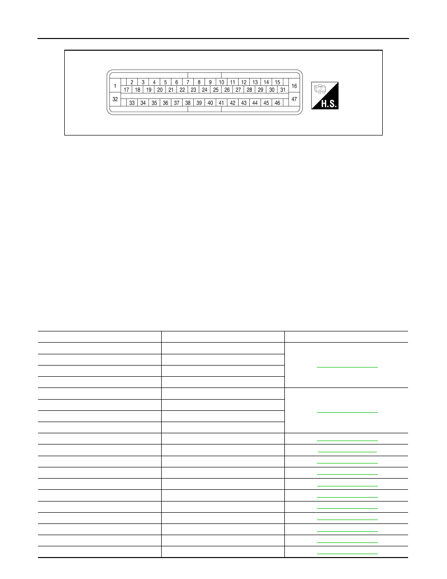
TERMINAL LAYOUT
Fail-Safe
INFOID:0000000007356791
CAUTION:
If the Fail-Safe function is activated, perform Self Diagnosis for VDC/TCS/ABS system.
ABS/EBD SYSTEM
In case of an electrical malfunction with the ABS, the ABS warning lamp and SLIP indicator lamp will turn on.
In case of an electrical malfunction with the EBD system, the BRAKE warning lamp, ABS warning lamp and
SLIP indicator lamp will turn on.
The system will revert to one of the following conditions of the Fail-Safe function.
1. For ABS malfunction, only the EBD is operative and the condition of the vehicle is the same condition of
vehicles without VDC/TCS/ABS system.
2. For EBD malfunction, the EBD and ABS become inoperative, and the condition of the vehicle is the same
as the condition of vehicles without VDC/TCS/ABS or EBD system.
VDC/TCS SYSTEM
In case of VDC/TCS system malfunction, the SLIP indicator lamp is turned on and the condition of the vehicle
is the same as the condition of vehicles without VDC/TCS system. In case of an electrical malfunction with the
VDC/TCS system, the ABS control continues to operate normally without VDC/TCS control.
DTC No. Index
INFOID:0000000007356792
AWFIA0032ZZ
DTC
Items (CONSULT screen terms)
Reference
C1101
RR RH SENSOR-1
C1102
RR LH SENSOR-1
C1103
FR RH SENSOR-1
C1104
FR LH SENSOR-1
C1105
RR RH SENSOR-2
C1106
RR LH SENSOR-2
C1107
FR RH SENSOR-2
C1108
FR LH SENSOR-2
C1109
BATTERY VOLTAGE [ABNORMAL]
C1110
CONTROLLER FAILURE
C1111
PUMP MOTOR
C1113
G-SENSOR
C1115
ABS SENSOR [ABNORMAL SIGNAL]
C1116
STOP LAMP SW
C1120
FR LH IN ABS SOL
C1121
FR LH OUT ABS SOL
C1122
FR RH IN ABS SOL
C1123
FR RH OUT ABS SOL
C1124
RR LH IN ABS SOL
August 2012
2012 Pathfinder

ABS ACTUATOR AND ELECTRIC UNIT (CONTROL UNIT)
BRC-87
< ECU DIAGNOSIS INFORMATION >
[TYPE 1]
C
D
E
G
H
I
J
K
L
M
A
B
BRC
N
O
P
C1125
RR LH OUT ABS SOL
C1126
RR RH IN ABS SOL
C1127
RR RH OUT ABS SOL
C1130
ENGINE SIGNAL 1
C1131
ENGINE SIGNAL 2
C1132
ENGINE SIGNAL 3
C1133
ENGINE SIGNAL 4
C1136
ENGINE SIGNAL 6
C1140
ACTUATOR RLY
C1143
ST ANG SEN CIRCUIT
C1144
ST ANG SEN SIGNAL
C1145
YAW RATE SENSOR
C1146
SIDE G-SEN CIRCUIT
C1155
BR FLUID LEVEL LOW
C1156
ST ANG SEN COM CIR
C1160
DECEL G SEN SET
C1163
ST ANGL SEN SAFE
C1164
CV1
C1165
CV2
C1166
SV1
C1167
SV2
C1170
VARIANT CODING
U1000
CAN COMM CIRCUIT
DTC
Items (CONSULT screen terms)
Reference
August 2012
2012 Pathfinder
BRC-88
< WIRING DIAGRAM >
[TYPE 1]
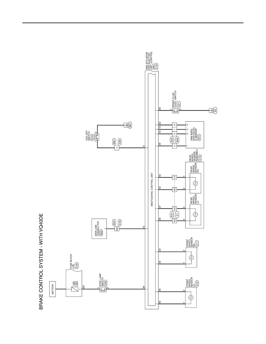
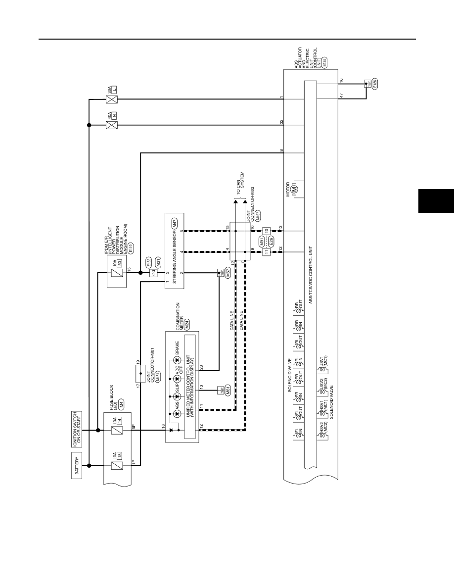
BRAKE CONTROL SYSTEM - VDC
WIRING DIAGRAM
BRAKE CONTROL SYSTEM - VDC
Wiring Diagram - With VQ40DE
INFOID:0000000007356793
ABFWA0267GB
August 2012
2012 Pathfinder
BRAKE CONTROL SYSTEM - VDC
BRC-89
< WIRING DIAGRAM >
[TYPE 1]
C
D
E
G
H
I
J
K
L
M
A
B
BRC
N
O
P
ABFWA0268GB
August 2012
2012 Pathfinder
Нет комментариевНе стесняйтесь поделиться с нами вашим ценным мнением.
Текст