Nissan Pathfinder (2012 year). Instruction — part 264
P0172, P0175 FUEL INJECTION SYSTEM FUNCTION
EC-193
< DTC/CIRCUIT DIAGNOSIS >
[VQ40DE]
C
D
E
F
G
H
I
J
K
L
M
A
EC
N
P
O
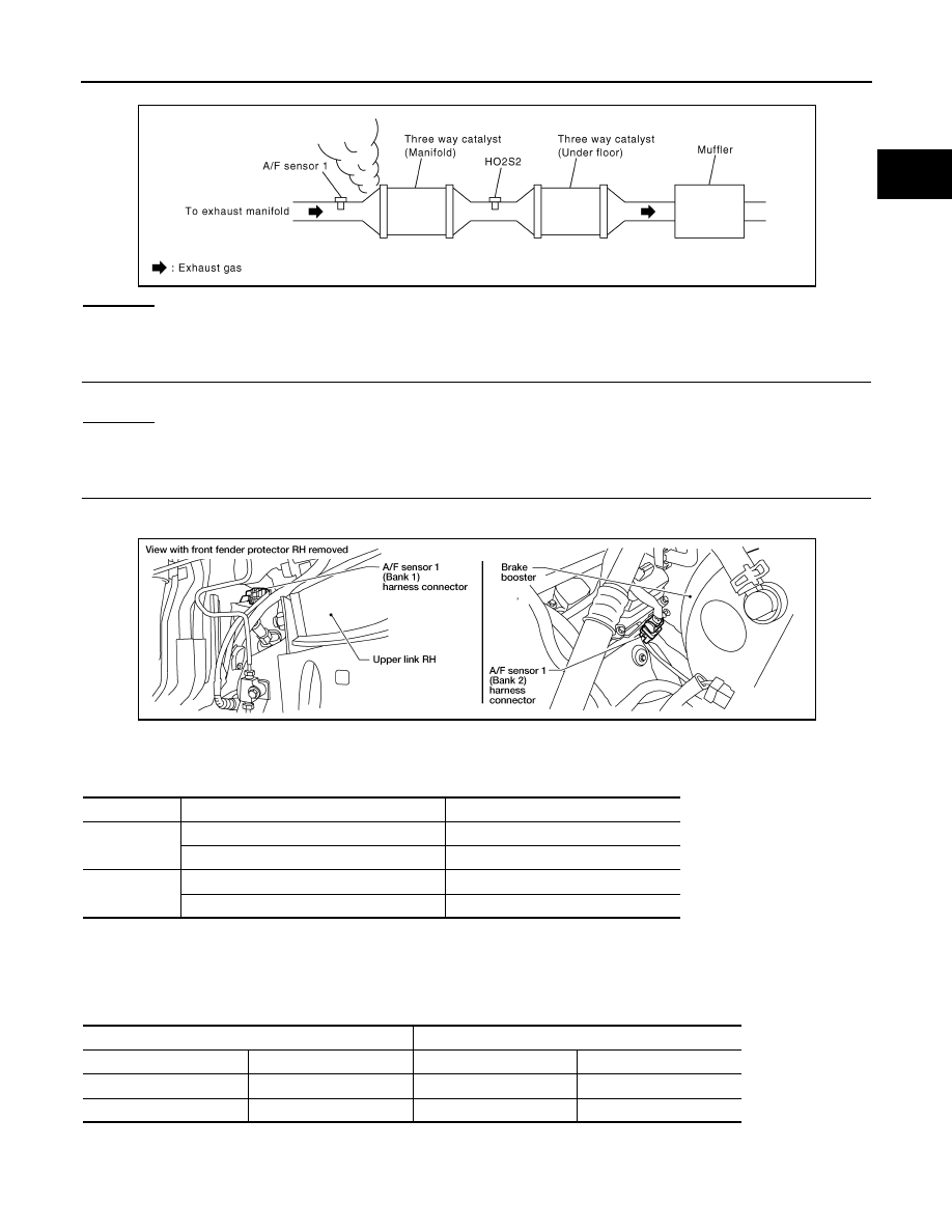
2. Listen for an exhaust gas leak before three way catalyst (manifold).
OK or NG
OK
>> GO TO 2.
NG
>> Repair or replace.
2.
CHECK FOR INTAKE AIR LEAK
Listen for an intake air leak after the mass air flow sensor.
OK or NG
OK
>> GO TO 3.
NG
>> Repair or replace.
3.
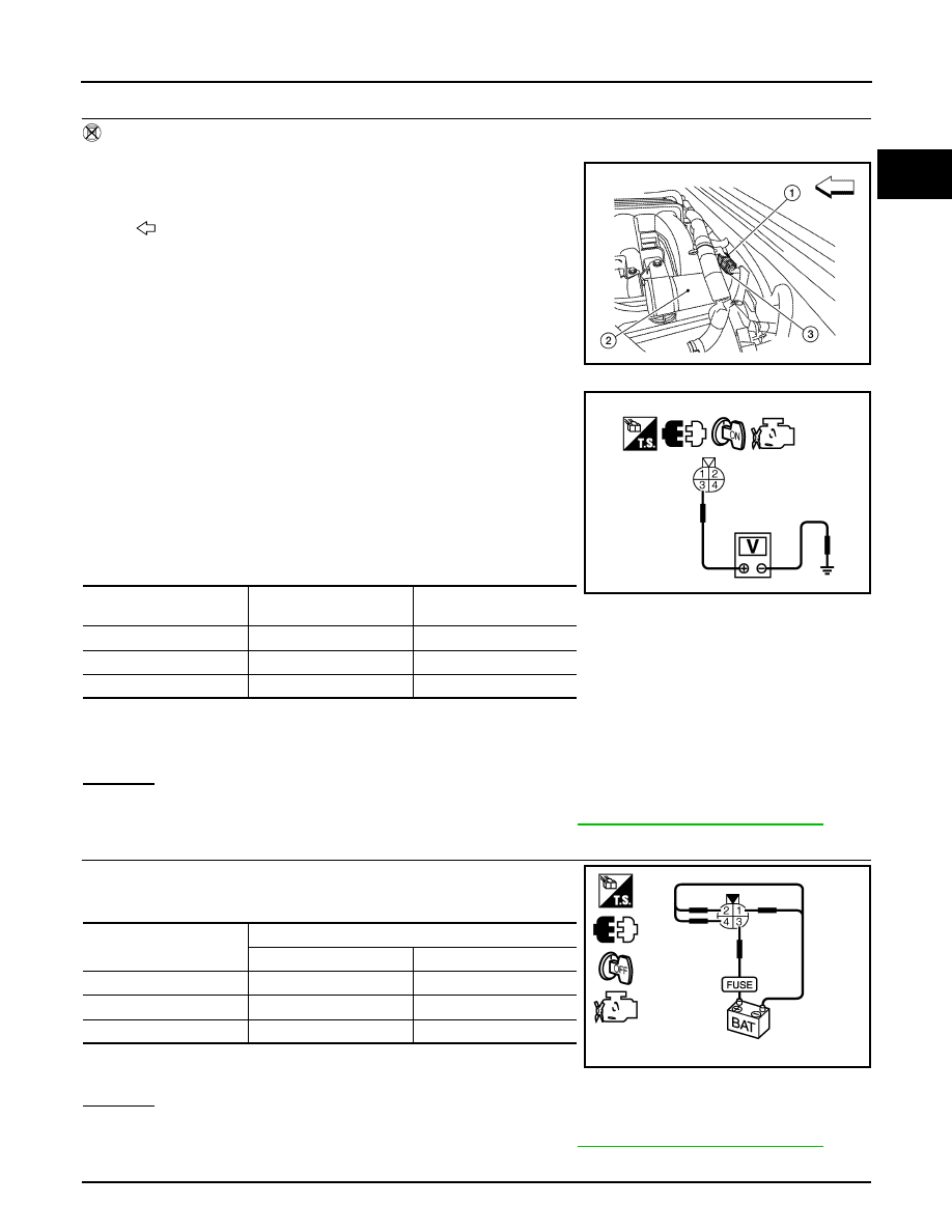
CHECK A/F SENSOR 1 INPUT SIGNAL CIRCUIT
1. Turn ignition switch OFF.
2. Disconnect corresponding A/F sensor 1 harness connector.
3. Disconnect ECM harness connector.
4. Check harness continuity between A/F sensor 1 terminal and ECM terminal as follows.
Refer to Wiring Diagram.
5. Check harness continuity between the following terminals and ground.
Refer to Wiring Diagram.
6. Also check harness for short to power.
PBIB1216E
A/F sensor 1 terminal
ECM terminal
Bank 1
1
35
2
56
Bank 2
1
16
2
75
Continuity should exist.
Bank 1
Bank 2
A/F sensor 1 terminal
ECM terminal
A/F sensor 1 terminal
ECM terminal
1
35
1
16
2
56
2
75
Continuity should not exist.
BBIA0544E
August 2012
2012 Pathfinder

EC-194
< DTC/CIRCUIT DIAGNOSIS >
[VQ40DE]
P0172, P0175 FUEL INJECTION SYSTEM FUNCTION
OK or NG
OK
>> GO TO 4.
NG
>> Repair open circuit or short to ground or short to power in harness or connectors.
4.
CHECK FUEL PRESSURE
1. Release fuel pressure to zero. Refer to
2. Install fuel pressure gauge and check fuel pressure. Refer to
OK or NG
OK (With CONSULT)>>GO TO 6.
OK (Without CONSULT)>>GO TO 7.
NG
>> GO TO 5.
5.
DETECT MALFUNCTIONING PART
Check the following.
• Fuel pump and circuit (Refer to,
.)
• Fuel pressure regulator (Refer to
>> Repair or replace.
6.
CHECK MASS AIR FLOW SENSOR
With CONSULT
1. Install all removed parts.
2. Check “MASS AIR FLOW” in “DATA MONITOR” mode with CONSULT.
OK or NG
OK
>> GO TO 8.
NG
>> Check connectors for rusted terminals or loose connections in the mass air flow sensor circuit or
ground. Refer to
EC-113, "Component Description"
.
7.
CHECK MASS AIR FLOW SENSOR
With GST
1. Install all removed parts.
2. Check mass air flow sensor signal in Service $01 with GST.
OK or NG
OK (P0172)>>GO TO 9.
OK (P0175)>>GO TO 11.
NG
>> Check connectors for rusted terminals or loose connections in the mass air flow sensor circuit or
ground. Refer to
EC-113, "Component Description"
.
8.
CHECK FUNCTION OF FUEL INJECTOR
With CONSULT
1. Start engine.
2. Perform “POWER BALANCE” in “ACTIVE TEST” mode with CONSULT.
3. Make sure that each circuit produces a momentary engine speed drop.
OK or NG
OK
>> GO TO 12.
NG
>> Perform trouble diagnosis for FUEL INJECTOR, refer to
EC-402, "Component Description"
At idling: 350 kPa (3.57 kg/cm
2
, 51 psi)
2.0 - 6.0 g/s:
at idling
7.0 - 20.0 g/s:
at 2,500 rpm
2.0 - 6.0 g/s:
at idling
7.0 - 20.0 g/s:
at 2,500 rpm
August 2012
2012 Pathfinder
P0172, P0175 FUEL INJECTION SYSTEM FUNCTION
EC-195
< DTC/CIRCUIT DIAGNOSIS >
[VQ40DE]
C
D
E
F
G
H
I
J
K
L
M
A
EC
N
P
O
9.
CHECK FUNCTION OF FUEL INJECTOR-I
Without CONSULT
1. Stop engine.
2. Disconnect harness connector F44 (3), F201 (1)
3. Turn ignition switch ON.
4. Check voltage between harness connector F44 terminal 3 and
ground with CONSULT or tester.
5. Turn ignition switch OFF.
6. Disconnect ECM harness connector.
7. Check harness continuity between harness connector F44 and
ECM as follows.
Refer to Wiring Diagram.
8. Also check harness for short to ground and short to power.
OK or NG
OK
>> GO TO 10.
NG
>> Perform trouble diagnosis for FUEL INJECTOR, refer to
EC-402, "Component Description"
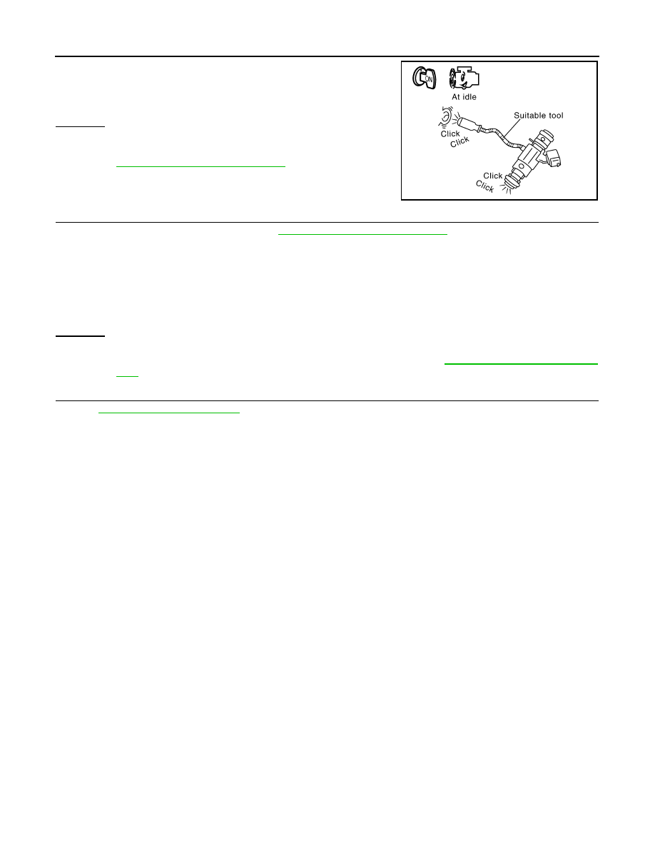
10.
CHECK FUNCTION OF FUEL INJECTOR-II
Provide battery voltage between harness connector F201 as follows
and then interrupt it. Listen to each fuel injector operating sound.
OK or NG
OK
>> GO TO 12.
NG
>> Perform trouble diagnosis for FUEL INJECTOR, refer to
EC-402, "Component Description"
11.
CHECK FUNCTION OF FUEL INJECTOR
2
: Vacuum tank
: Front
AWBIA0686ZZ
Voltage: Battery voltage
Cylinder
Harness connector F44
terminal
ECM terminal
1
2
23
3
1
22
5
4
21
Continuity should exist.
PBIB2633E
Cylinder
Harness connector F201 terminal
(+)
(–)
1
3
2
3
3
1
5
3
4
Operating sound should exist.
PBIB2634E
August 2012
2012 Pathfinder
EC-196
< DTC/CIRCUIT DIAGNOSIS >
[VQ40DE]
P0172, P0175 FUEL INJECTION SYSTEM FUNCTION
1. Start engine.
2. Listen to fuel injectors No.2, No.4, No.6 operating sound.
OK or NG
OK
>> GO TO 12.
NG
>> Perform trouble diagnosis for FUEL INJECTOR, refer to
EC-402, "Component Description"
.
12.
CHECK FUEL INJECTOR
1. Remove fuel injector assembly. Refer to
EM-47, "Removal and Installation"
.
Keep fuel hose and all fuel injectors connected to fuel tube.
2. Confirm that the engine is cooled down and there are no fire hazards near the vehicle.
3. Disconnect all fuel injector harness connectors.
4. Disconnect all ignition coil harness connectors.
5. Prepare pans or saucers under each fuel injector.
6. Crank engine for about 3 seconds.
Make that sure fuel does not drip from fuel injector.
OK or NG
OK (Does not drip.)>>GO TO 13.
NG (Drips.)>>Replace the fuel injectors from which fuel is dripping. Refer to
. Always replace O-ring with new one.
13.
CHECK INTERMITTENT INCIDENT
GI-37, "Intermittent Incident"
>>
INSPECTION END
Clicking noise should exist.
PBIB1986E
August 2012
2012 Pathfinder
P0181 FTT SENSOR
EC-197
< DTC/CIRCUIT DIAGNOSIS >
[VQ40DE]
C
D
E
F
G
H
I
J
K
L
M
A
EC
N
P
O
P0181 FTT SENSOR
Component Description
INFOID:0000000007358107
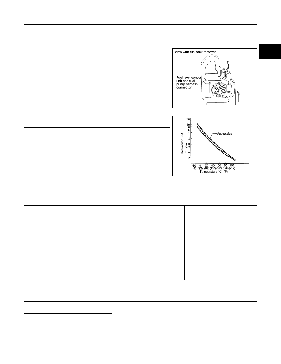
The fuel tank temperature sensor is used to detect the fuel tempera-
ture inside the fuel tank. The sensor modifies a voltage signal from
the ECM. The modified signal returns to the ECM as the fuel temper-
ature input. The sensor uses a thermistor which is sensitive to the
change in temperature. The electrical resistance of the thermistor
decreases as temperature increases.
<Reference data>
*: This data is reference value and is measured between ECM terminal 107 (fuel tank
temperature sensor) and 116 (ECM ground).
CAUTION:
Never use ECM ground terminals when measuring input/output
voltage. Doing so may result in damage to the ECM's transistor.
Use a ground other than ECM terminals, such as the ground.
On Board Diagnosis Logic
INFOID:0000000007358108
DTC Confirmation Procedure
INFOID:0000000007358109
1.
INSPECTION START
Is it necessary to erase permanent DTC?
YES
>> GO TO 7.
NO
>> GO TO 2.
2.
PRECONDITIONING
If DTC Confirmation Procedure has been previously conducted, always perform the following before conduct-
ing the next test.
BBIA0545E
Fluid temperature
°
C (
°
F)
Voltage*
V
Resistance
k
Ω
20 (68)
3.5
2.3 - 2.7
50 (122)
2.2
0.79 - 0.90
SEF012P
DTC No.
Trouble diagnosis name
DTC detecting condition
Possible cause
P0181
Fuel tank temperature sensor
circuit range/performance
A)
Rationally incorrect voltage from the
sensor is sent to ECM, compared with
the voltage signals from engine coolant
temperature sensor and intake air tem-
perature sensor.
• Harness or connectors
(The sensor circuit is open or shorted)
• Fuel tank temperature sensor
B)
The comparison result of signals trans-
mitted to ECM from each temperature
sensor (IAT sensor, ECT sensor, and
FTT sensor) shows that the voltage
signal of the FTT sensor is higher/low-
er than that of other temperature sen-
sors when the engine is started with its
cold state.
• Harness or connectors
(High or low resistance in the FTT
sensor circuit)
• FTT sensor
August 2012
2012 Pathfinder

EC-198
< DTC/CIRCUIT DIAGNOSIS >
[VQ40DE]
P0181 FTT SENSOR
1. Turn ignition switch OFF and wait at least 10 seconds.
2. Turn ignition switch ON.
3. Turn ignition switch OFF and wait at least 10 seconds.
>> GO TO 3.
3.
PERFORM DTC CONFIRMATION PROCEDURE FOR MALFUNCTION A-I
1. Turn ignition switch ON and wait at least 10 seconds.
2. Check 1st trip DTC.
Is 1st trip DTC detected?
YES
>> Go to
NO
>> GO TO 4.
4.
CHECK ENGINE COOLANT TEMPERATURE
With CONSULT
1. Select “COOLAN TEMP/S” in “DATA MONITOR” mode with CONSULT.
2. Check “COOLAN TEMP/S” indication.
With GST
Follow the procedure “With CONSULT” above.
Is “COOLAN TEMP/S” indication less than 60
°
C (140
°
F)?
YES
>> INSPECTION END
NO
>> GO TO 5.
5.
PERFORM DTC CONFIRMATION PROCEDURE FOR MALFUNCTION A-II
With CONSULT
1. Cool engine down until “COOLAN TEMP/S” indication is less than 60
°
C (140
°
F).
2. Wait at least 10 seconds.
3. Check 1st trip DTC.
With GST
Follow the procedure “With CONSULT” above.
Is 1st trip DTC detected?
YES
>> Go to
NO
>> GO TO 6.
6.
PERFORM COMPONENT FUNCTION CHECK (FOR MALFUNCTION B)
Perform component function check. Refer to
EC-199, "Component Function Check"
NOTE:
Use the component function check to check the overall function of the FTT sensor circut. During this check, a
1st trip DTC might not be confirmed.
Is the inspection result normal?
YES
>> INSPECTION END
NO
>> Proceed to
.
7.
PRECONDITIONING
If DTC CONFIRMATION PROCEDURE has been previously conducted, always perform the following proce-
dure before conducting the next test.
1. Turn ignition switch OFF and wait at least 10 seconds.
2. Turn ignition switch ON.
3. Turn ignition switch OFF and wait at least 10 seconds.
TESTING CONDITION:
•
Before performing the following procedure, do not add fuel.
•
Before performing the following procedure, check that fuel level is between 1/4 and 4/4.
•
Before performing the following procedure, confirm that battery voltage is 11 V or more at idle.
>> GO TO 8.
8.
PERFORM DTC CONFIRMATION PROCEDURE B
1. Start engine and let it idle for 60 minutes.
August 2012
2012 Pathfinder
P0181 FTT SENSOR
EC-199
< DTC/CIRCUIT DIAGNOSIS >
[VQ40DE]
C
D
E
F
G
H
I
J
K
L
M
A
EC
N
P
O
2. Move the vehicle to a cool place.
NOTE:
Cool the vehicle in an environment of ambient air temperature between
−
10
°
C (14
°
F) and 35
°
C (95
°
F).
3. Turn ignition switch OFF and soak the vehicle for 12 hours.
CAUTION:
Never turn ignition switch ON during soaking.
NOTE:
The vehicle must be cooled with the food open.
4. Start engine and let it idle for 5 minutes or more.
CAUTION:
Never turn ignition switch OFF during idling.
5. Check 1st trip DTC.
Is 1st trip DTC detected?
YES
>> Proceed to
.
NO
>> INSPECTION END
Component Function Check
INFOID:0000000007358110
1.
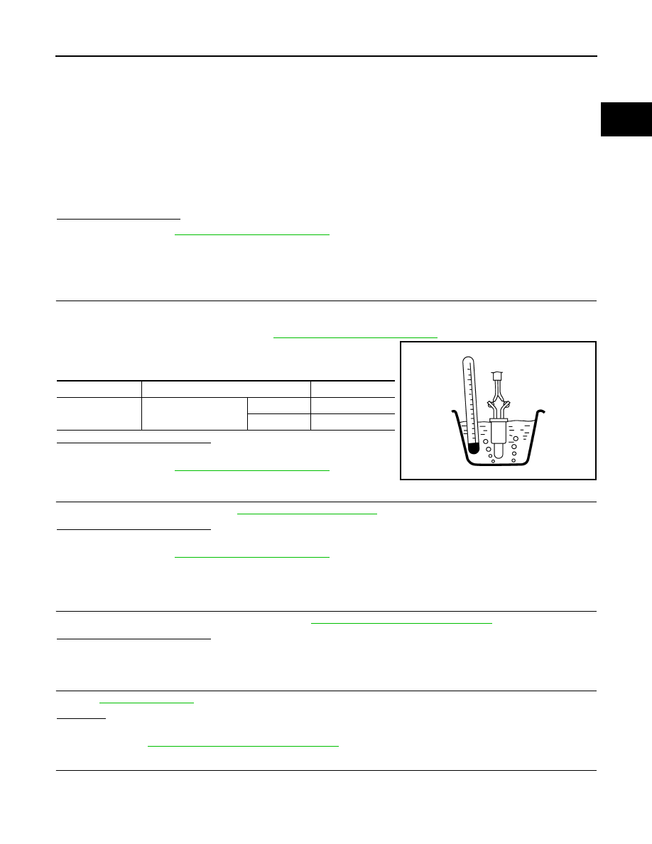
CHECK FUEL TANK TEMPERATURE (FTT) SENSOR
1. Turn ignition switch OFF.
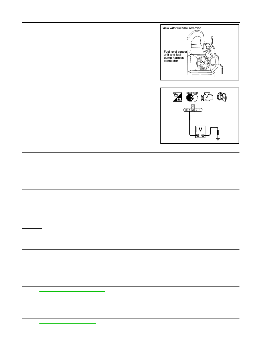
2. Disconnect fuel level sensor unit and fuel pump harness connector.
3. Remove fuel level sensor unit. Refer to
FL-11, "Removal and Installation"
.
4. Check resistance between fuel level sensor unit and fuel pump
terminals by heating with hot water as shown in the figure.
Is the inspection result normal?
YES
>> GO TO 2.
NO
>> Proceed to
.
2.
CHECK INTERMITTENT INCIDENT
Check intermittent incident. Refer to
GI-37, "Intermittent Incident"
.
Is the inspection result normal?
YES
>> INSPECTION END
NO
>> Proceed to
.
Diagnosis Procedure
INFOID:0000000007358111
1.
INSPECTION START
Confirm the detected malfunction (A or B). Refer to
EC-197, "On Board Diagnosis Logic"
.
Which malfunction is detected?
A
>> GO TO 2.
B
>> GO TO 7.
2.
CHECK COMBINATION METER FUNCTION
.
OK or NG
OK
>> GO TO 3.
NG
>> Go to
MWI-34, "Component Function Check"
.
3.
CHECK FUEL TANK TEMPERATURE SENSOR POWER SUPPLY CIRCUIT
1. Turn ignition switch OFF.
Terminals
Condition
Resistance (k
Ω
)
2 and 4
Temperature [
°
C (
°
F)]
20 (68)
2.3 – 2.7
50 (122)
0.79 – 0.90
JMBIA0167ZZ
August 2012
2012 Pathfinder
EC-200
< DTC/CIRCUIT DIAGNOSIS >
[VQ40DE]
P0181 FTT SENSOR
2. Disconnect “fuel level sensor unit and fuel pump” harness con-
nector.
3. Turn ignition switch ON.
4. Check voltage between “fuel level sensor unit and fuel pump”
terminal 4 and ground with CONSULT or tester.
OK or NG
OK
>> GO TO 5.
NG
>> GO TO 4.
4.
DETECT MALFUNCTIONING PART
Check the following.
• Harness connectors E41, C1
• Harness for open or short between ECM and “fuel level sensor unit and fuel pump”
>> Repair harness or connector.
5.
CHECK FUEL TANK TEMPERATURE SENSOR GROUND CIRCUIT FOR OPEN AND SHORT
1. Turn ignition switch OFF.
2. Check harness continuity between “fuel level sensor unit and fuel pump” terminal 3 and ground. Refer to
Wiring Diagram.
3. Also check harness for short to power.
OK or NG
OK
>> GO TO 7.
NG
>> GO TO 6.
6.
DETECT MALFUNCTIONING PART
Check the following.
• Harness connectors E41, C1
• Harness for open or short between “fuel level sensor unit and fuel pump” ground
>> Repair open circuit or short to power in harness or connector.
7.
CHECK FUEL TANK TEMPERATURE SENSOR
EC-201, "Component Inspection"
OK or NG
OK
>> GO TO 8.
NG
>> Replace fuel level sensor unit. Refer to
FL-11, "Removal and Installation"
8.
CHECK INTERMITTENT INCIDENT
GI-37, "Intermittent Incident"
BBIA0545E
Voltage: Approximately 5V
PBIB0932E
Continuity should exist.
August 2012
2012 Pathfinder
Нет комментариевНе стесняйтесь поделиться с нами вашим ценным мнением.
Текст