Nissan Pathfinder (2012 year). Instruction — part 111
BRC-154
< DTC/CIRCUIT DIAGNOSIS >
[TYPE 2]
C1111 ABS MOTOR, MOTOR RELAY SYSTEM
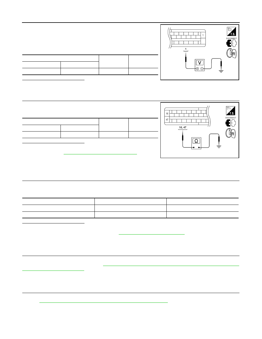
1. Turn ignition switch OFF.
2. Disconnect ABS actuator and electric unit (control unit) connec-
tor.
3. Check voltage between the ABS actuator and electric unit (con-
trol unit) connector E127 terminal 1 and ground.
Is the inspection result normal?
YES
>> GO TO 3
NO
>> Repair or replace malfunctioning components.
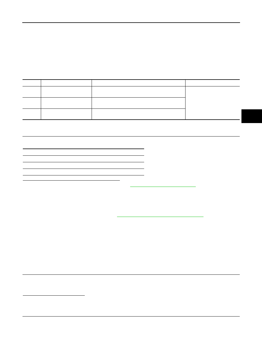
3.
CHECK ABS ACTUATOR AND ELECTRIC UNIT (CONTROL UNIT) GROUND CIRCUIT
Check continuity between ABS actuator and electric unit (control
unit) connector E127 terminals 16, 47 and ground.
Is the inspection result normal?
YES
>> Replace ABS actuator and electric unit (control unit).
BRC-231, "Removal and Installation"
NO
>> Repair or replace malfunctioning components.
Component Inspection
INFOID:0000000007356864
1.
CHECK ACTIVE TEST
1. On “ACTIVE TEST”, select “ABS MOTOR”.
2. Touch On and Off on screen. Make sure motor relay and actuator relay operates as shown in table below.
Is the inspection result normal?
YES
>> Inspection End.
NO
>> Go to diagnosis procedure. Refer to
BRC-153, "Diagnosis Procedure"
Special Repair Requirement
INFOID:0000000007818491
1.
ADJUSTMENT OF STEERING ANGLE SENSOR NEUTRAL POSITION
Always perform neutral position adjustment for the steering angle sensor when replacing the ABS actuator
and electric unit (control unit). Refer to
BRC-121, "ADJUSTMENT OF STEERING ANGLE SENSOR NEU-
>> GO TO 2
2.
CALIBRATION OF DECEL G SENSOR
Always perform calibration of decel G sensor when replacing the ABS actuator and electric unit (control unit).
BRC-122, "CALIBRATION OF DECEL G SENSOR : Description"
.
>> END
ABS actuator and electric unit (control unit)
—
Voltage
Connector
Terminal
E127
1
Ground
Battery voltage
AWFIA0017ZZ
ABS actuator and electric unit (control unit)
—
Continuity
Connector
Terminal
E127
16, 47
Ground
Yes
AWFIA0016ZZ
Operation
On
Off
MOTOR RELAY
On
Off
ACTUATOR RLY
On
On
August 2012
2012 Pathfinder
C1113, C1145, C1146 YAW RATE/SIDE/DECEL G SENSOR
BRC-155
< DTC/CIRCUIT DIAGNOSIS >
[TYPE 2]
C
D
E
G
H
I
J
K
L
M
A
B
BRC
N
O
P
C1113, C1145, C1146 YAW RATE/SIDE/DECEL G SENSOR
Description
INFOID:0000000007356866
The yaw rate/side/decel G sensor detects the yaw rate/side/decel G affecting the vehicle, and transmits the
data to the ABS actuator and electric unit (control unit) as an analog voltage signal.
DTC Logic
INFOID:0000000007356867
DTC DETECTION LOGIC
DTC CONFIRMATION PROCEDURE
1.
CHECK SELF-DIAGNOSIS RESULTS
Check the self-diagnosis results.
Is above displayed on the self-diagnosis display?
YES
>> Proceed to diagnosis procedure. Refer to
BRC-155, "Diagnosis Procedure"
NO
>> Inspection End.
Diagnosis Procedure
INFOID:0000000007356868
Regarding Wiring Diagram information, refer to
BRC-207, "Wiring Diagram - With VK56DE"
CAUTION:
• Sudden turns (such as spin turns, acceleration turns), drifting, etc. when VDC function is OFF may
cause the yaw rate/side/decel G sensor system to indicate a malfunction. This is not a malfunction if
normal operation can be resumed after restarting the engine.
• If vehicle is on turn table at entrance to parking garage, or on other moving surface, SLIP indicator
lamp may illuminate and CONSULT self-diagnosis may indicate yaw rate sensor system malfunction.
However, in this case there is no malfunction in yaw rate sensor system. Take vehicle off of turn
table or other moving surface, and start engine. Results will return to normal.
1.
CONNECTOR INSPECTION
1. Disconnect the ABS actuator and electric unit (control unit) connector and yaw rate/side/decel G sensor
connector.
2. Check the terminals for deformation, disconnection, looseness or damage.
Is the inspection result normal?
YES
>> GO TO 2
NO
>> Repair or replace as necessary.
2.
YAW RATE/SIDE/DECEL G SENSOR HARNESS INSPECTION
Check continuity between the ABS actuator and electric unit (control unit) connector E127 and the yaw rate/
side/decel G sensor connector B73.
DTC
Display item
Malfunction detected condition
Possible cause
C1113
G-SENSOR
Longitudinal G-sensor is malfunctioning, or signal line of
longitudinal G-sensor is open or shorted.
• Harness or connector
• ABS actuator and electric unit
(control unit)
• Yaw rate/side/decel G sensor
C1145
YAW RATE SENSOR
Yaw rate sensor is malfunctioning, or the yaw rate sensor
signal line is open or shorted.
C1146
SIDE G-SEN CIRCUIT
Side G sensor is malfunctioning, or circuit of side G sen-
sor is open or shorted.
Self-diagnosis results
G-SENSOR
YAW RATE SENSOR
SIDE G-SEN CIRCUIT
August 2012
2012 Pathfinder

BRC-156
< DTC/CIRCUIT DIAGNOSIS >
[TYPE 2]
C1113, C1145, C1146 YAW RATE/SIDE/DECEL G SENSOR
Is the inspection result normal?
YES
>> GO TO 3
NO
>> Repair or replace as necessary.
3.
YAW RATE/SIDE/DECEL G SENSOR INSPECTION
1. Connect the yaw rate/side/decel G sensor connector and ABS actuator and electric unit (control unit) con-
nector.
2. Perform yaw rate/side/decel G sensor component inspection. Refer to
BRC-156, "Component Inspection"
.
Is the inspection result normal?
YES
>> Perform self-diagnosis again. If the same results appear, replace the ABS actuator and electric
unit (control unit). Refer to
BRC-231, "Removal and Installation"
.
NO
>> Replace the yaw rate/side/decel G sensor. Refer to
BRC-234, "Removal and Installation"
.
Component Inspection
INFOID:0000000007356869
1.
CHECK DATA MONITOR
Select “YAW RATE SEN”, “SIDE G-SENSOR”, “DECEL G-SEN” in “DATA MONITOR” and check yaw rate/
side/decel G sensor signal.
Is the inspection result normal?
YES
>> Inspection End.
NO
>> Replace the yaw rate/side/decel G sensor. Refer to
BRC-234, "Removal and Installation"
.
Special Repair Requirement
INFOID:0000000007818492
1.
ADJUSTMENT OF STEERING ANGLE SENSOR NEUTRAL POSITION
Always perform neutral position adjustment for the steering angle sensor when replacing the ABS actuator
and electric unit (control unit). Refer to
BRC-121, "ADJUSTMENT OF STEERING ANGLE SENSOR NEU-
>> GO TO 2
2.
CALIBRATION OF DECEL G SENSOR
Always perform calibration of decel G sensor when replacing the ABS actuator and electric unit (control unit).
BRC-122, "CALIBRATION OF DECEL G SENSOR : Description"
.
>> END
ABS actuator and electric unit (control unit)
Yaw rate/side/decel G sensor
Continuity
Connector
Terminal
Connector
Terminal
E127
6
B73
4
Yes
24
1
25
2
29
3
Vehicle condition
YAW RATE SEN
(DATA MONITOR)
SIDE G-SENSOR
(DATA MONITOR)
DECEL G-SEN
(DATA MONITOR)
Stopped
-4 to +4 deg/s
-1.1 to +1.1 m/s
-0.11 G to +0.11 G
Turning right
Negative value
Negative value
-
Turning left
Positive value
Positive value
-
Speed up
-
-
Negative value
Speed down
-
-
Positive value
August 2012
2012 Pathfinder

C1115 WHEEL SENSOR
BRC-157
< DTC/CIRCUIT DIAGNOSIS >
[TYPE 2]
C
D
E
G
H
I
J
K
L
M
A
B
BRC
N
O
P
C1115 WHEEL SENSOR
Description
INFOID:0000000007356871
When the sensor rotor rotates, the magnetic field changes. It converts the magnetic field changes to current
signals (rectangular wave) and transmits them to the ABS actuator and electric unit (control unit).
DTC Logic
INFOID:0000000007356872
DTC DETECTION LOGIC
DTC CONFIRMATION PROCEDURE
1.
CHECK SELF-DIAGNOSIS RESULTS
Check the self-diagnosis results.
Is above displayed on the self-diagnosis display?
YES
>> Proceed to diagnosis procedure. Refer to
BRC-157, "Diagnosis Procedure"
NO
>> Inspection End.
Diagnosis Procedure
INFOID:0000000007818486
Regarding Wiring Diagram information, refer to
BRC-207, "Wiring Diagram - With VK56DE"
CAUTION:
Do not check between wheel sensor terminals.
1.
CONNECTOR INSPECTION
1. Disconnect the ABS actuator and electric unit (control unit) connector and wheel sensor connector of mal-
functioning code.
2. Check the terminals for deformation, disconnection, looseness or damage.
Is the inspection result normal?
YES
>> GO TO 2
NO
>> Repair or replace as necessary.
2.
CHECK WHEEL SENSOR OUTPUT SIGNAL
1. Connect ABS active wheel sensor tester (J-45741) to wheel sensor using appropriate adapter.
2. Turn on the ABS active wheel sensor tester power switch.
NOTE:
The green POWER indicator should illuminate. If the POWER indicator does not illuminate, replace the
battery in the ABS active wheel sensor tester before proceeding.
3. Spin the wheel of the vehicle by hand and observe the red SENSOR indicator on the ABS active wheel
sensor tester. The red SENSOR indicator should flash on and off to indicate an output signal.
NOTE:
If the red SENSOR indicator illuminates but does not flash, reverse the polarity of the tester leads and
retest.
Does the ABS active wheel sensor tester detect a signal?
YES
>> GO TO 3
NO
>> Replace the wheel sensor. Refer to
BRC-229, "Removal and Installation"
.
DTC
Display item
Malfunction detected condition
Possible cause
C1115
ABS SENSOR
[ABNORMAL SIGNAL]
When wheel sensor input signal is malfunctioning.
• Harness or connector
• Wheel sensor
• ABS actuator and electric unit
(control unit)
Self-diagnosis results
ABS SENSOR [ABNORMAL SIGNAL]
August 2012
2012 Pathfinder
BRC-158
< DTC/CIRCUIT DIAGNOSIS >
[TYPE 2]
C1115 WHEEL SENSOR
3.
CHECK TIRES
Check the inflation pressure, wear and size of each tire.
Is the inspection result normal?
YES
>> GO TO 4
NO
>> Adjust tire pressure or replace tire(s).
4.
CHECK WHEEL BEARINGS
Check wheel bearing axial end play. Refer to
FAX-6, "On-Vehicle Inspection and Service"
"On-Vehicle Inspection and Service"
(rear).
Is the inspection result normal?
YES
>> GO TO 5
NO
>> Repair or replace as necessary. Refer to
FAX-10, "Removal and Installation"
(rear).
5.
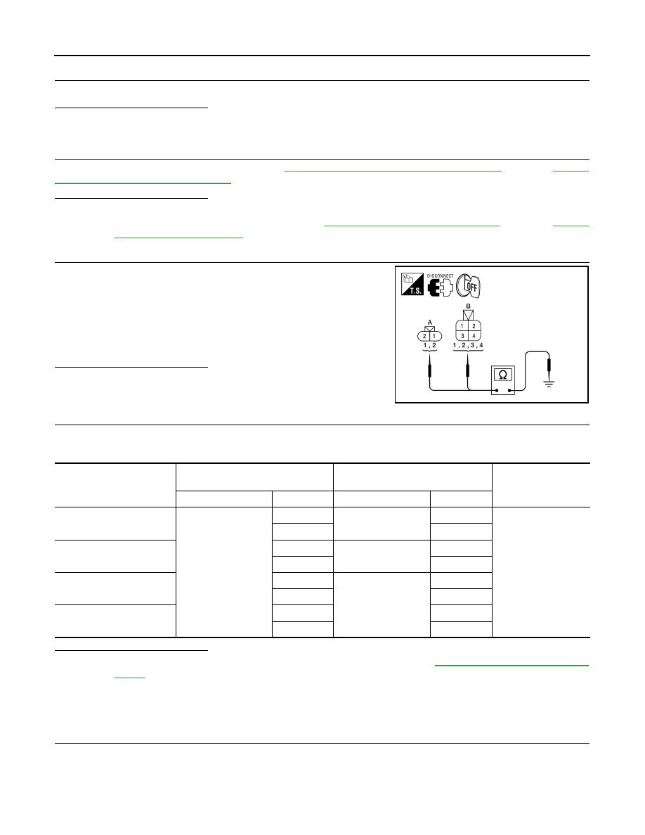
CHECK WIRING HARNESS FOR SHORT CIRCUIT
1. Disconnect ABS actuator and electric unit (control unit) connec-
tor and wheel sensor connector of malfunction code No.
2. Check continuity between front wheel sensor connector termi-
nals (A) or rear wheel sensor connector terminals (B) and
ground.
Is the inspection result normal?
YES
>> GO TO 6
NO
>> Repair the circuit.
6.
CHECK WIRING HARNESS FOR OPEN CIRCUIT
1. Check continuity between ABS actuator and electric unit (control unit) connector and the malfunctioning
wheel sensor connector.
Is the inspection result normal?
YES
>> Replace the ABS actuator and electric unit (control unit). Refer to
.
NO
>> Repair the circuit.
Component Inspection
INFOID:0000000007818487
1.
CHECK DATA MONITOR
On “DATA MONITOR”, select “FR LH SENSOR”, “FR RH SENSOR”, “RR LH SENSOR”, and “RR RH SEN-
SOR”, and check the vehicle speed.
Continuity should not exist.
AWFIA0464ZZ
Wheel sensor
ABS actuator and
electric unit (control unit)
Wheel sensor
Continuity
Connector
Terminal
Connector
Terminal
Front LH
E127
45
E18
1
Yes
46
2
Front RH
34
E117
1
33
2
Rear LH
37
C13
3
36
4
Rear RH
42
1
43
2
August 2012
2012 Pathfinder

C1115 WHEEL SENSOR
BRC-159
< DTC/CIRCUIT DIAGNOSIS >
[TYPE 2]
C
D
E
G
H
I
J
K
L
M
A
B
BRC
N
O
P
Is the inspection result normal?
YES
>> Inspection End.
NO
>> Go to diagnosis procedure. Refer to
BRC-157, "Diagnosis Procedure"
.
Special Repair Requirement
INFOID:0000000007818488
1.
ADJUSTMENT OF STEERING ANGLE SENSOR NEUTRAL POSITION
Always perform neutral position adjustment for the steering angle sensor when replacing the ABS actuator
and electric unit (control unit). Refer to
BRC-121, "ADJUSTMENT OF STEERING ANGLE SENSOR NEU-
>> GO TO 2
2.
CALIBRATION OF DECEL G SENSOR
Always perform calibration of decel G sensor when replacing the ABS actuator and electric unit (control unit).
BRC-122, "CALIBRATION OF DECEL G SENSOR : Description"
.
>> END
Wheel sensor
Vehicle speed (DATA MONITOR)
FR LH SENSOR
Nearly matches the speedometer dis-
play (
±
10% or less)
FR RH SENSOR
RR LH SENSOR
RR RH SENSOR
August 2012
2012 Pathfinder
BRC-160
< DTC/CIRCUIT DIAGNOSIS >
[TYPE 2]
C1116 STOP LAMP SWITCH
C1116 STOP LAMP SWITCH
Description
INFOID:0000000007356876
The stop lamp switch transmits the stop lamp switch signal (ON/OFF) to the ABS actuator and electric unit
(control unit).
DTC Logic
INFOID:0000000007356877
DTC DETECTION LOGIC
DTC CONFIRMATION PROCEDURE
1.
CHECK SELF-DIAGNOSIS RESULTS
Check the self-diagnosis results.
Is above displayed on the self-diagnosis display?
YES
>> Proceed to diagnosis procedure. Refer to
BRC-160, "Diagnosis Procedure"
.
NO
>> Inspection End.
Diagnosis Procedure
INFOID:0000000007356878
Regarding Wiring Diagram information, refer to
BRC-207, "Wiring Diagram - With VK56DE"
1.
CONNECTOR INSPECTION
1. Disconnect ABS actuator and electric unit (control unit) connector and stop lamp switch connector.
2. Check the terminals for deformation, disconnection, looseness or damage.
Is the inspection result normal?
YES
>> GO TO 2
NO
>> Repair or replace as necessary.
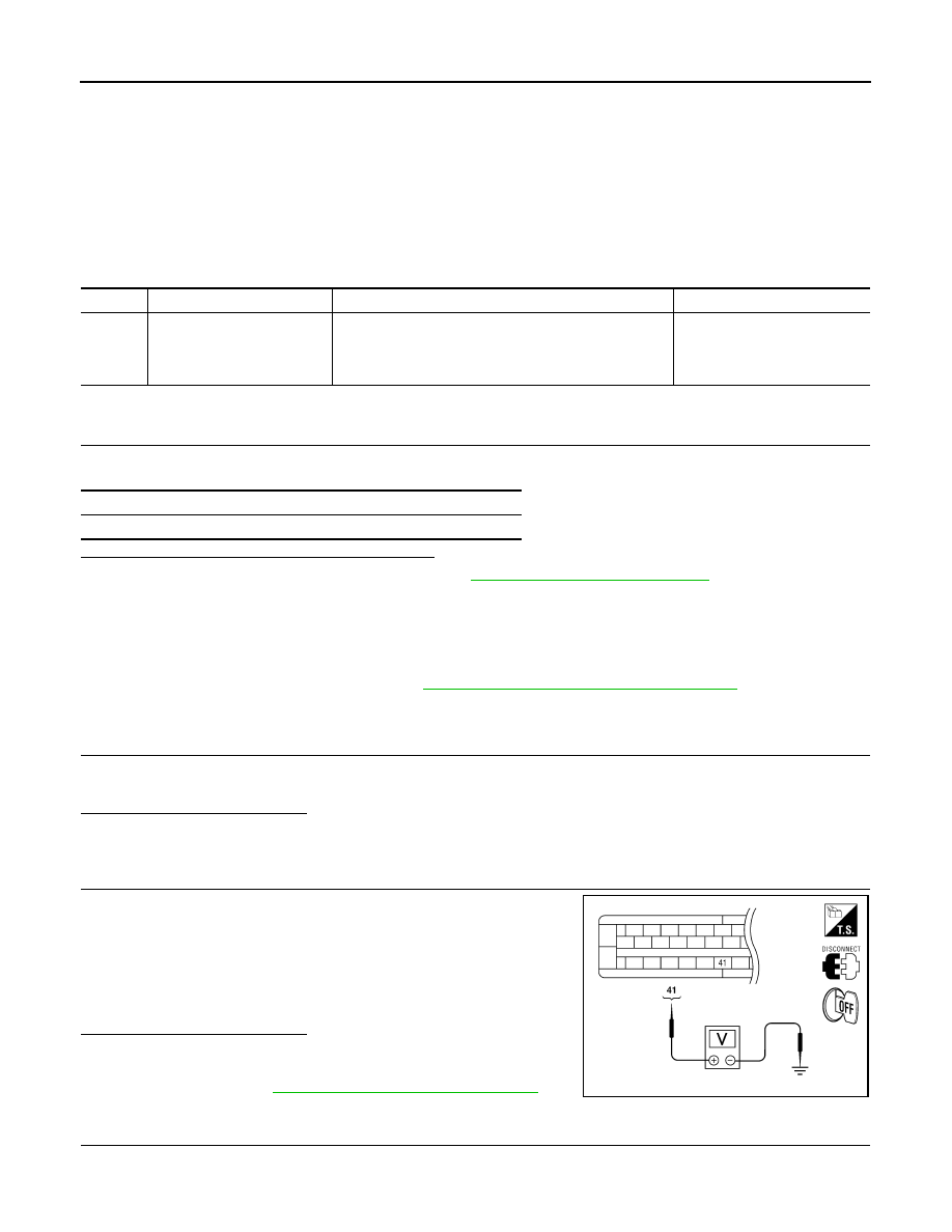
2.
STOP LAMP SWITCH INSPECTION
Check voltage between ABS actuator and electric unit (control unit)
connector E127 terminal 41 and body ground.
Is the inspection result normal?
YES
>> Perform self-diagnosis again. If the same results
appear, replace ABS actuator and electric unit (control
unit). Refer to
BRC-231, "Removal and Installation"
NO
>> GO TO 3
3.
STOP LAMP RELAY CIRCUIT INSPECTION
DTC
Display item
Malfunction detected condition
Possible cause
C1116
STOP LAMP SW
When stop lamp switch circuit is open.
• Harness or connector
• Stop lamp switch
• ABS actuator and electric unit
(control unit)
Self-diagnosis results
STOP LAMP SW
Brake pedal depressed
: Battery voltage
(approx. 12V)
Brake pedal released
: Approx. 0V
AWFIA0019ZZ
August 2012
2012 Pathfinder
C1116 STOP LAMP SWITCH
BRC-161
< DTC/CIRCUIT DIAGNOSIS >
[TYPE 2]
C
D
E
G
H
I
J
K
L
M
A
B
BRC
N
O
P
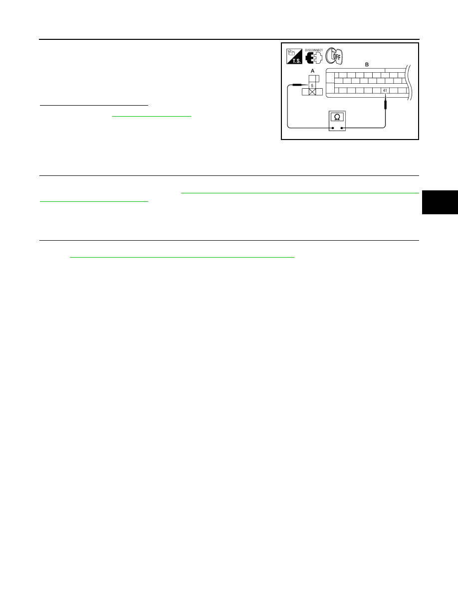
1. Disconnect stop lamp relay connector.
2. Check continuity between stop lamp relay connector E12 (A)
terminal 5 and ABS actuator and electric unit (control unit) con-
nector E127 (B) terminal 41.
Is the inspection result normal?
YES
>> Refer to
NO
>> Repair or replace malfunctioning components.
Special Repair Requirement
INFOID:0000000007818493
1.
ADJUSTMENT OF STEERING ANGLE SENSOR NEUTRAL POSITION
Always perform neutral position adjustment for the steering angle sensor when replacing the ABS actuator
and electric unit (control unit). Refer to
BRC-121, "ADJUSTMENT OF STEERING ANGLE SENSOR NEU-
>> GO TO 2
2.
CALIBRATION OF DECEL G SENSOR
Always perform calibration of decel G sensor when replacing the ABS actuator and electric unit (control unit).
BRC-122, "CALIBRATION OF DECEL G SENSOR : Description"
.
>> END
Continuity should exist.
AWFIA0479ZZ
August 2012
2012 Pathfinder
Нет комментариевНе стесняйтесь поделиться с нами вашим ценным мнением.
Текст