Nissan Pathfinder (2012 year). Instruction — part 517
SUSPENSION ARM
RSU-13
< REMOVAL AND INSTALLATION >
C
D
F
G
H
I
J
K
L
M
A
B
RSU
N
O
P
• Check the suspension arm for damage, cracks, deformation and
replace if necessary.
• Check the rubber bushing for damage, cracks and deformation.
Replace suspension arm assembly if necessary.
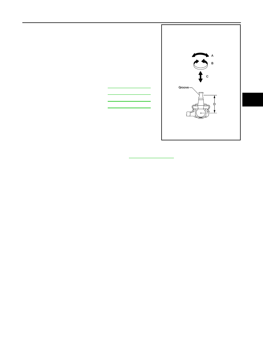
• Check the ball joint. Replace the suspension arm assembly if any
of the following exists:
- Ball stud is worn.
- Joint is hard to swing.
- Play in axial direction is excessive.
• Before checking, turn the ball joint at least 10 revolutions so that
the ball joint is properly broken in.
INSTALLATION
Installation is in the reverse order of removal.
• Tighten the nuts and bolts to specification. Refer to
• Perform final tightening of the nuts and bolts for the links (with rubber bushings) under unladen conditions
with the tires on level ground.
Swinging force (A)
.
Turning force (B)
: Refer to
.
Vertical end play (C)
: Refer to
.
Height (D)
.
WEIA0131E
August 2012
2012 Pathfinder
RSU-14
< REMOVAL AND INSTALLATION >
FRONT LOWER LINK
FRONT LOWER LINK
Removal and Installation
INFOID:0000000007357025
REMOVAL
1. Remove the wheel and tire assembly using power tool.
2. Remove the stabilizer bar. Refer to
RSU-18, "Removal and Installation"
.
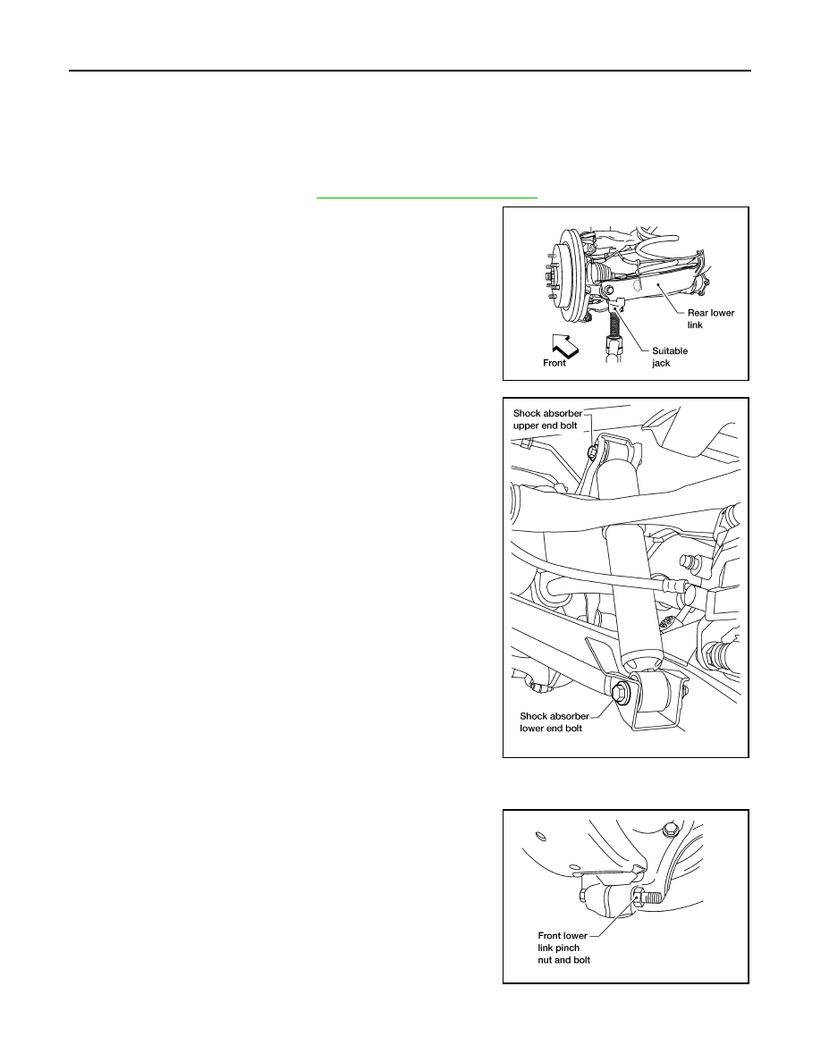
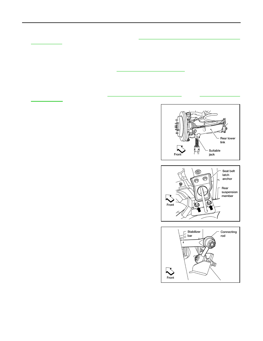
3. Set a suitable jack under the rear lower link to relieve the coil
spring tension.
NOTE:
LH side shown, RH side similar.
4. Remove the shock absorber lower end bolt.
NOTE:
LH side shown, RH side similar.
5. Remove the adjusting bolt and nut, and the bolt and nut, from the front lower link and rear suspension
member using power tool.
6. Remove the front lower link pinch bolt and nut on the knuckle
side using power tool.
NOTE:
LH side shown, RH side similar.
7. Disconnect the front lower link from the knuckle using a soft
hammer.
CAUTION:
Do not damage the ball joint with the soft hammer.
8. Remove the front lower link.
INSPECTION AFTER REMOVAL
• Check front lower link and bushing for any deformation, crack, or damage. Replace if necessary.
LEIA0077E
LEIA0110E
LEIA0086E
August 2012
2012 Pathfinder
FRONT LOWER LINK
RSU-15
< REMOVAL AND INSTALLATION >
C
D
F
G
H
I
J
K
L
M
A
B
RSU
N
O
P
• Check rubber bushing for damage, cracks and deformation. Replace suspension arm assembly if neces-
sary.
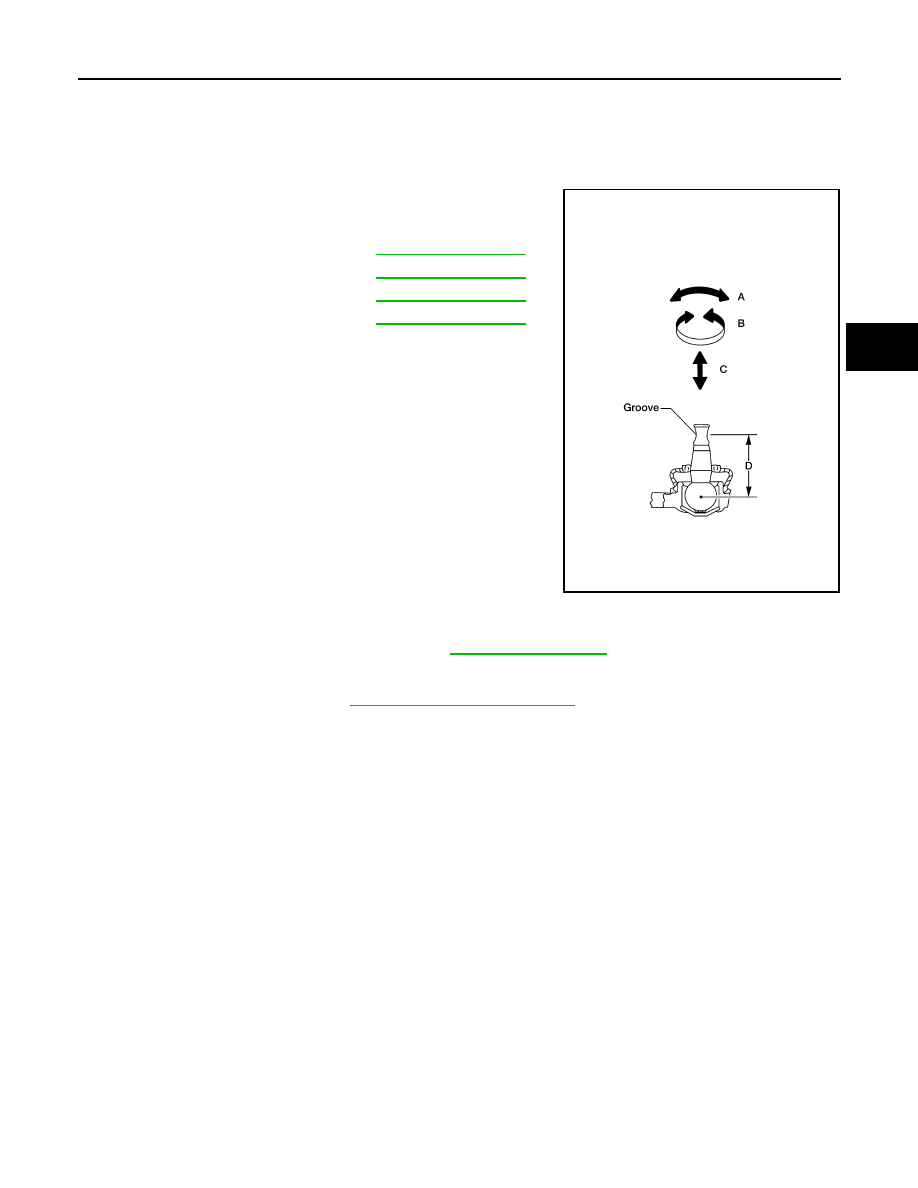
• Check ball joint. Replace suspension arm assembly if any of the following exists:
- Ball stud is worn.
- Joint is hard to swing.
- Play in axial direction is excessive.
• Before checking, turn ball joint at least 10 revolutions so that ball
joint is properly broken in.
INSTALLATION
Installation is in the reverse order of removal.
• Tighten the nuts and bolts to specification. Refer to
• Perform the final tightening of the front lower link nuts and bolts (with rubber bushings) under unladen condi-
tions with tires on level ground.
• Check the wheel alignment. Refer to
FSU-7, "Front Wheel Alignment"
.
Swinging force (A)
.
Turning force (B)
: Refer to
.
Vertical end play (C)
: Refer to
.
Height (D)
.
WEIA0131E
August 2012
2012 Pathfinder
RSU-16
< REMOVAL AND INSTALLATION >
REAR LOWER LINK & COIL SPRING
REAR LOWER LINK & COIL SPRING
Removal and Installation
INFOID:0000000007357026
REMOVAL
1. Remove the wheel and tire assembly using power tool. Refer to
2. If removing the LH rear lower link and coil spring, remove the spare wheel and tire assembly.
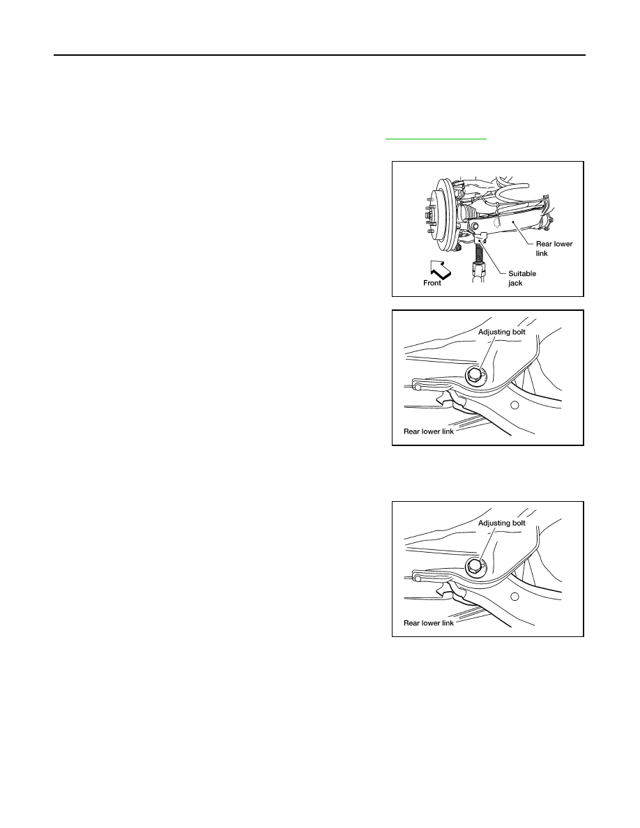
3. Set a suitable jack to relieve the coil spring tension and support
the rear lower link.
4. Loosen the rear lower link adjusting bolt and nut connected to
the rear suspension member without removing the adjusting bolt
and nut, using power tool.
5. Remove the rear lower link pinch bolt and nut from the knuckle using power tool.
6. Slowly lower the rear lower link using the suitable jack to release the coil spring tension. Then remove the
upper rubber seat, coil spring and lower rubber seat from the rear lower link.
7. Remove the rear lower link adjusting bolt and nut from the rear
suspension member using power tool, then remove the rear
lower link.
INSPECTION AFTER REMOVAL
Check for deformation, cracks, or other damage and replace if necessary.
INSTALLATION
Installation is in the reverse order of removal.
LEIA0077E
LEIA0009E
LEIA0009E
August 2012
2012 Pathfinder
REAR LOWER LINK & COIL SPRING
RSU-17
< REMOVAL AND INSTALLATION >
C
D
F
G
H
I
J
K
L
M
A
B
RSU
N
O
P
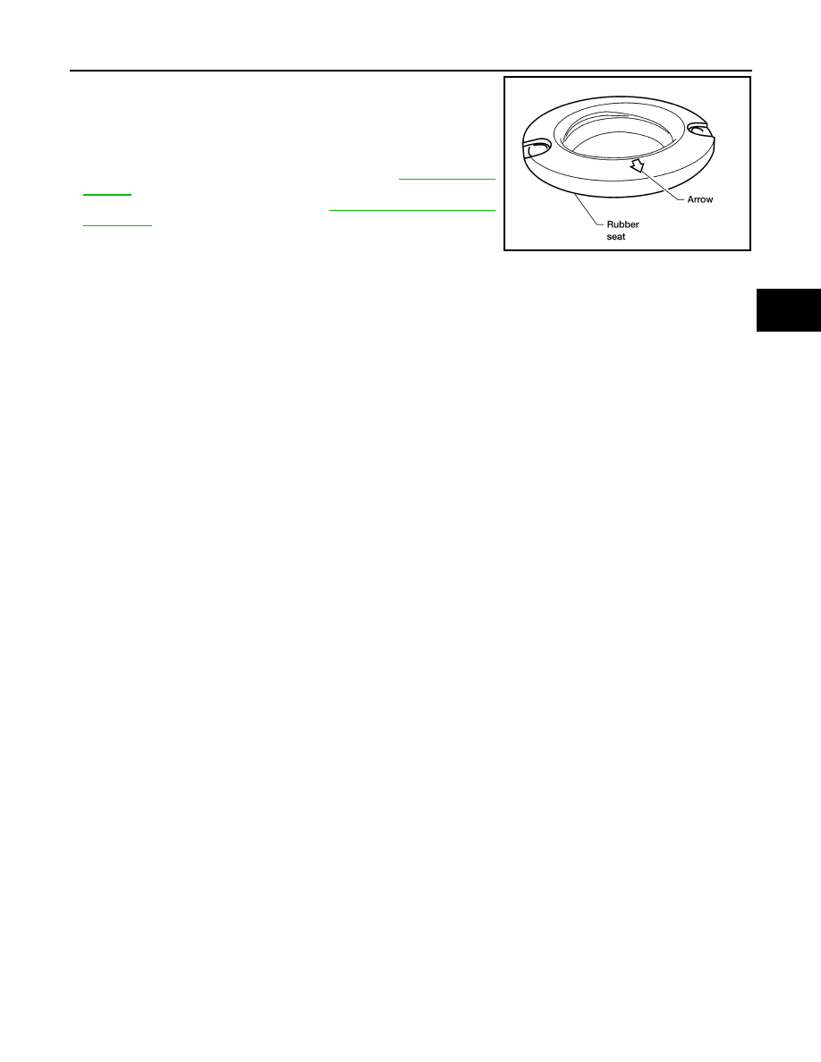
• When installing the upper and lower rubber seats for the rear coil
springs, the arrow embossed on the rubber seats must point out
toward the wheel and tire assembly.
• Perform the final tightening of the rear lower link nuts and bolts
(with rubber bushings) under unladen conditions with tires on level
ground.
• Tighten the nuts and bolts to specification. Refer to
• Check the wheel alignment. Refer to
.
LEIA0076E
August 2012
2012 Pathfinder
RSU-18
< REMOVAL AND INSTALLATION >
STABILIZER BAR
STABILIZER BAR
Removal and Installation
INFOID:0000000007357027
REMOVAL
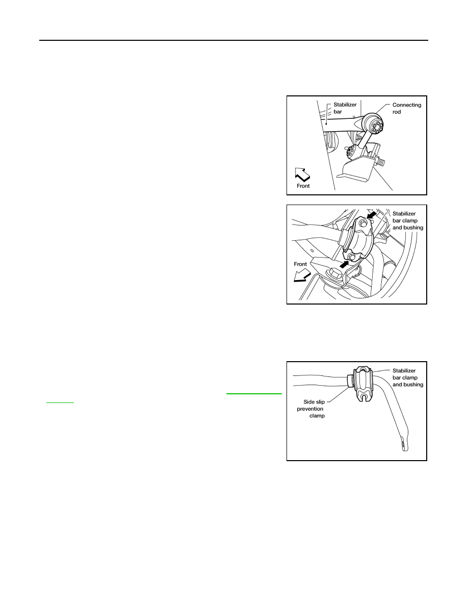
1. Disconnect the stabilizer bar ends from the connecting rods
using power tool.
2. Remove the stabilizer bar clamps using power tool, and remove
the stabilizer bar bushings.
3. Remove the stabilizer bar.
INSPECTION AFTER REMOVAL
• Check stabilizer bar for any deformation, cracks, or damage and replace if necessary.
• Check rubber bushings for deterioration, or cracks and replace if necessary.
INSTALLATION
Installation is in the reverse order of removal.
• Install the stabilizer bar bushings and clamps so they are posi-
tioned outside of the sideslip prevention clamp on the stabilizer
bar.
• Tighten the nuts and bolts to specification. Refer to
LEIA0111E
LEIA0113E
LEIA0112E
August 2012
2012 Pathfinder
REAR SUSPENSION MEMBER
RSU-19
< UNIT REMOVAL AND INSTALLATION >
C
D
F
G
H
I
J
K
L
M
A
B
RSU
N
O
P
UNIT REMOVAL AND INSTALLATION
REAR SUSPENSION MEMBER
Removal and Installation
INFOID:0000000007357028
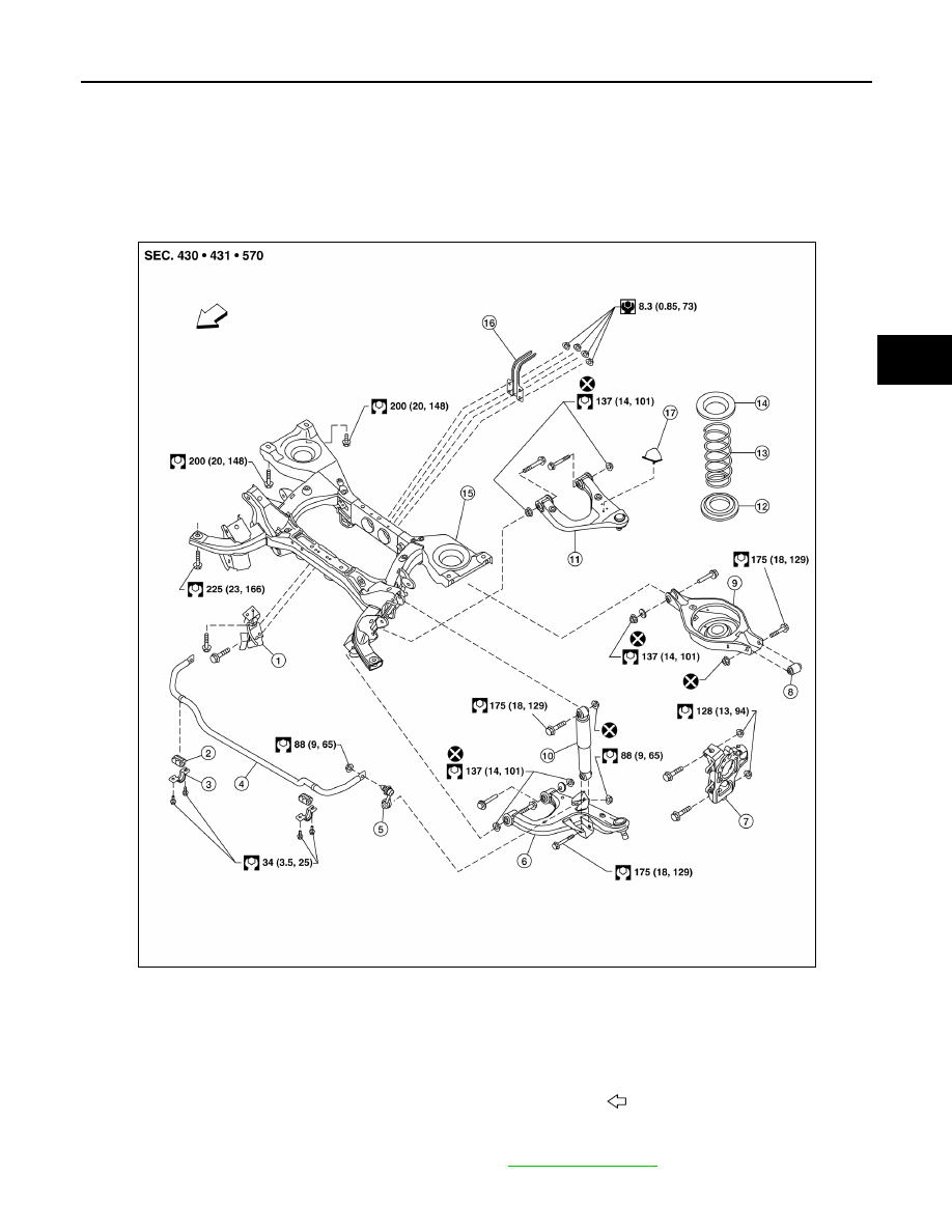
COMPONENTS
REMOVAL
1. Remove both rear wheel and tire assemblies. Refer to
.
1.
Seat belt latch anchor
2.
Stabilizer bar bushing
3.
Stabilizer bar clamp
4.
Stabilizer bar
5.
Connecting rod
6.
Front lower link
7.
Knuckle
8.
Bushing
9.
Rear lower link
10. Shock absorber
11. Suspension arm
12. Lower rubber seat
13. Coil spring
14. Upper rubber seat
15. Rear suspension member
16. Spare tire bracket
17. Bound bumper
Front
AWEIA0208GB
August 2012
2012 Pathfinder
RSU-20
< UNIT REMOVAL AND INSTALLATION >
REAR SUSPENSION MEMBER
2. Remove the spare tire.
3. Remove the brake caliper without disconnecting the brake hoses, using power tool. Reposition the brake
caliper out of the way using a suitable wire. Refer to
BR-47, "Removal and Installation of Brake Caliper
.
CAUTION:
• Do not crimp or stretch the brake hose when repositioning the brake caliper out of the way.
• Do not press the brake pedal while the brake caliper is positioned out of the way.
4. Remove the two rear brake rotors.
5. Remove the two rear drive shafts. Refer to
RAX-8, "Removal and Installation"
6. Disconnect the parking brake cables brackets from the rear suspension member.
7. Disconnect the two rear wheel sensor connectors and harness clips.
8. Remove the rear final drive vent tube from the rear suspension member and frame.
9. Remove the rear final drive. Refer to
DLN-426, "Removal and Installation"
10. Set a suitable jack to support each of the rear lower links and the
coil spring tension.
11. Remove both of the rear lower link outer bolts using power tool,
and lower the jack to remove the rear coil springs, and the upper
and lower rubber seats.
12. Remove the two bolts to disconnect the seat belt latch anchor
from the rear suspension member using power tool.
13. Disconnect both of the connecting rods from the rear stabilizer
bar.
LEIA0077E
LEIA0109E
LEIA0111E
August 2012
2012 Pathfinder
Нет комментариевНе стесняйтесь поделиться с нами вашим ценным мнением.
Текст