Nissan Pathfinder (2012 year). Instruction — part 304
AUTOMATIC SPEED CONTROL DEVICE (ASCD)
EC-513
< SYSTEM DESCRIPTION >
[VK56DE]
C
D
E
F
G
H
I
J
K
L
M
A
EC
N
P
O
When the RESUME/ACCELERATE switch is pressed after canceling operation other than pressing MAIN
switch, vehicle speed will return to last set speed. To resume vehicle set speed, vehicle condition must meet
following conditions.
• Brake pedal is released
• A/T selector lever position is other than P and N
• Vehicle speed is greater than 40 km/h (25 MPH) and less than 144 km/h (89 MPH)
Component Description
INFOID:0000000007358430
ASCD STEERING SWITCH
EC-873, "Component Description"
ASCD BRAKE SWITCH
EC-877, "Component Description"
STOP LAMP SWITCH
ELECTRIC THROTTLE CONTROL ACTUATOR
ASCD INDICATOR
EC-920, "Component Description"
August 2012
2012 Pathfinder
EC-514
< SYSTEM DESCRIPTION >
[VK56DE]
CAN COMMUNICATION
CAN COMMUNICATION
System Description
INFOID:0000000007358431
CAN (Controller Area Network) is a serial communication line for real time application. It is an on-vehicle mul-
tiplex communication line with high data communication speed and excellent error detection ability. Many elec-
tronic control units are equipped onto a vehicle, and each control unit shares information and links with other
control units during operation (not independent). In CAN communication, control units are connected with 2
communication lines (CAN H line, CAN L line) allowing a high rate of information transmission with less wiring.
Each control unit transmits/receives data but selectively reads required data only.
LAN-53, "CAN Communication Signal Chart"
, about CAN communication for detail.
August 2012
2012 Pathfinder
COOLING FAN CONTROL
EC-515
< SYSTEM DESCRIPTION >
[VK56DE]
C
D
E
F
G
H
I
J
K
L
M
A
EC
N
P
O
COOLING FAN CONTROL
Description
INFOID:0000000007358432
SYSTEM DESCRIPTION
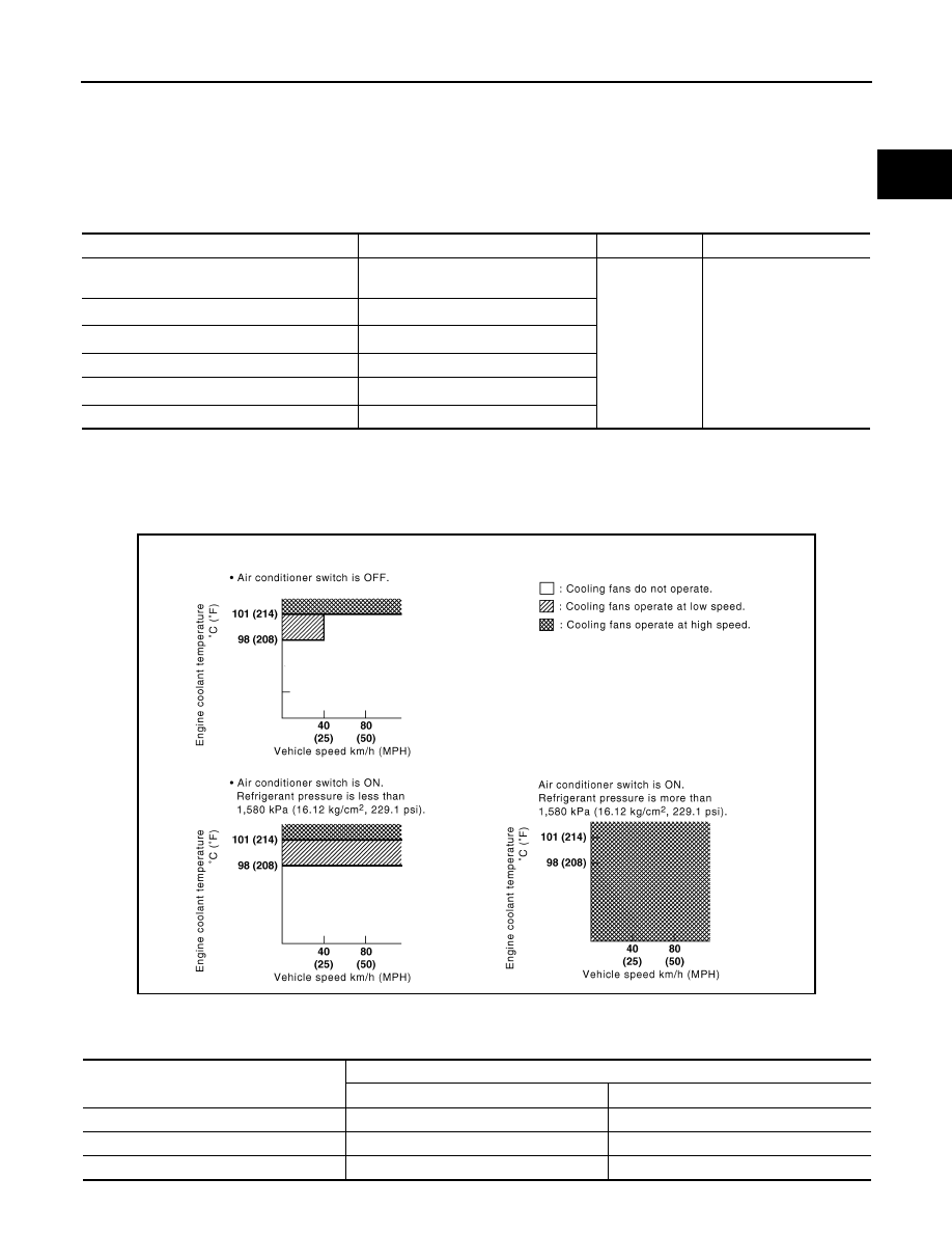
Cooling Fan Control
*1: The ECM determines the start signal status by the signals of engine speed and battery voltage.
*2: This signal is sent to ECM via the CAN communication line.
The ECM controls the cooling fan speed corresponding to the vehicle speed, engine coolant temperature,
refrigerant pressure and air conditioner ON signal. The control system has a 3-step control [HIGH/LOW/OFF].
Cooling Fan Operation
Cooling Fan Relay Operation
The ECM controls cooling fan relays in the IPDM E/R via the CAN communication line.
Sensor
Input Signal to ECM
ECM function
Actuator
Crankshaft position sensor (POS)
Camshaft position sensor (PHASE)
Engine speed*
1
Cooling fan
control
IPDM E/R
(Cooling fan relays)
Battery
Battery voltage*
1
Unified meter control unit
Vehicle speed*
2
Engine coolant temperature sensor
Engine coolant temperature
Air conditioner switch
Air conditioner ON signal*
2
Refrigerant pressure sensor
Refrigerant pressure
JMBIA0700GB
Cooling fan speed
Cooling fan relay
LO
HI
Stop (OFF)
OFF
OFF
Low (LOW)
ON
OFF
High (HI)
ON
ON
August 2012
2012 Pathfinder
EC-516
< SYSTEM DESCRIPTION >
[VK56DE]
EVAPORATIVE EMISSION SYSTEM
EVAPORATIVE EMISSION SYSTEM
Description
INFOID:0000000007358433
SYSTEM DESCRIPTION
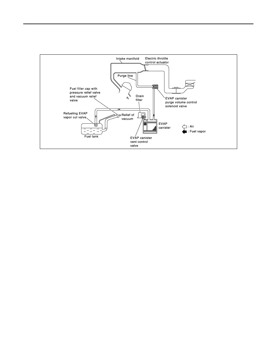
The evaporative emission system is used to reduce hydrocarbons emitted into the atmosphere from the fuel
system. This reduction of hydrocarbons is accomplished by activated charcoals in the EVAP canister.
The fuel vapor in the sealed fuel tank is led into the EVAP canister which contains activated carbon and the
vapor is stored there when the engine is not operating or when refueling to the fuel tank.
The vapor in the EVAP canister is purged by the air through the purge line to the intake manifold when the
engine is operating. EVAP canister purge volume control solenoid valve is controlled by ECM. When the
engine operates, the flow rate of vapor controlled by EVAP canister purge volume control solenoid valve is
proportionally regulated as the air flow increases.
EVAP canister purge volume control solenoid valve also shuts off the vapor purge line during decelerating and
idling.
PBIB3639E
August 2012
2012 Pathfinder
EVAPORATIVE EMISSION SYSTEM
EC-517
< SYSTEM DESCRIPTION >
[VK56DE]
C
D
E
F
G
H
I
J
K
L
M
A
EC
N
P
O
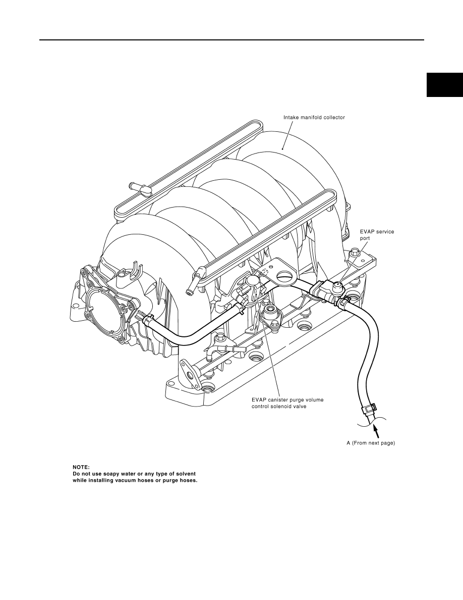
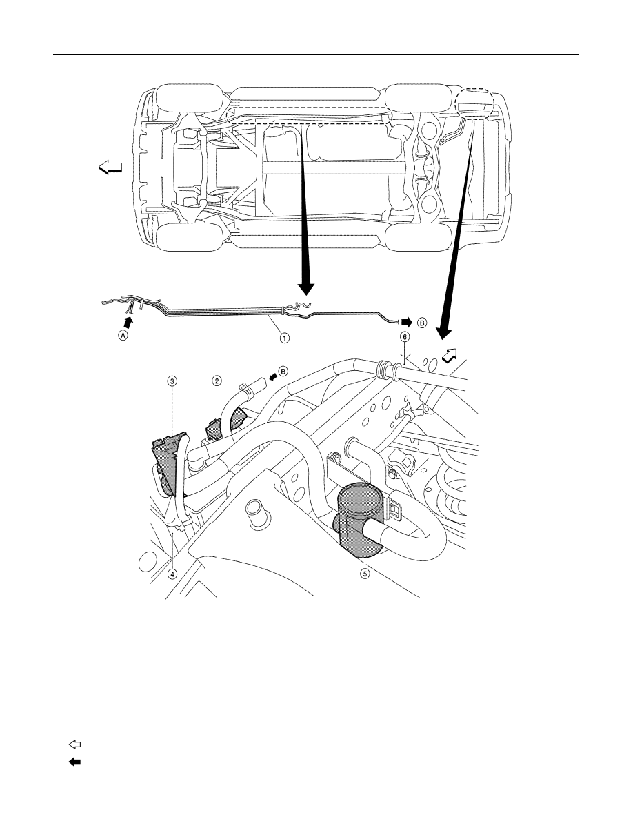
EVAPORATIVE EMISSION LINE DRAWING
PBIB2053E
August 2012
2012 Pathfinder
EC-518
< SYSTEM DESCRIPTION >
[VK56DE]
EVAPORATIVE EMISSION SYSTEM
1.
EVAP vapor purge line
2.
EVAP control system pressure sen-
sor
3.
EVAP canister vent control valve
4.
EVAP canister
5.
Drain filter
6.
Fuel filler pipe
: Vehicle front
: Previous figure
ALBIA0366ZZ
August 2012
2012 Pathfinder
INTAKE VALVE TIMING CONTROL
EC-519
< SYSTEM DESCRIPTION >
[VK56DE]
C
D
E
F
G
H
I
J
K
L
M
A
EC
N
P
O
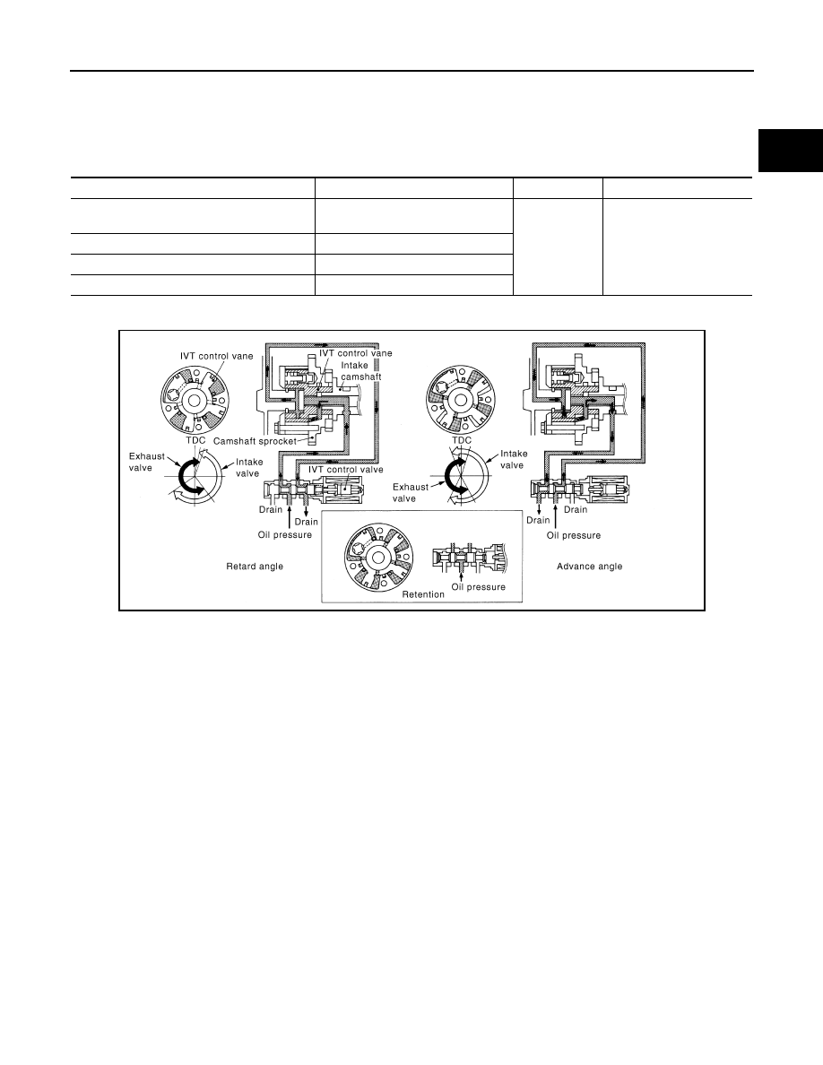
INTAKE VALVE TIMING CONTROL
Description
INFOID:0000000007358434
SYSTEM DESCRIPTION
*: This signal is sent to the ECM via the CAN communication line
This mechanism hydraulically controls cam phases continuously with the fixed operating angle of the intake
valve.
The ECM receives signals such as crankshaft position, camshaft position, engine speed and engine coolant
temperature. Then, the ECM sends ON/OFF pulse duty signals to the intake valve timing (IVT) control sole-
noid valve depending on driving status. This makes it possible to control the shut/open timing of the intake
valve to increase engine torque in low/mid speed range and output in high-speed range.
Sensor
Input signal to ECM
ECM function
Actuator
Crankshaft position sensor (POS)
Camshaft position sensor (PHASE)
Engine speed
Intake valve
timing control
Intake valve timing control
solenoid valve
Intake valve timing control position sensor
Intake valve timing signal
Engine coolant temperature sensor
Engine coolant temperature
Unified meter control unit
Vehicle speed*
PBIB3276E
August 2012
2012 Pathfinder
EC-520
< SYSTEM DESCRIPTION >
[VK56DE]
FUEL FILLER CAP WARNING SYSTEM
FUEL FILLER CAP WARNING SYSTEM
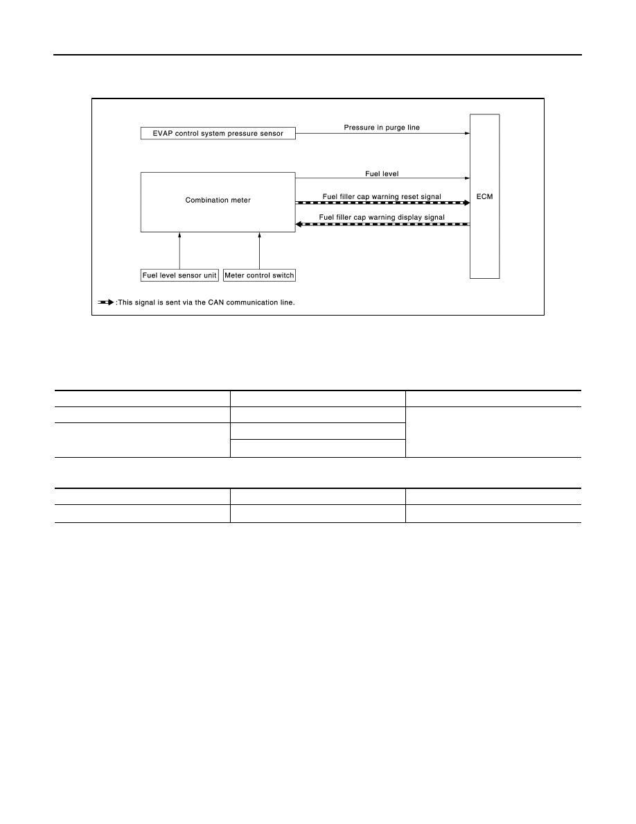
System Diagram
INFOID:0000000007358435
System Description
INFOID:0000000007358436
INPUT/OUTPUT SIGNAL CHART
Input
*: This signal is sent to the ECM via the CAN communication line.
Output
*: This signal is sent to the combination meter via the CAN communication line.
SYSTEM DESCRIPTION
The fuel filler cap warning system alerts the driver to the prevention of the fuel filler being left uncapped and
malfunction occurrences after refueling, by turning ON the fuel filler cap warning display on the combination
meter.
ECM judges a refueled state, based on a fuel level signal transmitted from the combination meter.
When a very small leak is detected through the EVAP leak diagnosis performed after judging the refueled
state, ECM transmits a fuel filler cap warning display signal (request for display ON) to the combination meter
via CAN communication.
When receiving the signal, the combination meter turns ON the fuel filler cap warning display.
CAUTION:
Check fuel filler cap installation condition when the fuel filler cap warning display turns ON.
Reset Operation
The fuel filler cap warning lamp tunes OFF, according to any condition listed below:
• Reset operation is performed by operating the meter control switch on the combination meter.
- When the reset operation is performed, the combination meter transmits a fuel filler cap warning reset signal
to ECM via CAN communication. ECM transmits a fuel filler cap warning display signal (request for display
OFF) to the combination meter via CAN communication. When receiving the signal, the combination meter
turns OFF the fuel filler cap warning display.
• EVAP leak diagnosis result is normal.
• Fuel refilled.
Unit/Sensor
Input signal to ECM
ECM function
EVAP control system pressure sensor
Pressure in purge line
Fuel filler cap warning control
Combination meter
Fuel level
Fuel filler cap warning reset signal
*
JSBIA0797GB
Unit
Output signal
Actuator
ECM
Fuel filler cap warning display signal
*
Combination meter
August 2012
2012 Pathfinder
Нет комментариевНе стесняйтесь поделиться с нами вашим ценным мнением.
Текст