Nissan Pathfinder (2012 year). Instruction — part 399
CONSULT CHECKING SYSTEM
GI-45
< BASIC INSPECTION >
C
D
E
F
G
H
I
J
K
L
M
B
GI
N
O
P
CONSULT CHECKING SYSTEM
Description
INFOID:0000000007359095
NOTE:
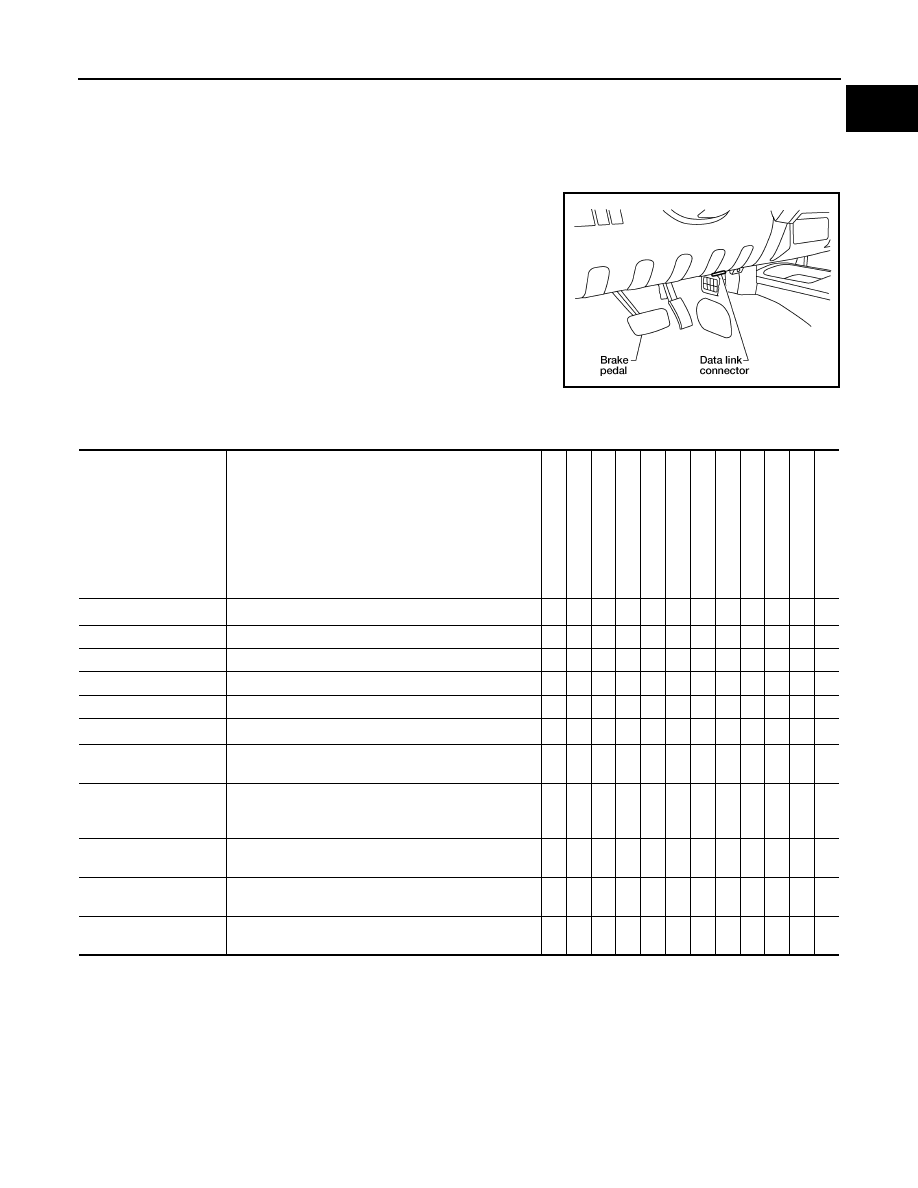
This vehicle is diagnosed using CONSULT-III plus.
• When CONSULT is connected with a data link connector equipped
on the vehicle side, it will communicate with the control unit
equipped in the vehicle and then enable various kinds of diagnos-
tic tests.
• Refer to CONSULT-III plus Operation Instruction for more information.
Function and System Application
INFOID:0000000007359096
x : Applicable
1: With 4WD
2: With Intelligent Key
3: Except base audio
4: With color display
5: With automatic drive positioner
6: With ATX14B transfer case
BBIA0538E
Direct Diagnostic Mode
Description
ALL MODE
A
W
D/4W
D
1
ABS
INTELLI
G
ENT
KEY
2
IP
DM E/
R
MUL
T
I A
V
3
HV
AC
4
BCM
TRANSMISSION
AIR BAG
AUT
O
DRIVE
POS.
5
METER/M
&
A
ENGINE
ECU identification
The ECU part number is displayed.
x
6
x
x
-
x
x
x
x
x
x
-
x
Self Diagnostic Result
The ECU self diagnostic results are displayed.
x
x
x
x
x
x
x
x
x
x
x
x
Data Monitor
The ECU input/output data is displayed in real time.
x
x
x
x
x
x
x
x
x
x
x
x
Active Test
The ECU activates outputs to test components.
-
x
x
x
-
-
x
-
-
x
-
x
Cause of Warning Lamp States the reason the air bag warning lamp is ON.
-
-
-
-
-
-
-
-
x
-
-
-
Work support
The settings for ECU functions can be changed.
x
6
x
x
-
-
-
x
-
-
x
-
x
DTC Work Support
The status of system monitoring tests and the self di-
agnosis status/results can be confirmed.
-
-
-
-
-
-
-
x
-
-
-
x
Configuration
• The vehicle specification can be read and saved.
• The vehicle specification can be written when re-
placing ECU.
-
-
-
-
-
-
x
-
-
-
-
-
TROUBLE DIAG
RECORD
Self diagnostic history and trouble diagnosis records in
ECU are displayed.
-
-
-
-
-
-
-
-
x
-
-
-
CAN Diagnosis
This mode displays network diagnostic results of CAN
communication using a diagram.
x
x
x
x
x
x
x
x
x
x
x
x
CAN Diag Support Mntr
The result of transmit/receive diagnosis of CAN com-
munication is displayed.
x
x
x
x
x
x
x
x
-
x
x
x
August 2012
2012 Pathfinder

GI-46
< BASIC INSPECTION >
CONSULT CHECKING SYSTEM
CONSULT Data Link Connector (DLC) Circuit
INFOID:0000000007359097
INSPECTION PROCEDURE
If the CONSULT cannot diagnose the system properly, check the following items.
NOTE:
The CAN and DDL2 circuits from DLC pins 6, 7 and 14 may be connected to more than one system. A short in
any circuit connected to a control unit in one system may affect CONSULT access to other systems.
Symptom
Check item
CONSULT cannot access any
system.
• CONSULT DLC power supply circuit (Terminal 8) and ground circuit (Terminal 4)
CONSULT cannot access indi-
vidual system. (Other systems
can be accessed.)
• Power supply and ground circuit for the control unit of the system (For detailed circuit, refer to wiring
diagram for each system.)
• Open or short circuit between the system and CONSULT DLC (For detailed circuit, refer to wiring
diagram for each system.)
• Open or short circuit CAN communication line. Refer to
LAN-14, "Trouble Diagnosis Flow Chart"
.
August 2012
2012 Pathfinder
CONSULT CHECKING SYSTEM
GI-47
< WIRING DIAGRAM >
C
D
E
F
G
H
I
J
K
L
M
B
GI
N
O
P
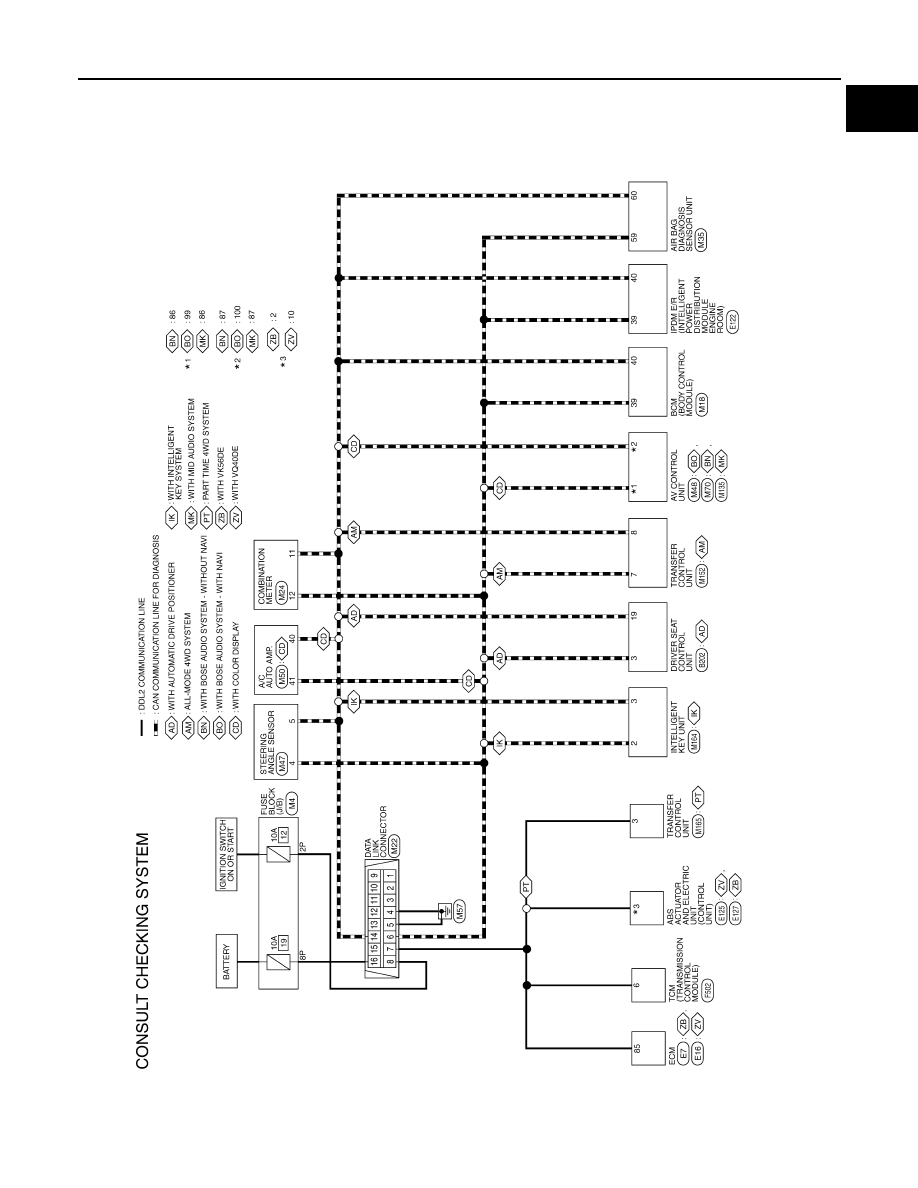
WIRING DIAGRAM
CONSULT CHECKING SYSTEM
Wiring Diagram
INFOID:0000000007359098
ABAWA0096GB
August 2012
2012 Pathfinder
GW-1
BODY EXTERIOR, DOORS, ROOF & VEHICLE SECURITY
C
D
E
F
G
H
I
J
L
M
SECTION
GW
A
B
GW
N
O
P
CONTENTS
GLASS & WINDOW SYSTEM
PRECAUTION . . . . . . . . . . . ...
PRECAUTIONS . . . . . . . . . . . . ...
Precaution Necessary for Steering Wheel Rota-
tion After Battery Disconnect . . . . . . . . .....
Handling for Adhesive and Primer . . . . . . ....
Precaution for Procedure without Cowl Top Cover . ..
PREPARATION . . . . . . . . . . .
PREPARATION . . . . . . . . . . . . ...
Special Service Tool . . . . . . . . . . . .....
Commercial Service Tool . . . . . . . . . . ..
SYMPTOM DIAGNOSIS . . . . . . . ...
SQUEAK AND RATTLE TROUBLE DIAG-
NOSES . . . . . . . . . . . . . . . .
Work Flow . . . . . . . . . . . . . . . .....
Generic Squeak and Rattle Troubleshooting . . ....
Diagnostic Worksheet . . . . . . . . . . . ...
UNIT REMOVAL AND INSTALLATION . ..
WINDSHIELD GLASS . . . . . . . . . ...
Removal and Installation . . . . . . . . . . .
FRONT DOOR GLASS AND REGULATOR . .
Front Door Glass . . . . . . . . . . . . . .
Front Door Glass Regulator . . . . . . . . . .
REAR DOOR GLASS AND REGULATOR . ...
Rear Door Glass . . . . . . . . . . . . . ..
Rear Door Glass Regulator . . . . . . . . . .
SIDE WINDOW GLASS . . . . . . . . .
Removal and Installation . . . . . . . . . . .
GLASS HATCH . . . . . . . . . . . . .
Removal and Installation . . . . . . . . . . .
Rear Window Stay Disposal . . . . . . . . .
August 2012
2012 Pathfinder
GW-2
< PRECAUTION >
PRECAUTIONS
PRECAUTION
PRECAUTIONS
Precaution for Supplemental Restraint System (SRS) "AIR BAG" and "SEAT BELT
PRE-TENSIONER"
INFOID:0000000007355826
The Supplemental Restraint System such as “AIR BAG” and “SEAT BELT PRE-TENSIONER”, used along
with a front seat belt, helps to reduce the risk or severity of injury to the driver and front passenger for certain
types of collision. This system includes seat belt switch inputs and dual stage front air bag modules. The SRS
system uses the seat belt switches to determine the front air bag deployment, and may only deploy one front
air bag, depending on the severity of a collision and whether the front occupants are belted or unbelted.
Information necessary to service the system safely is included in the SR and SB section of this Service Man-
ual.
WARNING:
• To avoid rendering the SRS inoperative, which could increase the risk of personal injury or death in
the event of a collision which would result in air bag inflation, all maintenance must be performed by
an authorized NISSAN/INFINITI dealer.
• Improper maintenance, including incorrect removal and installation of the SRS, can lead to personal
injury caused by unintentional activation of the system. For removal of Spiral Cable and Air Bag
Module, see the SR section.
• Do not use electrical test equipment on any circuit related to the SRS unless instructed to in this
Service Instruction. SRS wiring harnesses can be identified by yellow and/or orange harnesses or har-
ness connectors.
PRECAUTIONS WHEN USING POWER TOOLS (AIR OR ELECTRIC) AND HAMMERS
WARNING:
• When working near the Airbag Diagnosis Sensor Unit or other Airbag System sensors with the Igni-
tion ON or engine running, DO NOT use air or electric power tools or strike near the sensor(s) with a
hammer. Heavy vibration could activate the sensor(s) and deploy the air bag(s), possibly causing
serious injury.
• When using air or electric power tools or hammers, always switch the Ignition OFF, disconnect the
battery, and wait at least 3 minutes before performing any service.
Precaution Necessary for Steering Wheel Rotation After Battery Disconnect
INFOID:0000000007355827
NOTE:
• This Procedure is applied only to models with Intelligent Key system and NATS (NISSAN ANTI-THEFT SYS-
TEM).
• Remove and install all control units after disconnecting both battery cables with the ignition knob in the
″
LOCK
″
position.
• Always use CONSULT to perform self-diagnosis as a part of each function inspection after finishing work. If
DTC is detected, perform trouble diagnosis according to self-diagnostic results.
For models equipped with the Intelligent Key system and NATS, an electrically controlled steering lock mech-
anism is adopted on the key cylinder.
For this reason, if the battery is disconnected or if the battery is discharged, the steering wheel will lock and
steering wheel rotation will become impossible.
If steering wheel rotation is required when battery power is interrupted, follow the procedure below before
starting the repair operation.
OPERATION PROCEDURE
1. Connect both battery cables.
NOTE:
Supply power using jumper cables if battery is discharged.
2. Use the Intelligent Key or mechanical key to turn the ignition switch to the
″
ACC
″
position. At this time, the
steering lock will be released.
3. Disconnect both battery cables. The steering lock will remain released and the steering wheel can be
rotated.
4. Perform the necessary repair operation.
August 2012
2012 Pathfinder
PRECAUTIONS
GW-3
< PRECAUTION >
C
D
E
F
G
H
I
J
L
M
A
B
GW
N
O
P
5. When the repair work is completed, return the ignition switch to the
″
LOCK
″
position before connecting
the battery cables. (At this time, the steering lock mechanism will engage.)
6. Perform a self-diagnosis check of all control units using CONSULT.
Handling for Adhesive and Primer
INFOID:0000000007355828
• Do not use an adhesive which is past its usable date. Shelf life of this product is limited to six months after
the date of manufacture. Carefully adhere to the expiration or manufacture date printed on the box.
• Keep primers and adhesive in a cool, dry place. Ideally, they should be stored in a refrigerator.
• Open the seal of the primer and adhesive just before application. Discard the remainder.
• Before application, be sure to shake the primer container to stir the contents. If any floating material is found,
do not use it.
• If any primer or adhesive contacts the skin, wipe it off with gasoline or equivalent and wash the skin with
soap.
• When using primer and adhesive, always observe the precautions in the instruction instruction.
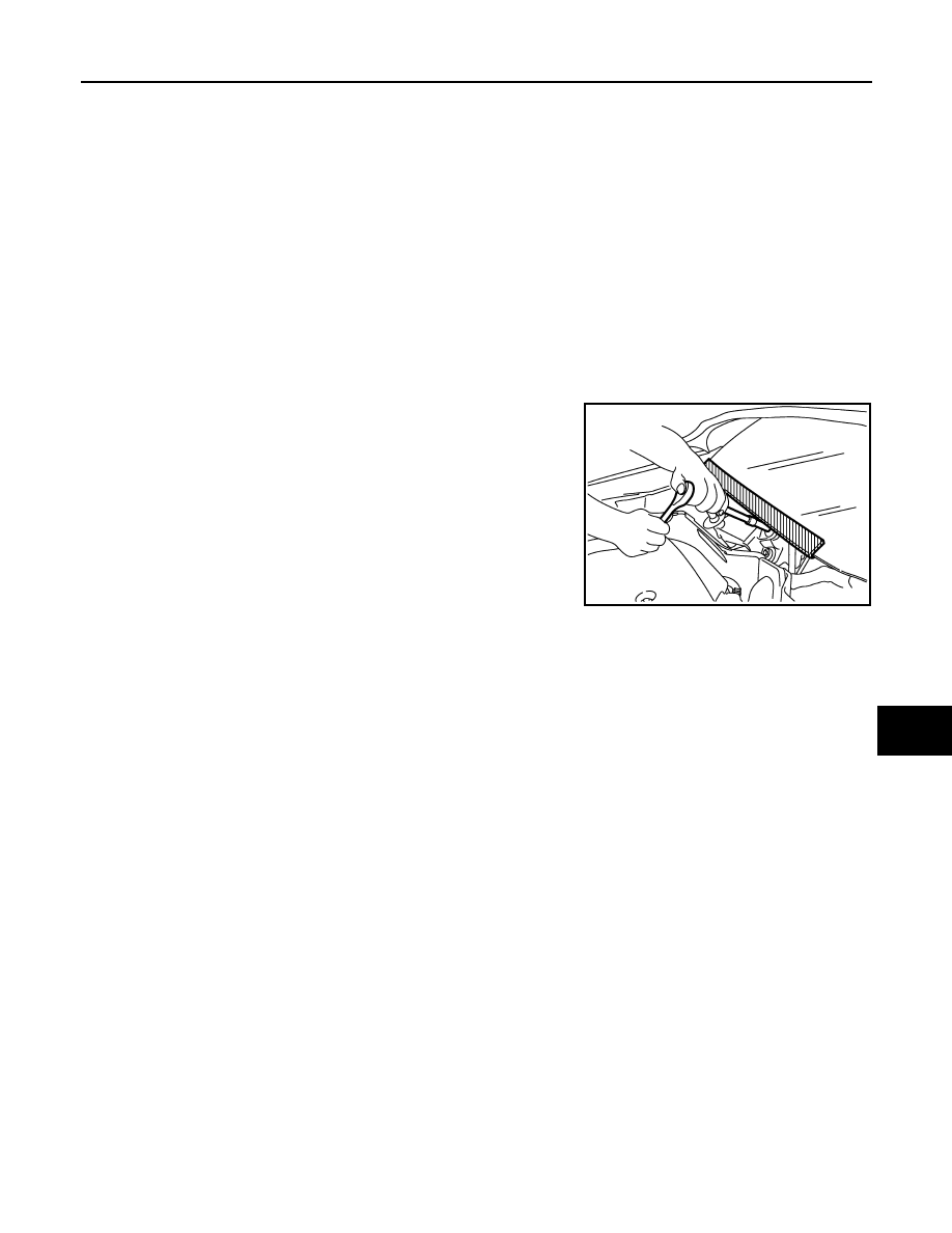
Precaution for Procedure without Cowl Top Cover
INFOID:0000000007355829
When performing the procedure after removing cowl top cover, cover
the lower end of windshield with urethane, etc.
PIIB3706J
August 2012
2012 Pathfinder
GW-4
< PREPARATION >
PREPARATION
PREPARATION
PREPARATION
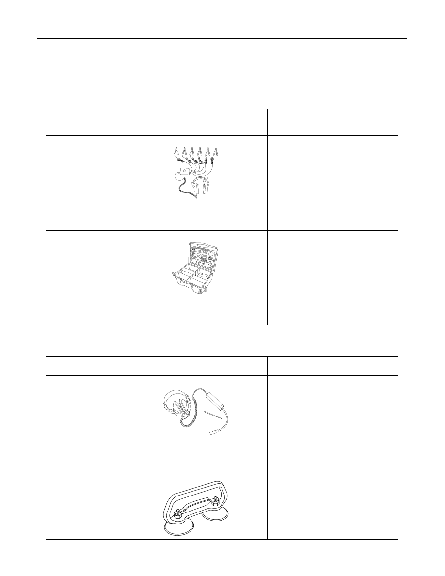
Special Service Tool
INFOID:0000000007355830
The actual shapes of Kent-Moore tools may differ from those of special service tools illustrated here.
Commercial Service Tool
INFOID:0000000007355831
Tool number
(Kent-Moore No.)
Tool name
Description
—
(J-39570)
Chassis ear
Locating the noise
—
(J-43980)
NISSAN Squeak and Rat-
tle Kit
Repairing the cause of noise
SIIA0993E
SIIA0994E
(Kent-Moore No.)
Tool name
Description
(J-39565)
Engine ear
Locating the noise
(
—
)
Suction Lifter
Holding door glass
SIIA0995E
LIIA1991E
August 2012
2012 Pathfinder
SQUEAK AND RATTLE TROUBLE DIAGNOSES
GW-5
< SYMPTOM DIAGNOSIS >
C
D
E
F
G
H
I
J
L
M
A
B
GW
N
O
P
SYMPTOM DIAGNOSIS
SQUEAK AND RATTLE TROUBLE DIAGNOSES
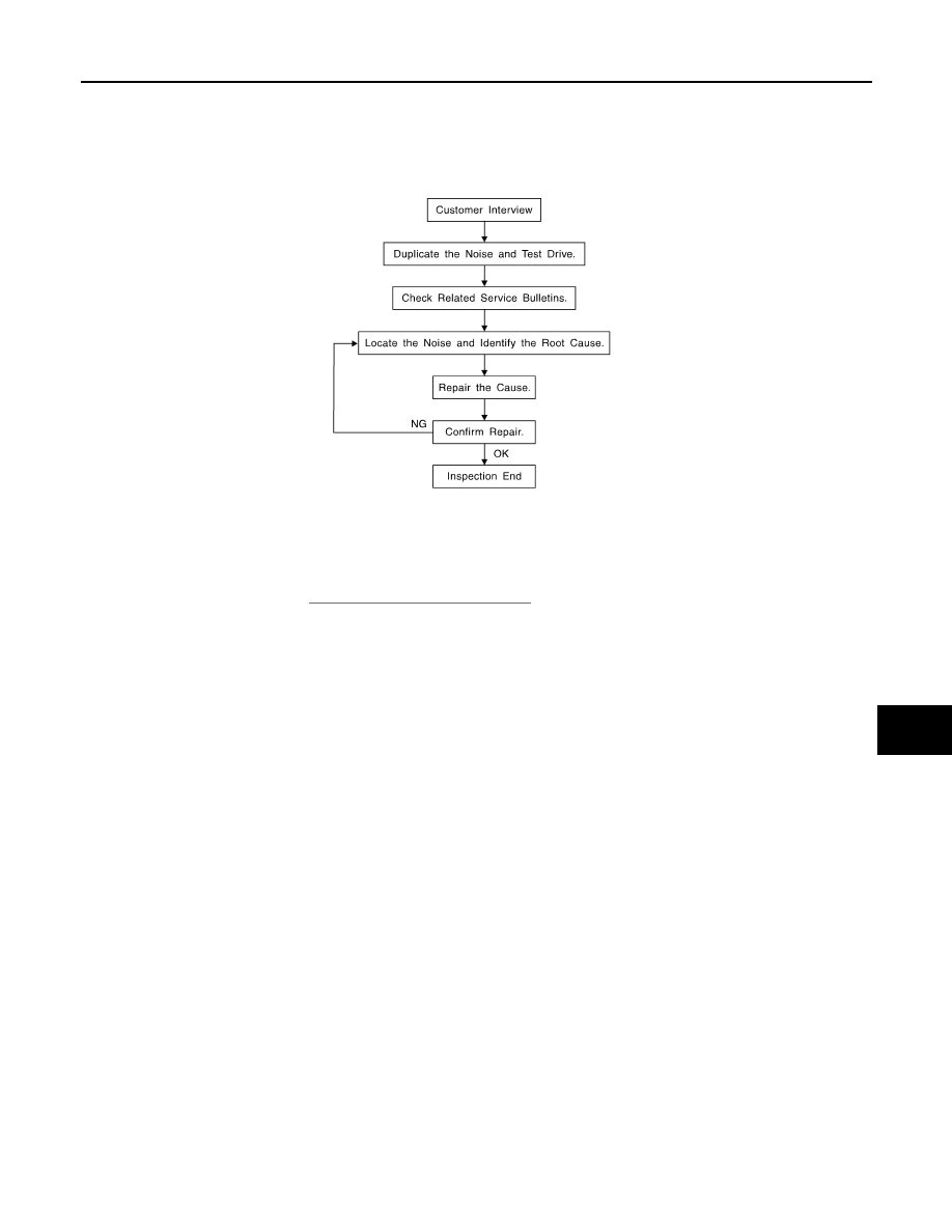
Work Flow
INFOID:0000000007355832
CUSTOMER INTERVIEW
Interview the customer if possible, to determine the conditions that exist when the noise occurs. Use the Diag-
nostic Worksheet during the interview to document the facts and conditions when the noise occurs and any
customer's comments; refer to
. This information is necessary to duplicate the
conditions that exist when the noise occurs.
• The customer may not be able to provide a detailed description or the location of the noise. Attempt to obtain
all the facts and conditions that exist when the noise occurs (or does not occur).
• If there is more than one noise in the vehicle, be sure to diagnose and repair the noise that the customer is
concerned about. This can be accomplished by test driving the vehicle with the customer.
• After identifying the type of noise, isolate the noise in terms of its characteristics. The noise characteristics
are provided so the customer, service adviser and technician are all speaking the same language when
defining the noise.
• Squeak —(Like tennis shoes on a clean floor)
Squeak characteristics include the light contact/fast movement/brought on by road conditions/hard surfaces
= higher pitch noise/softer surfaces = lower pitch noises/edge to surface = chirping.
• Creak—(Like walking on an old wooden floor)
Creak characteristics include firm contact/slow movement/twisting with a rotational movement/pitch depen-
dent on materials/often brought on by activity.
• Rattle—(Like shaking a baby rattle)
Rattle characteristics include the fast repeated contact/vibration or similar movement/loose parts/missing
clip or fastener/incorrect clearance.
• Knock —(Like a knock on a door)
Knock characteristics include hollow sounding/sometimes repeating/often brought on by driver action.
• Tick—(Like a clock second hand)
Tick characteristics include gentle contacting of light materials/loose components/can be caused by driver
action or road conditions.
• Thump—(Heavy, muffled knock noise)
Thump characteristics include softer knock/dead sound often brought on by activity.
• Buzz—(Like a bumble bee)
Buzz characteristics include high frequency rattle/firm contact.
• Often the degree of acceptable noise level will vary depending upon the person. A noise that you may judge
as acceptable may be very irritating to the customer.
• Weather conditions, especially humidity and temperature, may have a great effect on noise level.
DUPLICATE THE NOISE AND TEST DRIVE
SBT842
August 2012
2012 Pathfinder
Нет комментариевНе стесняйтесь поделиться с нами вашим ценным мнением.
Текст