Nissan Pathfinder (2012 year). Instruction — part 614
WCS
POWER SUPPLY AND GROUND CIRCUIT
WCS-19
< DTC/CIRCUIT DIAGNOSIS >
C
D
E
F
G
H
I
J
K
L
M
B
A
O
P
BCM (BODY CONTROL MODULE) : Diagnosis Procedure
INFOID:0000000007829992
Regarding Wiring Diagram information, refer to
.
1.
CHECK FUSES AND FUSIBLE LINK
Check that the following fuses and fusible link are not blown.
Is the fuse blown?
YES
>> Replace the blown fuse or fusible link after repairing the affected circuit.
NO
>> GO TO 2
2.
CHECK POWER SUPPLY CIRCUIT
1. Turn ignition switch OFF.
2. Disconnect BCM.
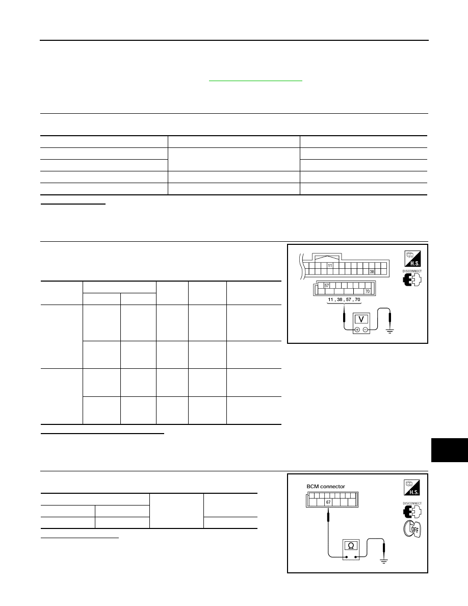
3. Check voltage between BCM harness connector and ground.
Is the measurement value normal?
YES
>> GO TO 3
NO
>> Repair or replace harness.
3.
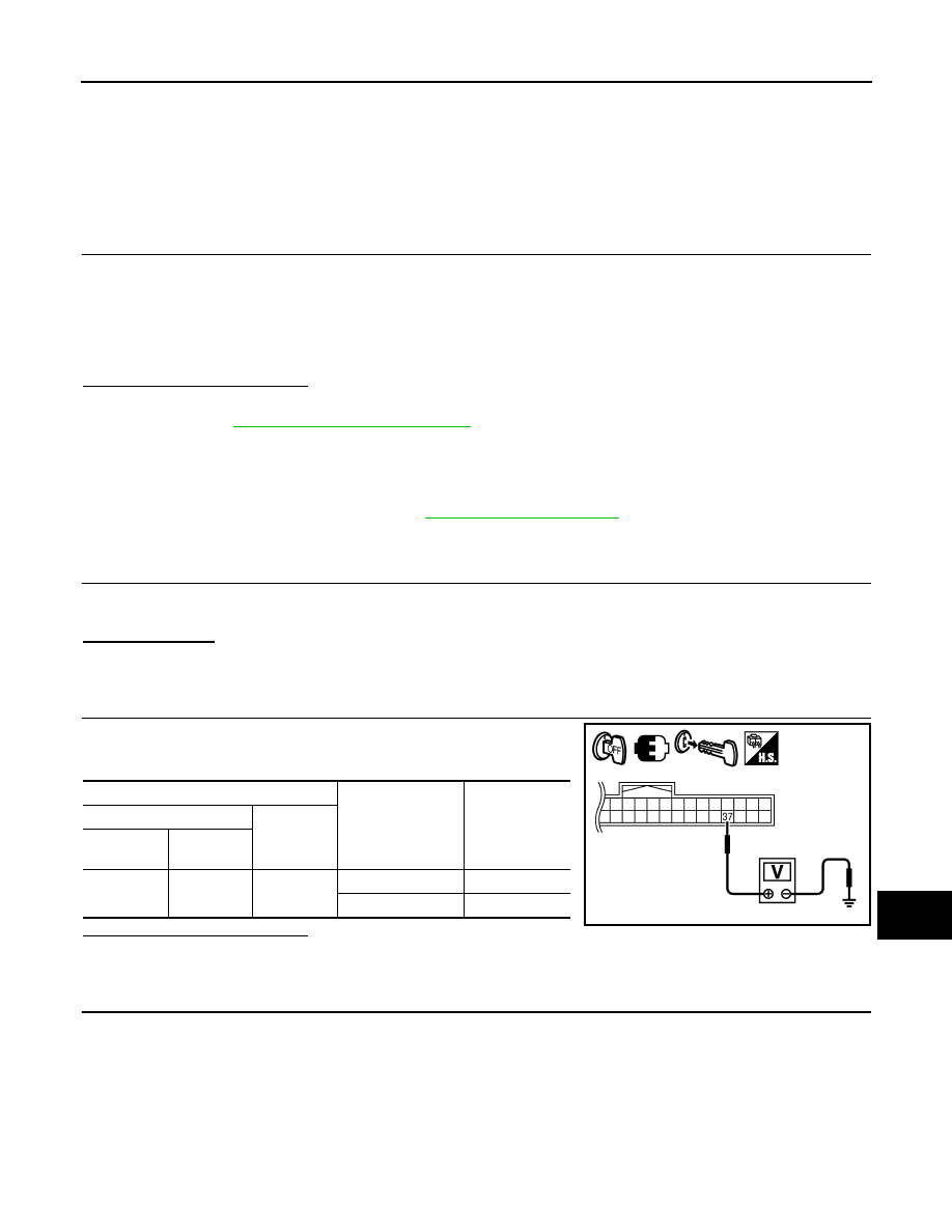
CHECK GROUND CIRCUIT
Check continuity between BCM harness connector and ground.
Does continuity exist?
YES
>> Inspection End.
NO
>> Repair or replace harness.
Terminal No.
Signal name
Fuses and fusible link No.
57
Battery power supply
21 (10A)
70
G (50A)
11
Ignition ACC or ON
4 (10A)
38
Ignition ON or START
1 (10A)
Connector
Terminals
Power
source
Condition
Voltage (V) (Ap-
prox.)
(+)
(-)
M18
11
Ground
ACC
power
supply
Ignition
switch
ACC or
ON
Battery voltage
38
Ground
Ignition
power
supply
Ignition
switch ON
or START
Battery voltage
M20
57
Ground
Battery
power
supply
Ignition
switch
OFF
Battery voltage
70
Ground
Battery
power
supply
Ignition
switch
OFF
Battery voltage
LIIA2415E
BCM
Ground
Continuity
Connector
Terminal
M20
67
Yes
LIIA0915E
August 2012
2012 Pathfinder

WCS-20
< DTC/CIRCUIT DIAGNOSIS >
METER BUZZER CIRCUIT
METER BUZZER CIRCUIT
Description
INFOID:0000000007347541
• The buzzer for warning chime system is installed in the combination meter.
• The combination meter sounds the alarm buzzer based on the signals transmitted from various units.
Component Function Check
INFOID:0000000007347542
1.
CHECK OPERATION OF METER BUZZER
1. Select “BUZZER” of “BCM” on CONSULT.
2. Perform “LIGHT WARN ALM” of “ACTIVE TEST”.
Does meter buzzer activate?
YES
>> Inspection End.
NO
>> Refer to
Diagnosis Procedure
INFOID:0000000007347543
1.
CHECK POWER SUPPLY OF COMBINATION METER
Check power supply of combination meter. Refer to
MWI-31, "COMBINATION METER : Diagnosis Proce-
.
Is the inspection result normal?
YES
>> Replace combination meter. Refer to
MWI-89, "Removal and Installation"
NO
>> Repair power supply circuit of combination meter.
August 2012
2012 Pathfinder

WCS
SEAT BELT BUCKLE SWITCH SIGNAL CIRCUIT
WCS-21
< DTC/CIRCUIT DIAGNOSIS >
C
D
E
F
G
H
I
J
K
L
M
B
A
O
P
SEAT BELT BUCKLE SWITCH SIGNAL CIRCUIT
Description
INFOID:0000000007347544
Transmits a seat belt buckle switch signal to the combination meter.
Component Function Check
INFOID:0000000007347545
1.
CHECK COMBINATION METER INPUT SIGNAL
Select “DATA MONITOR” for “METER/M&A” and check the “SEAT BELT W/L” monitor value.
Is the inspection result normal?
YES
>> Inspection End.
NO
>> Refer to
Diagnosis Procedure
INFOID:0000000007347546
Regarding Wiring Diagram information, refer to
.
1.
CHECK COMBINATION METER INPUT SIGNAL
1. Turn ignition switch ON.
2. Check voltage between combination meter harness connector M24 terminal 24 and ground.
Is the inspection result normal?
YES
>> Replace combination meter. Refer to
MWI-89, "Removal and Installation"
NO
>> GO TO 2
2.
CHECK SEAT BELT BUCKLE SWITCH CIRCUIT
1. Turn ignition switch OFF.
2. Disconnect combination meter connector and seat belt buckle switch LH connector.
3. Check continuity between combination meter harness connector M24 terminal 24 and seat belt buckle
switch LH harness connector B12 terminal 1.
4. Check continuity between combination meter harness connector M24 terminal 24 and ground.
Is the inspection result normal?
YES
>> GO TO 3
NO
>> Repair harness or connector.
3.
CHECK SEAT BELT BUCKLE SWITCH GROUND CIRCUIT
Check continuity between seat belt buckle switch LH harness connector B12 terminal 2 and ground.
Is the inspection result normal?
SEAT BELT W/L
When seat belt is fastened
: OFF
When seat belt is unfastened : ON
24 - Ground
When driver seat belt is fastened
: Approx. 12V
When driver seat belt is unfastened : Approx. 0V
24 - 1
: Continuity should exist.
24 - Ground
: Continuity should not exist.
2 - Ground
: Continuity should exist.
August 2012
2012 Pathfinder
WCS-22
< DTC/CIRCUIT DIAGNOSIS >
SEAT BELT BUCKLE SWITCH SIGNAL CIRCUIT
YES
>> Inspection End.
NO
>> Repair harness or connector.
Component Inspection
INFOID:0000000007347547
1.
CHECK SEAT BELT BUCKLE SWITCH
1. Turn ignition switch OFF.
2. Disconnect the seat belt buckle switch LH connector.
3. Check continuity between the seat belt buckle switch LH terminals 1 and 2.
Is the inspection result normal?
YES
>> Inspection End.
NO
>> Replace the seat belt buckle switch LH.
1– 2
When seat belt is
fastened
: Continuity should not exist.
When seat belt is
unfastened
: Continuity should exist.
August 2012
2012 Pathfinder
WCS
KEY SWITCH SIGNAL CIRCUIT (WITH INTELLIGENT KEY)
WCS-23
< DTC/CIRCUIT DIAGNOSIS >
C
D
E
F
G
H
I
J
K
L
M
B
A
O
P
KEY SWITCH SIGNAL CIRCUIT (WITH INTELLIGENT KEY)
Description
INFOID:0000000007347548
Transmits a key switch signal to the BCM.
Component Function Check
INFOID:0000000007347549
1.
CHECK BCM INPUT SIGNAL
Select “DATA MONITOR” for “BCM” and check the “KEY ON SW” monitor value.
Is the inspection result normal?
YES
>> Inspection End.
NO
>> Refer to
Diagnosis Procedure
INFOID:0000000007347550
Regarding Wiring Diagram information, refer to
.
1.
CHECK FUSE
Check if the key switch and ignition knob switch 10A fuse (No. 31, located in the fuse and fusible link box) is
blown.
Is the fuse blown?
YES
>> Be sure to repair the cause of malfunction before installing new fuse.
NO
>> GO TO 2
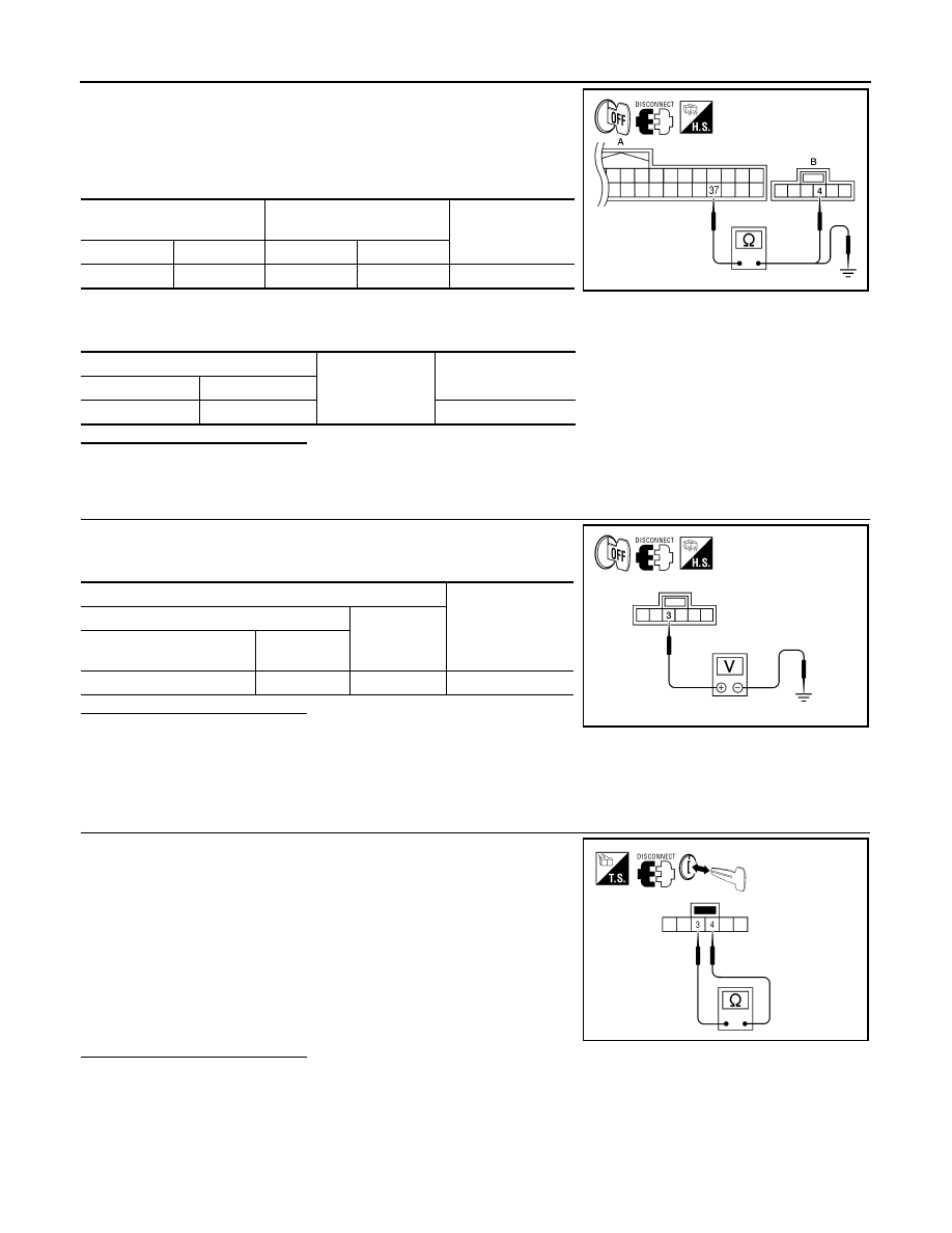
2.
CHECK BCM INPUT SIGNAL
Check voltage between BCM harness connector M18 terminal 37
and ground.
Is the inspection result normal?
YES
>> Inspection End.
NO
>> GO TO 3
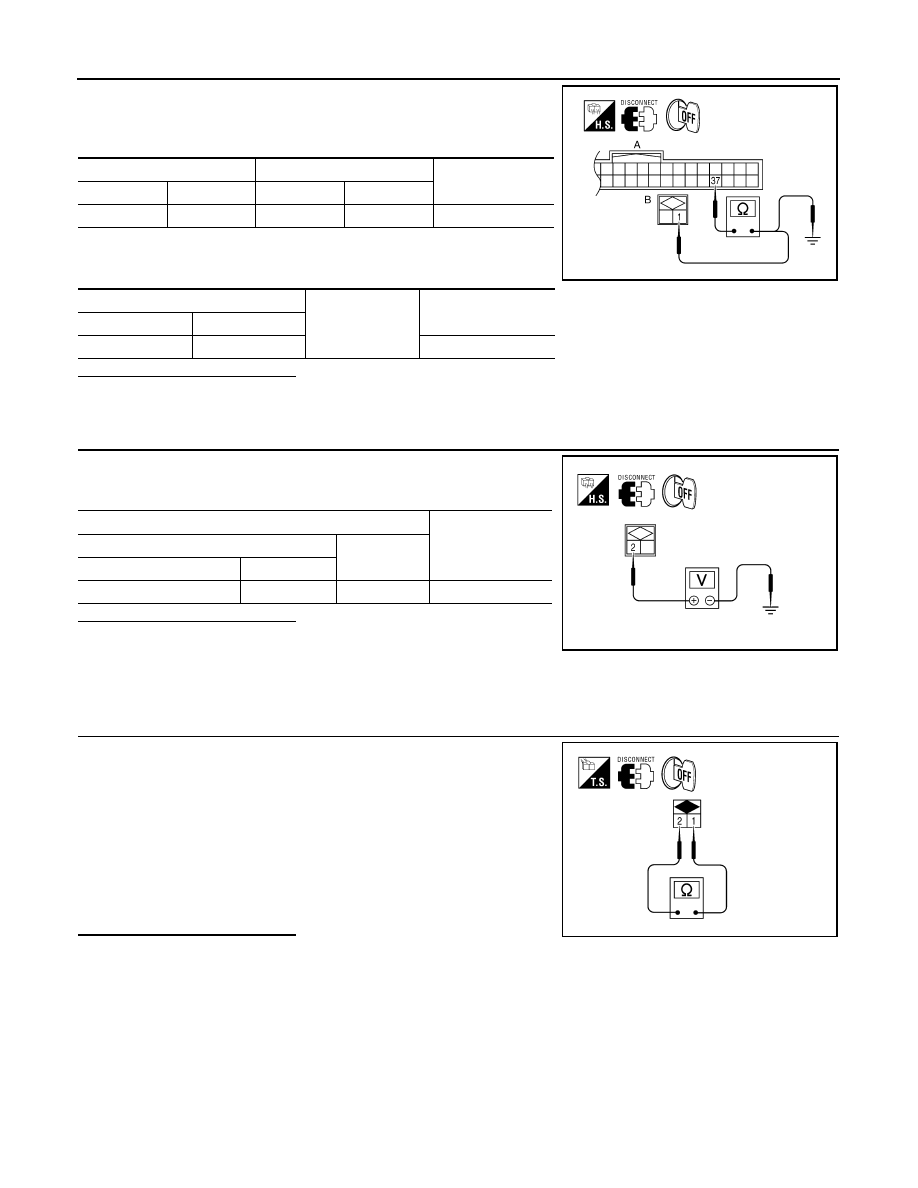
3.
CHECK KEY SWITCH CIRCUIT
KEY ON SW
When key is inserted into key cylinder
: ON
When key is removed from key cylinder : OFF
Terminals
Condition
Voltage
(Approx.)
(+)
(
−
)
BCM
connector
Terminal
M18
37
Ground
Key is inserted
Battery voltage
Key is removed
0
PKIC0721E
August 2012
2012 Pathfinder
WCS-24
< DTC/CIRCUIT DIAGNOSIS >
KEY SWITCH SIGNAL CIRCUIT (WITH INTELLIGENT KEY)
1. Disconnect BCM connector M18 and key switch and ignition
knob switch connector.
2. Check continuity between BCM harness connector M18 (A) ter-
minal 37 and key switch and ignition knob switch harness con-
nector M66 (B) terminal 4.
3. Check continuity between BCM harness connector M18 (A) ter-
minal 37 and ground.
Is the inspection result normal?
YES
>> GO TO 4
NO
>> Repair harness or connector.
4.
CHECK KEY SWITCH POWER SUPPLY CIRCUIT
Check voltage between key switch and ignition knob switch harness
connector M66 terminal 3 and ground.
Is the inspection result normal?
YES
>> Replace key switch and ignition knob switch.
NO
>> Repair harness or connector.
Component Inspection
INFOID:0000000007347551
1.
CHECK KEY SWITCH
1. Turn ignition switch OFF.
2. Disconnect key switch and ignition knob switch connector.
3. Check continuity between key switch and ignition knob switch
terminals 3 and 4.
Is the inspection result normal?
YES
>> Inspection End.
NO
>> Replace key switch and ignition knob switch.
BCM
Key switch and
ignition knob switch
Continuity
Connector
Terminal
Connector
Terminal
M18 (A)
37
M66 (B)
4
Yes
BCM
Ground
Continuity
Connector
Terminal
M18 (A)
37
No
AWNIA0239ZZ
Terminals
Voltage
(Approx.)
(+)
(
−
)
Key switch and ignition
knob switch connector
Terminal
M66
3
Ground
Battery voltage
AWNIA0240ZZ
3 – 4
When key is inserted
into key cylinder
: Continuity should exist.
When key is removed
from key cylinder
: Continuity should not exist.
AWNIA0241ZZ
August 2012
2012 Pathfinder
WCS
KEY SWITCH SIGNAL CIRCUIT (WITHOUT INTELLIGENT KEY)
WCS-25
< DTC/CIRCUIT DIAGNOSIS >
C
D
E
F
G
H
I
J
K
L
M
B
A
O
P
KEY SWITCH SIGNAL CIRCUIT (WITHOUT INTELLIGENT KEY)
Description
INFOID:0000000007347552
Transmits a key switch signal to the BCM.
Component Function Check
INFOID:0000000007347553
1.
CHECK BCM INPUT SIGNAL
Select “DATA MONITOR” for “BCM” and check the “KEY ON SW” monitor value.
Is the inspection result normal?
YES
>> Inspection End.
NO
>> Refer to
Diagnosis Procedure
INFOID:0000000007347554
Regarding Wiring Diagram information, refer to
.
1.
CHECK FUSE
Check if the key switch 10A fuse (No. 25, located in the fuse and fusible link box) is blown.
Is the fuse blown?
YES
>> Be sure to repair the cause of malfunction before installing new fuse.
NO
>> GO TO 2
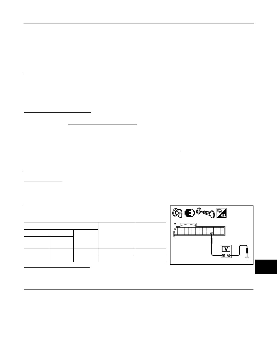
2.
CHECK BCM INPUT SIGNAL
Check voltage between BCM harness connector M18 terminal 37
and ground.
Is the inspection result normal?
YES
>> Inspection End.
NO
>> GO TO 3
3.
CHECK KEY SWITCH CIRCUIT
KEY ON SW
When key is inserted into key cylinder
: ON
When key is removed from key cylinder : OFF
Terminals
Condition
Voltage
(Approx.)
(+)
(
−
)
BCM
connector
Terminal
M18
37
Ground
Key is inserted
Battery voltage
Key is removed
0
PKIC0721E
August 2012
2012 Pathfinder
WCS-26
< DTC/CIRCUIT DIAGNOSIS >
KEY SWITCH SIGNAL CIRCUIT (WITHOUT INTELLIGENT KEY)
1. Disconnect BCM connector M18 and key switch connector.
2. Check continuity between BCM harness connector M18 (A) ter-
minal 37 and key switch harness connector M27 (B) terminal 1.
3. Check continuity between BCM harness connector M18 (A) ter-
minal 37 and ground.
Is the inspection result normal?
YES
>> GO TO 4
NO
>> Repair harness or connector.
4.
CHECK KEY SWITCH POWER SUPPLY CIRCUIT
Check voltage between key switch harness connector M27 terminal
2 and ground.
Is the inspection result normal?
YES
>> Replace key switch.
NO
>> Repair harness or connector.
Component Inspection
INFOID:0000000007347555
1.
CHECK KEY SWITCH
1. Turn ignition switch OFF.
2. Disconnect key switch connector.
3. Check continuity between key switch terminals 1 and 2.
Is the inspection result normal?
YES
>> Inspection End.
NO
>> Replace key switch.
BCM
Key switch
Continuity
Connector
Terminal
Connector
Terminal
M18 (A)
37
M27 (B)
1
Yes
BCM
Ground
Continuity
Connector
Terminal
M18 (A)
37
No
WKIA4102E
Terminals
Voltage
(Approx.)
(+)
(
−
)
Key switch
Terminal
M27
2
Ground
Battery voltage
WKIA4103E
1 – 2
When key is inserted
into key cylinder
: Continuity should exist.
When key is removed
from key cylinder
: Continuity should not exist.
WKIA4101E
August 2012
2012 Pathfinder
Нет комментариевНе стесняйтесь поделиться с нами вашим ценным мнением.
Текст