Nissan Pathfinder (2012 year). Instruction — part 218
FRONT DRIVE SHAFT
DLN-309
< UNIT DISASSEMBLY AND ASSEMBLY >
[TRANSFER: TX15B]
C
E
F
G
H
I
J
K
L
M
A
B
DLN
N
O
P
FRONT DRIVE SHAFT
Disassembly and Assembly
INFOID:0000000007357573
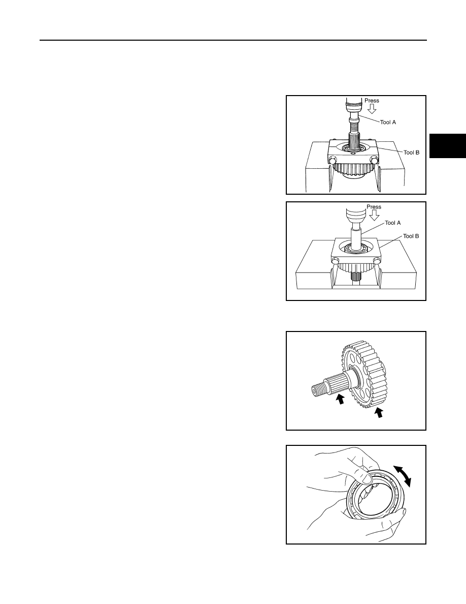
DISASSEMBLY
1. Remove the front bearing using Tools.
2. Remove the rear bearing using Tools.
INSPECTION AFTER DISASSEMBLY
Front Drive Shaft
Check the items below. If necessary, replace them with new ones.
• Damage, peeling, dent, uneven wear and bending of the shaft.
• Excessive wear, damage and peeling of the gear.
Bearing
Check the bearing for damage and rough rotation. If necessary,
replace the bearing with a new one.
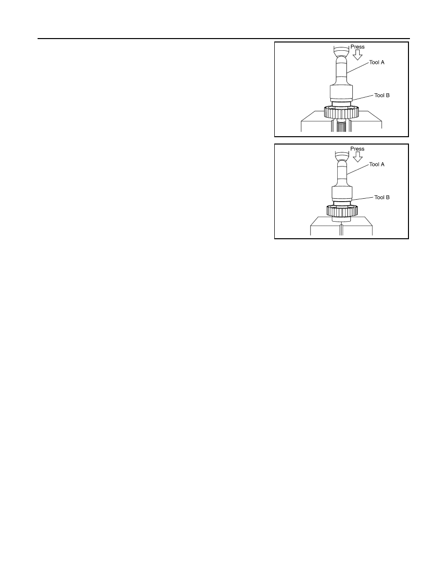
ASSEMBLY
Tool number
(A): ST35300000 ( — )
(B): ST30021000 (J-22912-01)
SDIA2106E
Tool number
(A): ST33710000 ( — )
(B): ST30021000 (J-22912-01)
PDIA0153E
PDIA0154E
MTF0041D
August 2012
2012 Pathfinder
DLN-310
< UNIT DISASSEMBLY AND ASSEMBLY >
[TRANSFER: TX15B]
FRONT DRIVE SHAFT
1. Install the rear bearing using Tools.
2. Install the front bearing using Tools.
Tool number
(A): KV38100500 ( — )
(B): ST30901000 (J-26010-01)
PDIA0155E
Tool number
(A): KV38100500 ( — )
(B): ST30901000 (J-26010-01)
PDIA0156E
August 2012
2012 Pathfinder
SHIFT CONTROL
DLN-311
< UNIT DISASSEMBLY AND ASSEMBLY >
[TRANSFER: TX15B]
C
E
F
G
H
I
J
K
L
M
A
B
DLN
N
O
P
SHIFT CONTROL
Disassembly and Assembly
INFOID:0000000007357574
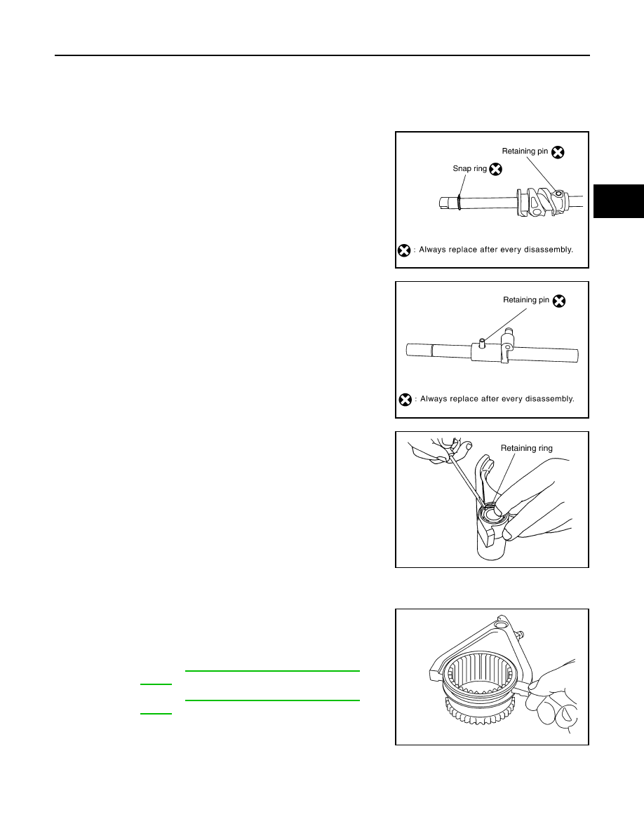
DISASSEMBLY
1. Remove the snap ring.
CAUTION:
Do not reuse snap ring.
2. Remove the retaining pin.
CAUTION:
Do not reuse the retaining pin.
3. Remove the drum cam from the control shift rod.
4. Remove the retaining pin from the L-H shift rod.
CAUTION:
Do not reuse the retaining pin.
5. Remove the 2-4 shift bracket.
6. Remove the retaining ring from the 2-4 shift fork using suitable
tool.
7. Remove the fork guide collar and 2-4 shift fork spring from the 2-
4 shift fork.
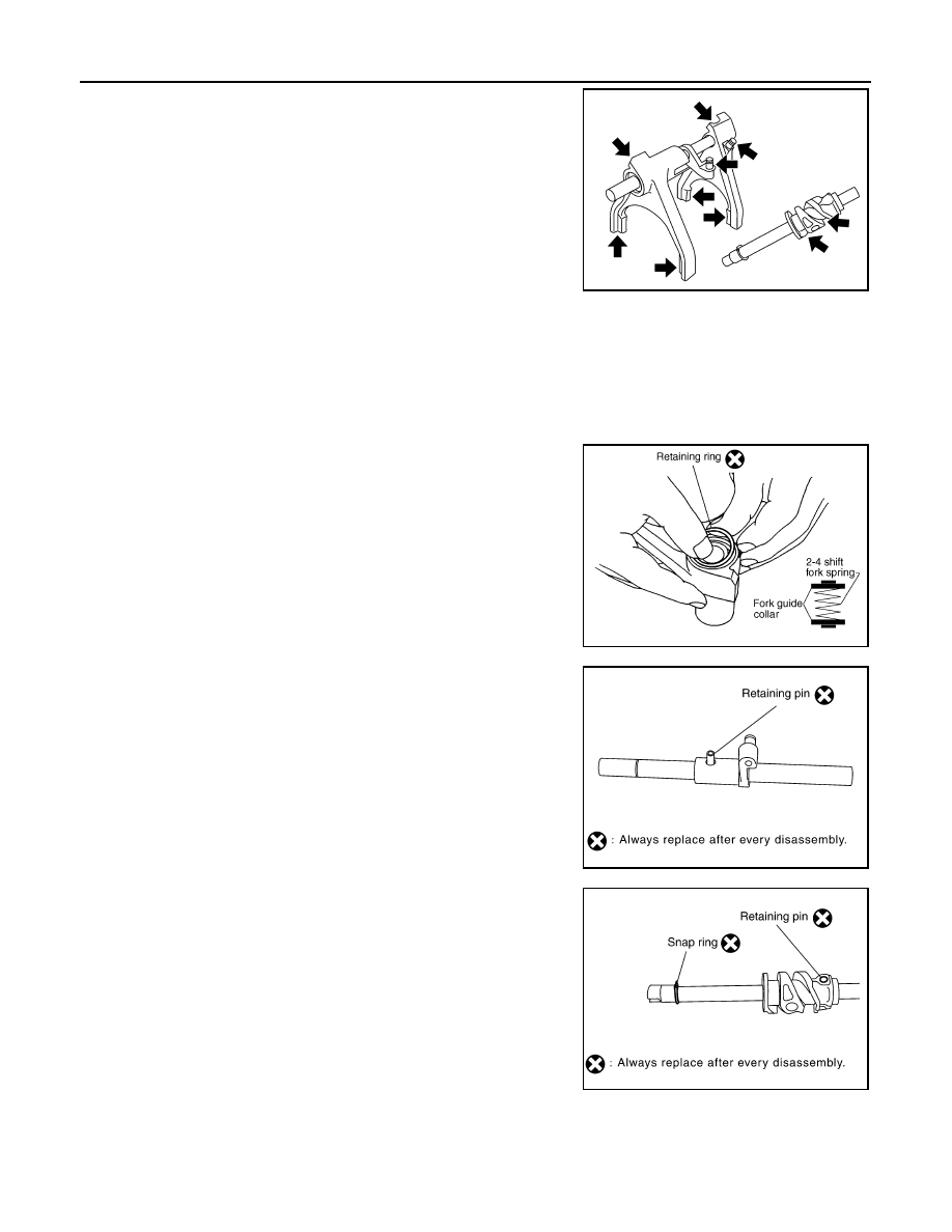
INSPECTION AFTER DISASSEMBLY
Shift Fork
• Measure the clearance between the shift fork and sleeve. If it is out
of specification, replace it with a new one.
Shift Rod and Fork Components
PDIA0122E
PDIA0125E
WDIA0226E
Standard value
2-4
Refer to
DLN-313, "Inspection and Adjust-
L-H
Refer to
DLN-313, "Inspection and Adjust-
PDIA0134E
August 2012
2012 Pathfinder
DLN-312
< UNIT DISASSEMBLY AND ASSEMBLY >
[TRANSFER: TX15B]
SHIFT CONTROL
• Check the working face of the shift rod and fork for wear, partial
wear, abrasion, bending and other abnormality. If any is found,
replace with a new one.
ASSEMBLY
1. Install clevis pin and shift collar to L-H shift fork after assembling them.
CAUTION:
Use caution when installing L-H shift fork, clevis pin or shift collar.
2. Install clevis pin and shift collar to 2-4 shift bracket after assembling them.
CAUTION:
Use caution when installing 2-4 shift bracket.
3. Install guide fork collar and 2-4 shift fork spring to the 2-4 shift
fork, and then secure it with the new retaining ring.
CAUTION:
• Do not reuse retaining ring.
• Be careful with orientation.
4. Install the 2-4shift bracket to the L-H shift rod.
5. Install the new retaining pin evenly to the L-H shift rod.
CAUTION:
Do not reuse retaining pin.
6. Install the drum cam to the control shift rod, and then secure it
with the new retaining pin.
CAUTION:
Do not reuse retaining pin.
7. Install the new snap ring to the control shift rod.
CAUTION:
Do not reuse snap ring.
PDIA0135E
SDIA3391E
PDIA0125E
PDIA0122E
August 2012
2012 Pathfinder

SERVICE DATA AND SPECIFICATIONS (SDS)
DLN-313
< SERVICE DATA AND SPECIFICATIONS (SDS)
[TRANSFER: TX15B]
C
E
F
G
H
I
J
K
L
M
A
B
DLN
N
O
P
SERVICE DATA AND SPECIFICATIONS (SDS)
SERVICE DATA AND SPECIFICATIONS (SDS)
General Specification
INFOID:0000000007357575
Inspection and Adjustment
INFOID:0000000007357576
PINION GEAR END PLAY
Unit: mm (in)
CLEARANCE BETWEEN SHIFT FORK AND SLEEVE
Unit: mm (in)
Applied model
VQ40DE
Transfer model
TX15B
Gear ratio
High
1.000
Low
2.625
Number of teeth
Planetary gear
Sun gear
56
Internal gear
91
Front drive sprocket
38
Front drive shaft
38
Fluid Capacity (Approx)
(US qt, Imp qt)
2.0 (2 1/8, 1 3/4)
Item
Standard
Pinion gear end play
0.1 - 0.7 (0.004 - 0.028)
Item
Standard
2-4 shift fork to 2-4 sleeve
Less than 0.46 (0.018)
L-H shift fork to L-H sleeve
Less than 0.46 (0.018)
August 2012
2012 Pathfinder
DLN-314
< PRECAUTION >
[PROPELLER SHAFT: 2F1310]
PRECAUTIONS
PRECAUTION
PRECAUTIONS
Precaution for Supplemental Restraint System (SRS) "AIR BAG" and "SEAT BELT
PRE-TENSIONER"
INFOID:0000000007357577
The Supplemental Restraint System such as “AIR BAG” and “SEAT BELT PRE-TENSIONER”, used along
with a front seat belt, helps to reduce the risk or severity of injury to the driver and front passenger for certain
types of collision. This system includes seat belt switch inputs and dual stage front air bag modules. The SRS
system uses the seat belt switches to determine the front air bag deployment, and may only deploy one front
air bag, depending on the severity of a collision and whether the front occupants are belted or unbelted.
Information necessary to service the system safely is included in the SR and SB section of this Service Man-
ual.
WARNING:
• To avoid rendering the SRS inoperative, which could increase the risk of personal injury or death in
the event of a collision which would result in air bag inflation, all maintenance must be performed by
an authorized NISSAN/INFINITI dealer.
• Improper maintenance, including incorrect removal and installation of the SRS, can lead to personal
injury caused by unintentional activation of the system. For removal of Spiral Cable and Air Bag
Module, see the SR section.
• Do not use electrical test equipment on any circuit related to the SRS unless instructed to in this
Service Instruction. SRS wiring harnesses can be identified by yellow and/or orange harnesses or har-
ness connectors.
PRECAUTIONS WHEN USING POWER TOOLS (AIR OR ELECTRIC) AND HAMMERS
WARNING:
• When working near the Airbag Diagnosis Sensor Unit or other Airbag System sensors with the Igni-
tion ON or engine running, DO NOT use air or electric power tools or strike near the sensor(s) with a
hammer. Heavy vibration could activate the sensor(s) and deploy the air bag(s), possibly causing
serious injury.
• When using air or electric power tools or hammers, always switch the Ignition OFF, disconnect the
battery, and wait at least 3 minutes before performing any service.
Precaution Necessary for Steering Wheel Rotation After Battery Disconnect
INFOID:0000000007357578
NOTE:
• This Procedure is applied only to models with Intelligent Key system and NATS (NISSAN ANTI-THEFT SYS-
TEM).
• Remove and install all control units after disconnecting both battery cables with the ignition knob in the
″
LOCK
″
position.
• Always use CONSULT to perform self-diagnosis as a part of each function inspection after finishing work. If
DTC is detected, perform trouble diagnosis according to self-diagnostic results.
For models equipped with the Intelligent Key system and NATS, an electrically controlled steering lock mech-
anism is adopted on the key cylinder.
For this reason, if the battery is disconnected or if the battery is discharged, the steering wheel will lock and
steering wheel rotation will become impossible.
If steering wheel rotation is required when battery power is interrupted, follow the procedure below before
starting the repair operation.
OPERATION PROCEDURE
1. Connect both battery cables.
NOTE:
Supply power using jumper cables if battery is discharged.
2. Use the Intelligent Key or mechanical key to turn the ignition switch to the
″
ACC
″
position. At this time, the
steering lock will be released.
3. Disconnect both battery cables. The steering lock will remain released and the steering wheel can be
rotated.
4. Perform the necessary repair operation.
August 2012
2012 Pathfinder
PRECAUTIONS
DLN-315
< PRECAUTION >
[PROPELLER SHAFT: 2F1310]
C
E
F
G
H
I
J
K
L
M
A
B
DLN
N
O
P
5. When the repair work is completed, return the ignition switch to the
″
LOCK
″
position before connecting
the battery cables. (At this time, the steering lock mechanism will engage.)
6. Perform a self-diagnosis check of all control units using CONSULT.
August 2012
2012 Pathfinder
DLN-316
< PREPARATION >
[PROPELLER SHAFT: 2F1310]
PREPARATION
PREPARATION
PREPARATION
Commercial Service Tool
INFOID:0000000007357579
Tool name
Description
Power tool
Loosening nuts, screws and bolts
PIIB1407E
August 2012
2012 Pathfinder
Нет комментариевНе стесняйтесь поделиться с нами вашим ценным мнением.
Текст