Nissan Pathfinder (2012 year). Instruction — part 13
MIRROR SENSOR
ADP-89
< DTC/CIRCUIT DIAGNOSIS >
C
D
E
F
G
H
I
K
L
M
A
B
ADP
N
O
P
MIRROR SENSOR
DRIVER SIDE
DRIVER SIDE : Description
INFOID:0000000007356193
• The mirror sensor LH is installed to the door mirror LH.
• The resistance of 2 sensors (horizontal and vertical) is changed when the door mirror LH is operated.
• Automatic drive positioner control unit calculates the door mirror position according to the change of the volt-
age of 2 sensor input terminals.
DRIVER SIDE : Component Function Check
INFOID:0000000007356194
1.
CHECK FUNCTION
1. Select “MIR/SEN LH U-D”, “MIR/SEN LH R-L” in “Data monitor” with CONSULT.
2. Check mirror sensor (driver side) signal under the following condition.
Is the indication normal?
YES
>> Inspection End.
NO
>> Perform diagnosis procedure. Refer to
ADP-89, "DRIVER SIDE : Diagnosis Procedure"
.
DRIVER SIDE : Diagnosis Procedure
INFOID:0000000007356195
Regarding Wiring Diagram information, refer to
1.
CHECK DOOR MIRROR LH SENSOR SIGNAL
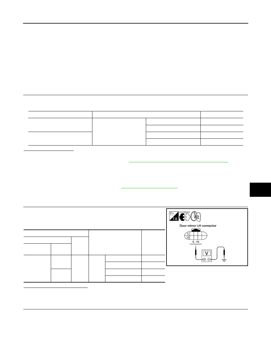
1. Turn ignition switch to ACC.
2. Check voltage between door mirror LH harness connector and
ground.
Is the inspection result normal?
YES
>> GO TO 5
NO
>> GO TO 2
2.
CHECK DOOR MIRROR LH SENSOR CIRCUIT 1
Monitor item
Condition
Value
MIR/SEN LH U-D
Door mirror LH
Close to peak
3.4V
Close to valley
0.6V
MIR/SEN LH R-L
Close to right edge
3.4V
Close to left edge
0.6V
Terminals
Condition
Voltage (V)
(Approx.)
(+)
(–)
Door mirror
LH connector
Terminal
D18
10
Ground
Door
mirror
LH
Close to peak
3.4
Close to valley
0.6
5
Close to right edge
3.4
Close to left edge
0.6
LIIA1766E
August 2012
2012 Pathfinder
ADP-90
< DTC/CIRCUIT DIAGNOSIS >
MIRROR SENSOR
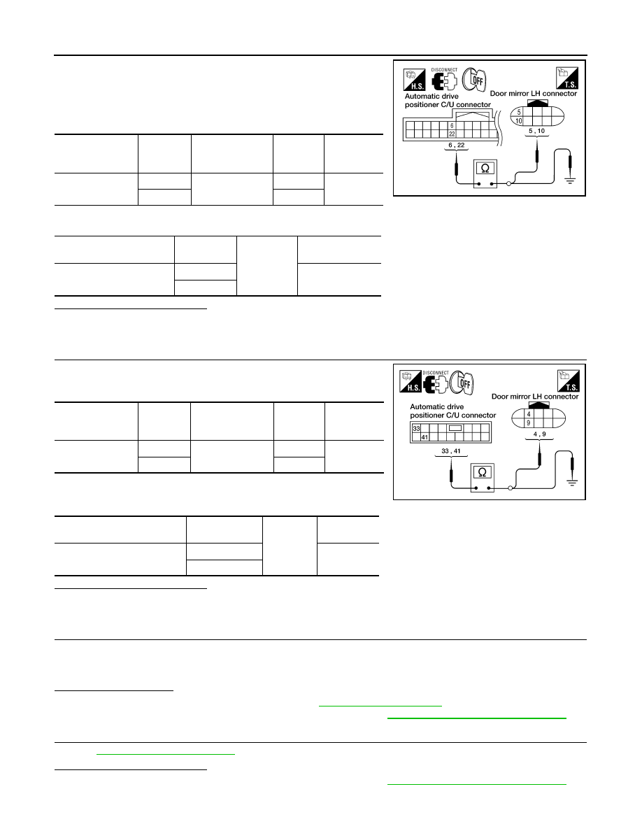
1. Turn ignition switch OFF.
2. Disconnect automatic drive positioner control unit and door mir-
ror LH.
3. Check continuity between automatic drive positioner control unit
harness connector and door mirror LH harness connector.
4. Check continuity between automatic drive positioner control unit harness connector and ground.
Is the inspection result normal?
YES
>> GO TO 3
NO
>> Repair or replace harness.
3.
CHECK DOOR MIRROR LH SENSOR CIRCUIT 2
1. Check continuity between automatic drive positioner control unit
harness connector and door mirror LH harness connector.
2. Check continuity between automatic drive positioner control unit
harness connector and ground.
Is the inspection result normal?
YES
>> GO TO 4
NO
>> Repair or replace harness.
4.
CHECK PEDAL ADJUSTING OPERATION
1. Connect driver seat control unit connector and door mirror LH connector.
2. Turn ignition switch ON.
3. Check pedal adjusting operation with memory function.
Is the operation normal?
YES
>> Replace door mirror actuator LH. Refer to
NO
>> Replace automatic drive positioner control unit. Refer to
ADP-150, "Removal and Installation"
5.
CHECK INTERMITTENT INCIDENT
GI-37, "Intermittent Incident"
Is the inspection result normal?
YES
>> Replace automatic drive positioner control unit. Refer to
ADP-150, "Removal and Installation"
NO
>> Repair or replace the malfunctioning part.
Automatic drive
positioner control
unit connector
Terminal
Door mirror LH
connector
Terminal
Continuity
M33
6
D18
10
Yes
22
5
Automatic drive positioner
control unit connector
Terminal
Ground
Continuity
M33
6
No
22
LIIA1768E
Automatic drive
positioner control
unit connector
Terminal
Door mirror LH
connector
Terminal
Continuity
M34
33
D18
4
Yes
41
9
Automatic drive positioner
control unit connector
Terminal
Ground
Continuity
M34
33
No
41
LIIA1767E
August 2012
2012 Pathfinder
MIRROR SENSOR
ADP-91
< DTC/CIRCUIT DIAGNOSIS >
C
D
E
F
G
H
I
K
L
M
A
B
ADP
N
O
P
PASSENGER SIDE
PASSENGER SIDE : Description
INFOID:0000000007356196
• The mirror sensor RH is installed to the door mirror RH.
• The resistance of 2 sensors (horizontal and vertical) is changed when the door mirror RH is operated.
• Automatic drive positioner control unit calculates the door mirror position according to the change of the volt-
age of 2 sensor input terminals.
PASSENGER SIDE : Component Function Check
INFOID:0000000007356197
1.
CHECK FUNCTION
1. Select “MIR/SEN RH U-D”, “MIR/SEN RH R-L” in “Data monitor” with CONSULT.
2. Check the mirror sensor RH signal under the following conditions.
Is the indication normal?
YES
>> Inspection End.
NO
>> Perform diagnosis procedure. Refer to
ADP-91, "PASSENGER SIDE : Diagnosis Procedure"
.
PASSENGER SIDE : Diagnosis Procedure
INFOID:0000000007356198
Regarding Wiring Diagram information, refer to
1.
CHECK DOOR MIRROR RH SENSOR SIGNAL
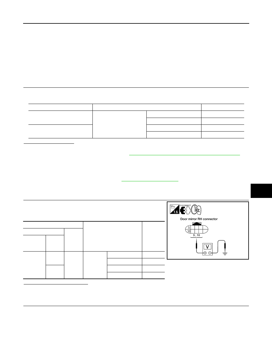
1. Turn ignition switch to ACC.
2. Check voltage between door mirror RH harness connector and
ground.
Is the inspection result normal?
YES
>> GO TO 5
NO
>> GO TO 2
2.
CHECK DOOR MIRROR RH SENSOR HARNESS CONTINUITY
Monitor item
Condition
Value
MIR/SEN RH U-D
Door mirror RH
Close to peak
3.4V
Close to valley
0.6V
MIR/SEN RH R-L
Close to right edge
3.4V
Close to left edge
0.6V
Terminals
Condition
Voltage (V)
(Approx.)
(+)
(–)
Door mirror
RH con-
nector
Terminal
D118
10
Ground
Door mirror
RH
Close to peak
3.4
Close to valley
0.6
5
Close to right edge
3.4
Close to left edge
0.6
LIIA1769E
August 2012
2012 Pathfinder
ADP-92
< DTC/CIRCUIT DIAGNOSIS >
MIRROR SENSOR
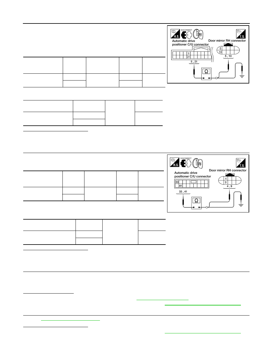
1. Turn ignition switch OFF.
2. Disconnect automatic drive positioner control unit and door mir-
ror RH.
3. Check continuity between automatic drive positioner control unit
harness connector and door mirror RH harness connector.
4. Check continuity between automatic drive positioner control unit harness connector and ground.
Is the inspection result normal?
YES
>> GO TO 3
NO
>> Repair or replace harness.
3.
CHECK DOOR MIRROR RH SENSOR POWER SUPPLY CIRCUIT
1. Check continuity between automatic drive positioner control unit
harness connector and door mirror RH harness connector.
2. Check continuity between automatic drive positioner control unit
harness connector and ground.
Is the inspection result normal?
YES
>> GO TO 4
NO
>> Repair or replace harness.
4.
CHECK PEDAL ADJUSTING OPERATION
1. Connect driver seat control unit connector and door mirror RH connector.
2. Turn ignition switch ON.
3. Check pedal adjusting operation with memory function.
Is the operation normal?
YES
>> Replace door mirror actuator RH. Refer to
.
NO
>> Replace automatic drive positioner control unit. Refer to
ADP-150, "Removal and Installation"
5.
CHECK INTERMITTENT INCIDENT
GI-37, "Intermittent Incident"
Is the inspection result normal?
YES
>> Replace automatic drive positioner control unit. Refer to
ADP-150, "Removal and Installation"
NO
>> Repair or replace the malfunctioning part.
Automatic drive posi-
tioner control unit
connector
Terminal
Door mirror RH
connector
Terminal
Continuity
M33
5
D118
10
Yes
21
5
Automatic drive positioner
control unit connector
Terminal
Ground
Continuity
M33
5
No
21
LIIA1772E
Automatic drive posi-
tioner control unit
connector
Terminal
Door mirror RH
connector
Terminal
Continuity
M34
33
D118
4
Yes
41
9
Automatic drive positioner
control unit connector
Terminal
Ground
Continuity
M34
33
No
41
LIIA1771E
August 2012
2012 Pathfinder

SLIDING MOTOR
ADP-93
< DTC/CIRCUIT DIAGNOSIS >
C
D
E
F
G
H
I
K
L
M
A
B
ADP
N
O
P
SLIDING MOTOR
Description
INFOID:0000000007356199
• The sliding motor LH is installed to the seat frame assembly.
• The sliding motor LH is installed with the driver seat control unit.
• The seat is slid forward/backward by changing the rotation direction of sliding motor LH.
Component Function Check
INFOID:0000000007356200
1.
CHECK FUNCTION
1. Select “SEAT SLIDE” in “Active test” mode with CONSULT.
2. Check the sliding motor LH operation.
Is the operation of relevant parts normal?
YES
>> Inspection End.
NO
>> Perform diagnosis procedure. Refer to
Diagnosis Procedure
INFOID:0000000007356201
Regarding Wiring Diagram information, refer to
1.
CHECK SLIDING MOTOR LH POWER SUPPLY
1. Turn the ignition switch to ACC.
2. Perform “Active test” (“SEAT SLIDE”) with CONSULT.
3. Check voltage between driver seat control unit harness connec-
tor and ground.
Is the inspection result normal?
YES
>> Replace sliding motor LH. Refer to
NO
>> GO TO 2
2.
CHECK SLIDING MOTOR LH CIRCUIT
Test Item
Description
SEAT SLIDE
OFF
Seat sliding
Stop
FR
Forward
RR
Backward
Terminal
Test Item
Voltage (V)
(Approx.)
(+)
(-)
Driver seat
control unit
connector
Terminal
B203
35
Ground
SEAT
SLIDE
OFF
0
FR (forward)
Battery voltage
RR (backward)
0
42
OFF
0
FR (forward)
0
RR (backward) Battery voltage
PIIA4801E
August 2012
2012 Pathfinder
ADP-94
< DTC/CIRCUIT DIAGNOSIS >
SLIDING MOTOR
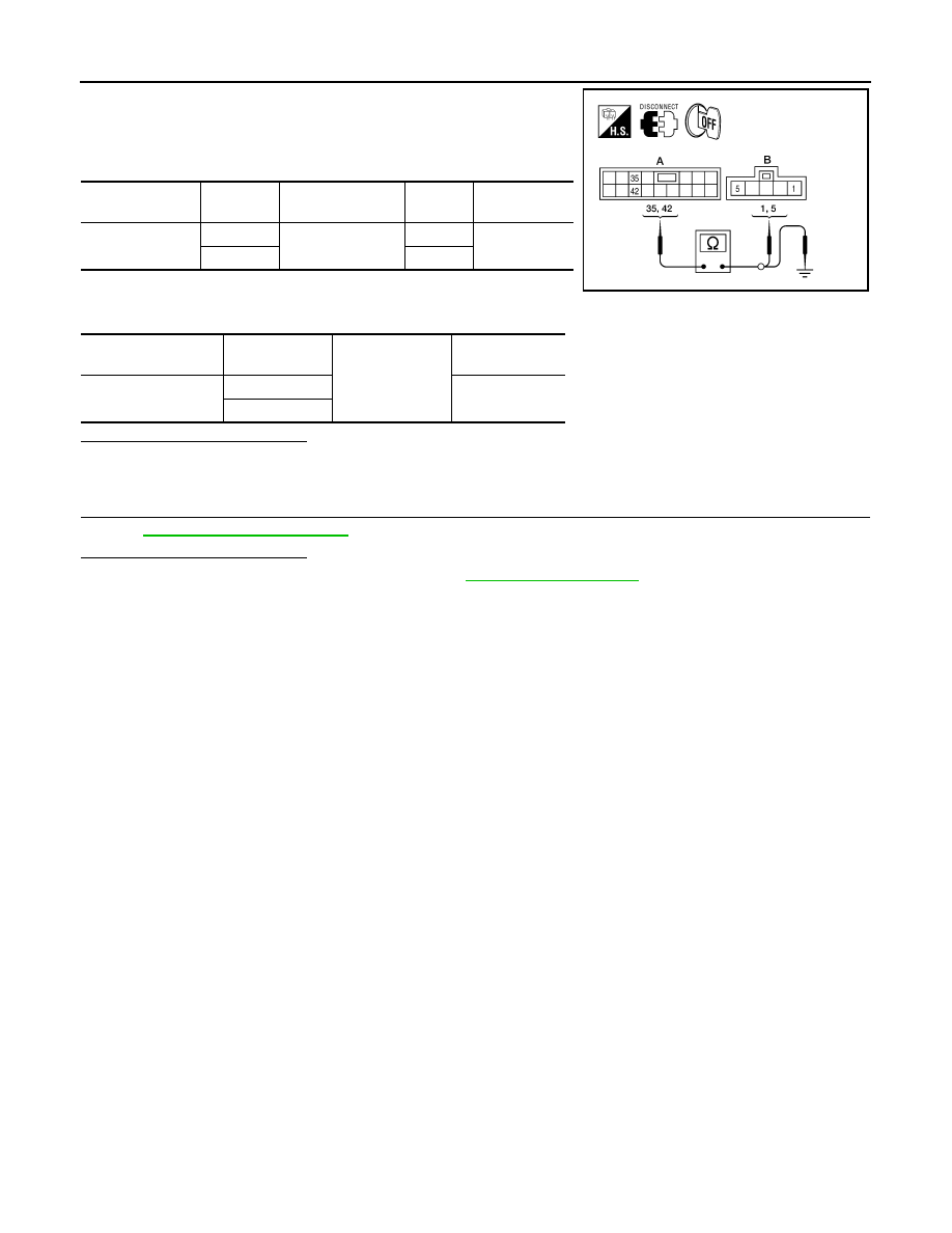
1. Turn ignition switch OFF.
2. Disconnect driver seat control unit and sliding motor LH.
3. Check continuity between driver seat control unit harness con-
nector and sliding motor LH harness connector.
4. Check continuity between driver seat control unit harness con-
nector and ground.
Is the inspection result normal?
YES
>> GO TO 3
NO
>> Repair or replace harness.
3.
CHECK INTERMITTENT INCIDENT
GI-37, "Intermittent Incident"
Is the inspection result normal?
YES
>> Replace driver seat control unit. Refer to
NO
>> Repair or replace the malfunctioning part.
Driver seat control
unit connector
Terminal
Sliding motor LH
connector
Terminal
Continuity
B203 (A)
35
B204 (B)
5
Yes
42
1
Driver seat control
unit connector
Terminal
Ground
Continuity
B203 (A)
35
No
42
ALJIA0470ZZ
August 2012
2012 Pathfinder
RECLINING MOTOR
ADP-95
< DTC/CIRCUIT DIAGNOSIS >
C
D
E
F
G
H
I
K
L
M
A
B
ADP
N
O
P
RECLINING MOTOR
Description
INFOID:0000000007356202
• The reclining motor LH is installed to the seat back frame.
• The reclining motor LH is activated with the driver seat control unit.
• The seatback is reclined forward/backward by changing the rotation direction of reclining motor LH.
Component Function Check
INFOID:0000000007356203
1.
CHECK FUNCTION
1. Select “SEAT RECLINING” in “Active test” mode with CONSULT.
2. Check the reclining motor LH operation.
Is the operation of relevant parts normal?
YES
>> Inspection End.
NO
>> Perform diagnosis procedure. Refer to
Diagnosis Procedure
INFOID:0000000007356204
Regarding Wiring Diagram information, refer to
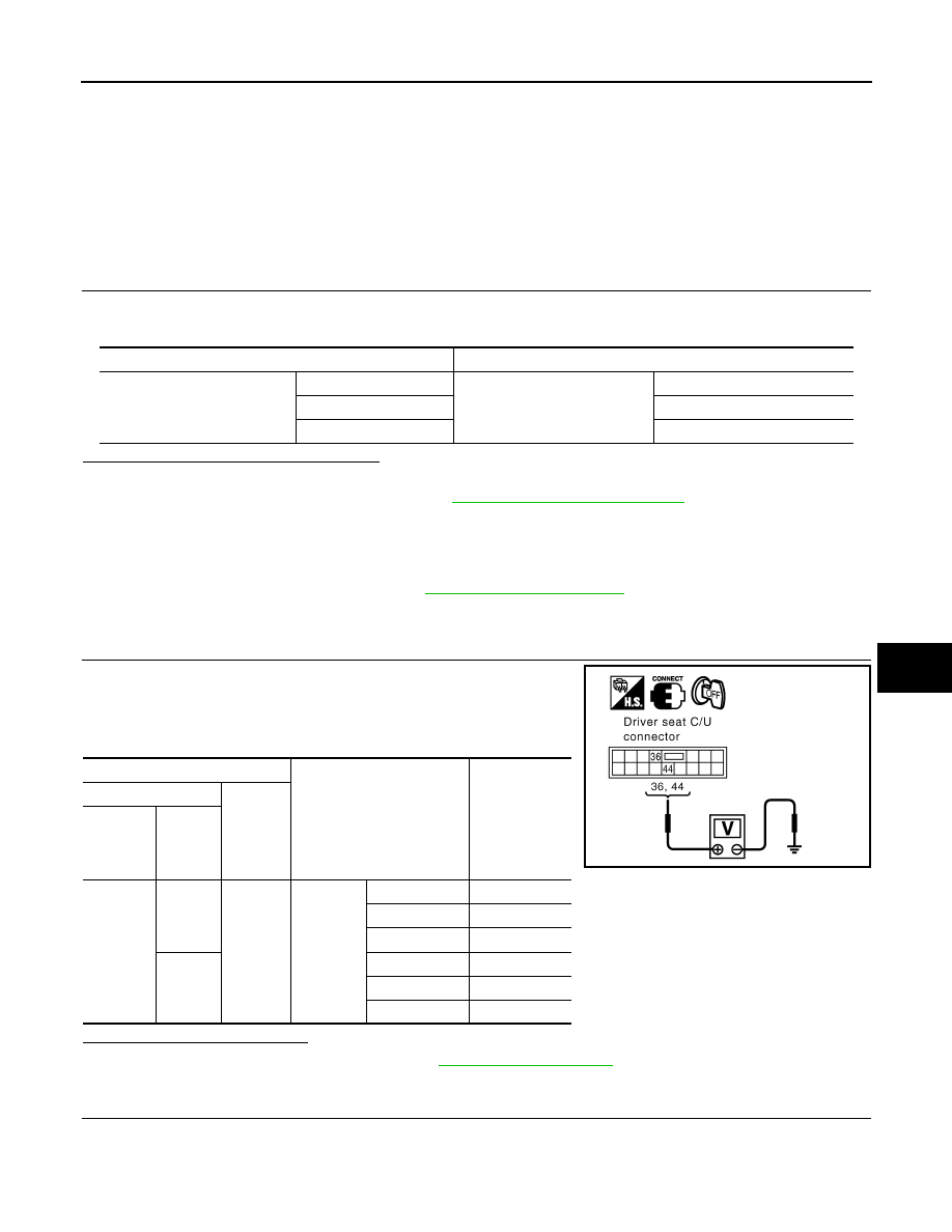
1.
CHECK RECLINING MOTOR LH POWER SUPPLY
1. Turn the ignition switch to ACC.
2. Perform “Active test” (“SEAT RECLINING”) with CONSULT.
3. Check voltage between driver seat control unit harness connec-
tor and ground.
Is the inspection result normal?
YES
>> Replace reclining motor LH. Refer to
NO
>> GO TO 2
2.
CHECK RECLINING MOTOR LH CIRCUIT
Test Item
Description
SEAT RECLINING
OFF
Seat reclining
Stop
FR
Forward
RR
Backward
Terminal
Test Item
Voltage (V)
(Approx.)
(+)
(-)
Driver
seat con-
trol unit
connector
Terminal
B203
36
Ground
SEAT RE-
CLINING
OFF
0
FR (forward)
Battery voltage
RR (backward)
0
44
OFF
0
FR (forward)
0
RR (backward)
Battery voltage
PIIA4802E
August 2012
2012 Pathfinder
ADP-96
< DTC/CIRCUIT DIAGNOSIS >
RECLINING MOTOR
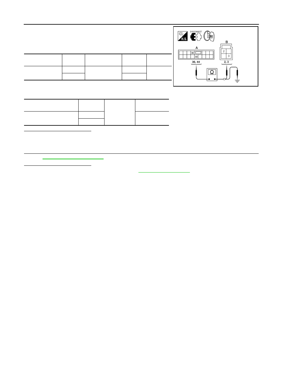
1. Turn ignition switch OFF.
2. Disconnect driver seat control unit and reclining motor LH.
3. Check continuity between driver seat control unit harness con-
nector and reclining motor harness connector.
4. Check continuity between driver seat control unit harness con-
nector and ground.
Is the inspection result normal?
YES
>> GO TO 3
NO
>> Repair or replace harness.
3.
CHECK INTERMITTENT INCIDENT
GI-37, "Intermittent Incident"
Is the inspection result normal?
YES
>> Replace driver seat control unit. Refer to
NO
>> Repair or replace the malfunctioning part.
Driver seat control
unit connector
Terminal
Reclining motor LH
connector
Terminal
Continuity
B203 (A)
36
B232 (B)
2
Yes
44
3
Driver seat control unit
connector
Terminal
Ground
Continuity
B203 (A)
36
No
44
ALJIA0471ZZ
August 2012
2012 Pathfinder
Нет комментариевНе стесняйтесь поделиться с нами вашим ценным мнением.
Текст