Nissan Pathfinder (2012 year). Instruction — part 570

S CONNECTOR CIRCUIT
STR-17
< DTC/CIRCUIT DIAGNOSIS >
C
D
E
F
G
H
I
J
K
L
M
A
STR
N
P
O
Are the continuity test results as specified?
YES
>> Further inspection necessary. Refer to
STR-5, "Work Flow (With GR8-1200 NI)"
NO
>> Repair the harness.
Diagnosis Procedure - VK56DE
INFOID:0000000007358913
Regarding Wiring Diagram information, refer to
STR-23, "Wiring Diagram - VK56DE"
.
CAUTION:
Before testing, perform the following procedure to ensure the engine cannot start.
1. Remove fuel pump fuse.
2. Crank or start the engine (where possible) until the fuel pressure is released.
1.
CHECK STARTER MOTOR MAGNETIC SWITCH CIRCUIT
1. Turn ignition switch OFF.
2. Disconnect starter motor connector F17.
3. Shift transmission into park or neutral.
4. Check voltage between starter motor harness connector F17 terminal 2 and ground with the ignition in
START.
Is battery voltage present?
YES
>> Magnetic switch circuit is OK. Further inspection necessary. Refer to
STR-9, "Work Flow (Without GR8-1200 NI)"
.
NO
>> GO TO 2
2.
CHECK CONNECTOR
1. Turn ignition switch OFF.
2. Check the IPDM E/R harness connector E120 and starter motor harness connector F17 for damage, bent
pins and loose connections.
Is the inspection result normal?
YES
>> GO TO 3
NO
>> Repair the terminal and connector.
3.
CHECK HARNESS CONTINUITY (OPEN CIRCUIT)
1. Disconnect IPDM E/R connector E120.
2. Check continuity between starter motor harness connector F17 terminal 2 and IPDM E/R harness connec-
tor E120 terminal 19.
3. Check continuity between starter motor harness connector F17 terminal 2 and ground.
Starter motor
—
Continuity
Connector
Terminal
E207 (A)
1
Ground
No
(+)
(-)
Condition
Voltage
Connector
Terminal
F17
2
Ground
While cranking the engine
Battery voltage
Starter motor
IPDM E/R
Continuity
Connector
Terminal
Connector
Terminal
F17
2
E120
19
Yes
August 2012
2012 Pathfinder

STR-18
< DTC/CIRCUIT DIAGNOSIS >
S CONNECTOR CIRCUIT
Are the continuity test results as specified?
YES
>> Further inspection necessary. Refer to
STR-5, "Work Flow (With GR8-1200 NI)"
or
NO
>> Repair the harness.
Starter motor
—
Continuity
Connector
Terminal
F17
2
Ground
No
August 2012
2012 Pathfinder
STARTING SYSTEM
STR-19
< WIRING DIAGRAM >
C
D
E
F
G
H
I
J
K
L
M
A
STR
N
P
O
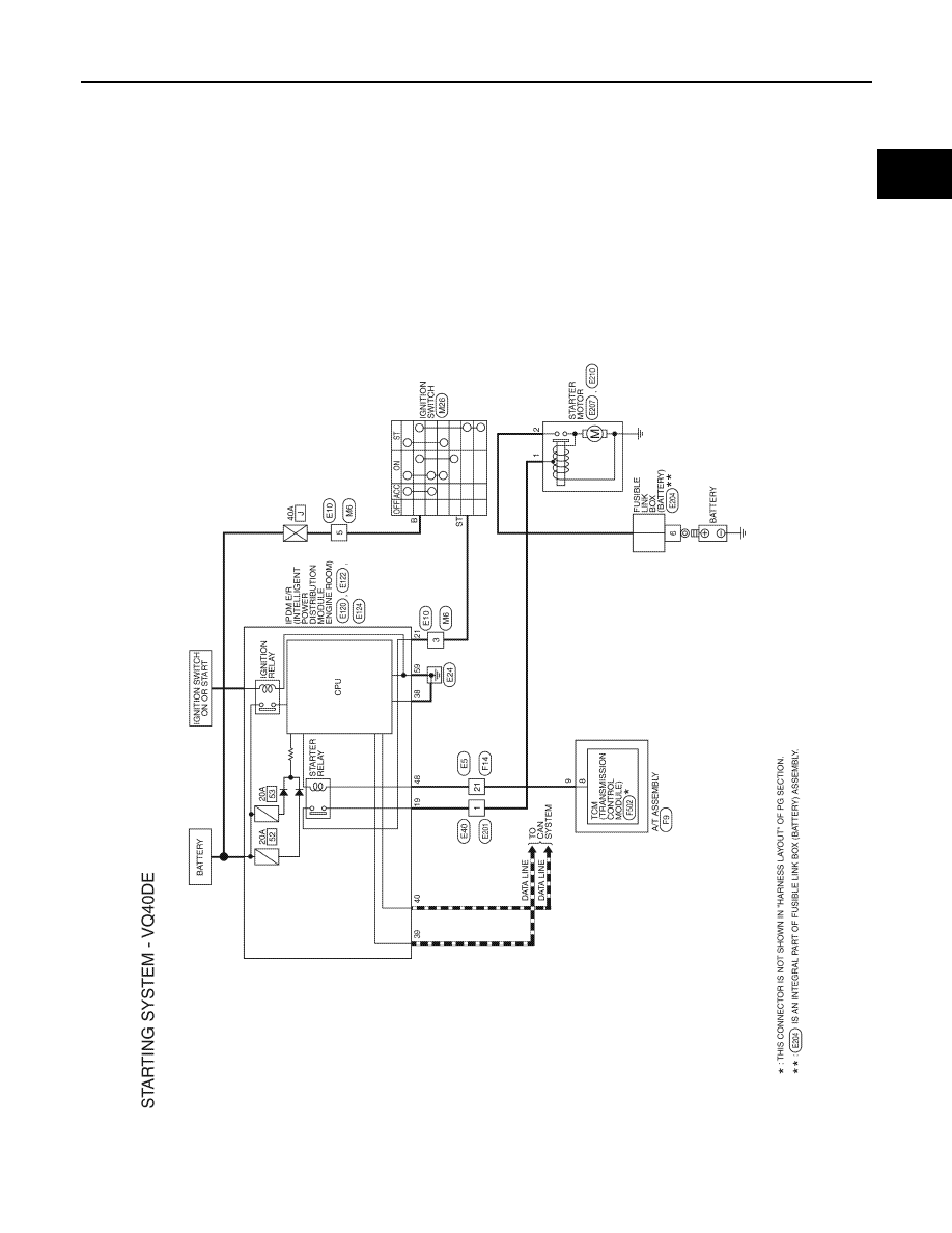
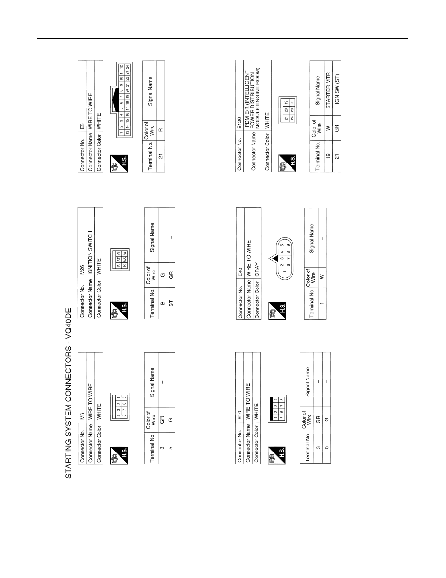
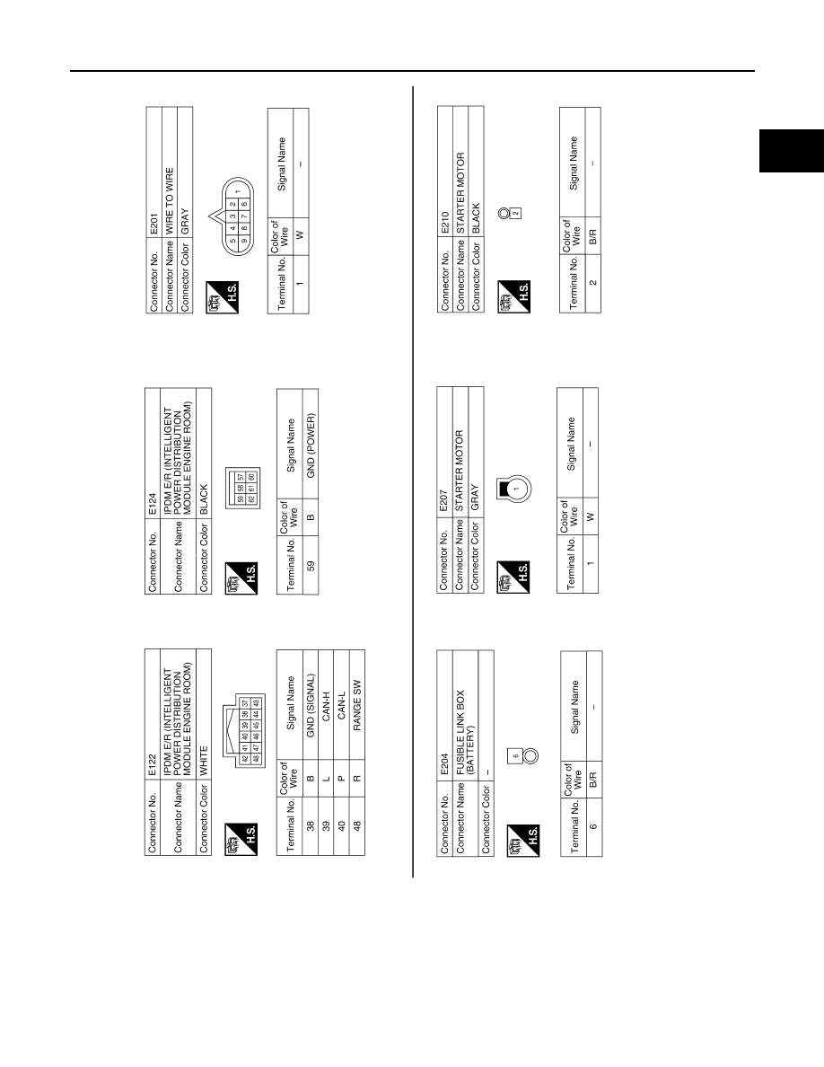
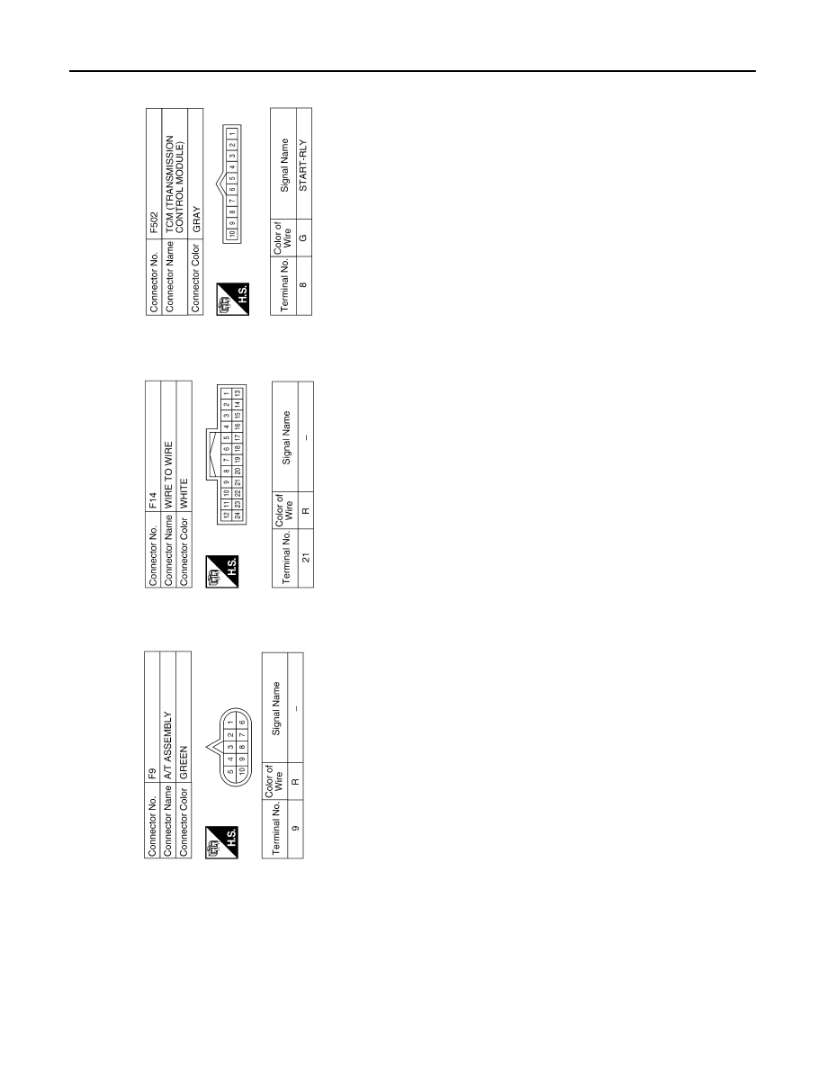
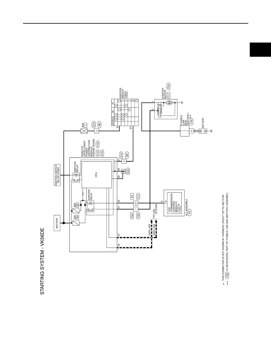
WIRING DIAGRAM
STARTING SYSTEM
Wiring Diagram - VQ40DE
INFOID:0000000007358914
ABBWA0186GB
August 2012
2012 Pathfinder
STR-20
< WIRING DIAGRAM >
STARTING SYSTEM
ABBIA0398GB
August 2012
2012 Pathfinder
STARTING SYSTEM
STR-21
< WIRING DIAGRAM >
C
D
E
F
G
H
I
J
K
L
M
A
STR
N
P
O
ABBIA1213GB
August 2012
2012 Pathfinder
STR-22
< WIRING DIAGRAM >
STARTING SYSTEM
ABBIA1214GB
August 2012
2012 Pathfinder
STARTING SYSTEM
STR-23
< WIRING DIAGRAM >
C
D
E
F
G
H
I
J
K
L
M
A
STR
N
P
O
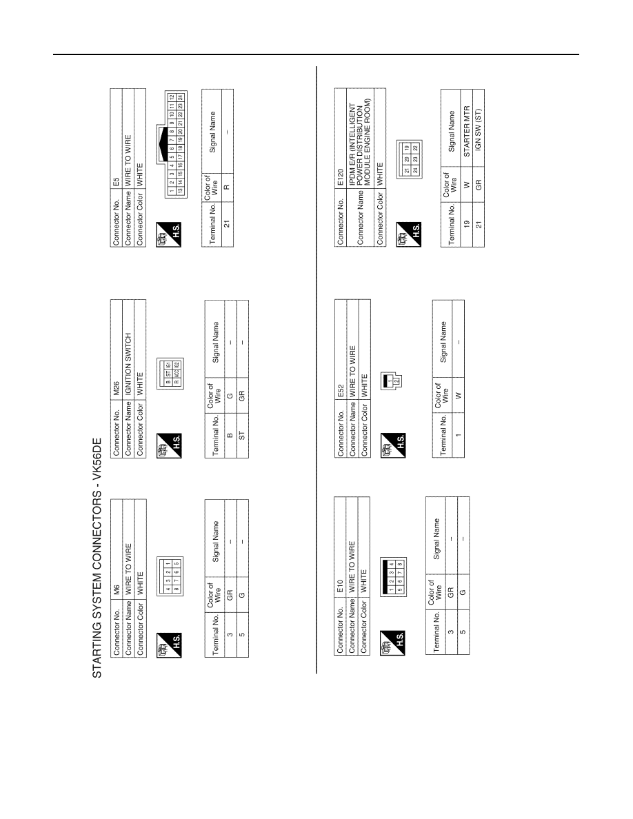
Wiring Diagram - VK56DE
INFOID:0000000007358915
ABBWA0836GB
August 2012
2012 Pathfinder
STR-24
< WIRING DIAGRAM >
STARTING SYSTEM
ABBIA0399GB
August 2012
2012 Pathfinder
Нет комментариевНе стесняйтесь поделиться с нами вашим ценным мнением.
Текст