Nissan Pathfinder (2012 year). Instruction — part 338
P0448 EVAP CANISTER VENT CONTROL VALVE
EC-785
< DTC/CIRCUIT DIAGNOSIS >
[VK56DE]
C
D
E
F
G
H
I
J
K
L
M
A
EC
N
P
O
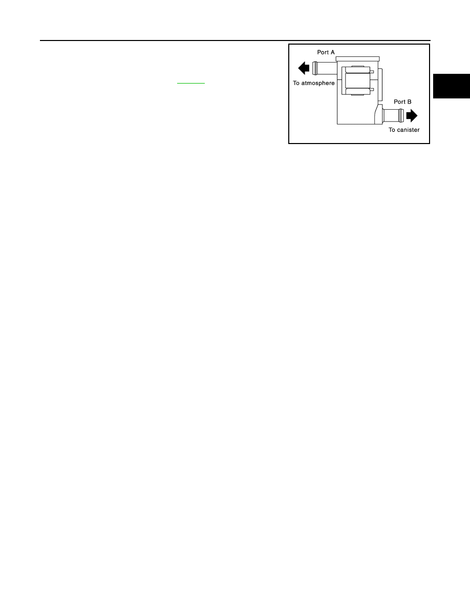
4. Blow air into port A and check that it flows freely out of port B.
5. Block port B.
6. Blow air into port A and check that there is no leakage.
7. If NG, replace drain filter. Refer to
PBIB3641E
August 2012
2012 Pathfinder
EC-786
< DTC/CIRCUIT DIAGNOSIS >
[VK56DE]
P0451 EVAP CONTROL SYSTEM PRESSURE SENSOR
P0451 EVAP CONTROL SYSTEM PRESSURE SENSOR
Component Description
INFOID:0000000007358654
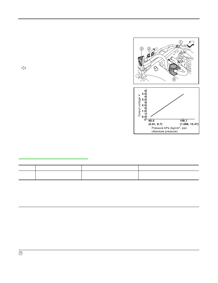
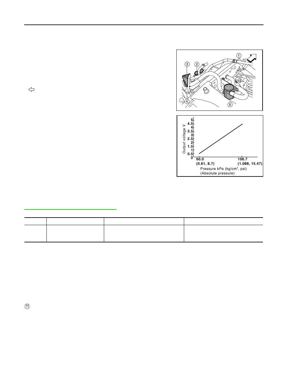
The EVAP control system pressure sensor (2) detects pressure in
the purge line. The sensor output voltage to the ECM increases as
pressure increases.
• Fuel filler pipe (top of frame view) (1)
• EVAP canister vent control valve (3)
• EVAP canister (4)
• Drain filter (5)
•
: Vehicle front
On Board Diagnosis Logic
INFOID:0000000007358655
NOTE:
If DTC P0451 is displayed with DTC P0643, first perform the trouble diagnosis for DTC P0643. Refer to
EC-836, "DTC Confirmation Procedure"
.
DTC Confirmation Procedure
INFOID:0000000007358656
NOTE:
Never remove fuel filler cap during DTC confirmation procedure.
1.
PRECONDITIONING
If DTC Confirmation Procedure has been previously conducted, always perform the following procedure
before conducting the next test.
1. Turn ignition switch OFF and wait at least 10 seconds.
2. Turn ignition switch ON.
3. Turn ignition switch OFF and wait at least 10 seconds.
With CONSULT>>GO TO 2.
Without CONSULT>>GO TO 5.
2.
PERFORM DTC CONFIRMATION PROCEDURE-1
With CONSULT
1. Start engine and let it idle for least 40 seconds.
NOTE:
Do not depress accelerator pedal even slightly.
2. Check 1st trip DTC.
AWBIA0134ZZ
PBIB3370E
DTC No.
Trouble diagnosis name
DTC detecting condition
Possible cause
P0451
0451
EVAP control system pressure
sensor performance
ECM detects a sloshing signal from the
EVAP control system pressure sensor
• Harness or connectors
• EVAP control system pressure sensor
August 2012
2012 Pathfinder

P0451 EVAP CONTROL SYSTEM PRESSURE SENSOR
EC-787
< DTC/CIRCUIT DIAGNOSIS >
[VK56DE]
C
D
E
F
G
H
I
J
K
L
M
A
EC
N
P
O
Is 1st trip DTC detected?
YES
>> Proceed to
.
NO
>> GO TO 3.
3.
PERFORM DTC CONFIRMATION PROCEDURE-2
With CONSULT
1. Select “EVAP DIAG READY” in “DATA MONITOR” mode of “ENGINE”.
2. Let it idle until “OFF” of “EVAP DIAG READY” changes to “ON”.
NOTE:
It will take at most 2 hours until “OFF” of “EVAP DIAG READY” changes to “ON”.
3. Turn ignition switch OFF and wait at least 90 minutes.
NOTE:
Never turn ignition switch ON during 90 minutes.
4. Turn ignition switch ON.
5. Select “EVAP LEAK DIAG” in “DATA MONITOR” mode of “ENGINE”.
6. Check that “EVAP LEAK DIAG” indication.
Which is displayed on CONSULT?
CMPLT >> GO TO 4.
YET
>> 1. Perform DTC CONFIRMATION PROCEDURE again.
2. GO TO 1.
4.
PERFORM DTC CONFIRMATION PROCEDURE-3
With CONSULT
Check 1st trip DTC.
Is 1st trip DTC detected?
YES
>> Proceed to
.
NO
>> INSPECTION END
5.
PERFORM DTC CONFIRMATION PROCEDURE-4
With GST
1. Start engine and let it idle for least 40 seconds.
NOTE:
Do not depress accelerator pedal even slightly.
2. Check 1st trip DTC.
Is 1st trip DTC detected?
YES
>> Proceed to
.
NO
>> GO TO 6.
6.
PERFORM DTC CONFIRMATION PROCEDURE-5
With GST
1. Let it idle for at least 2 hours.
2. Turn ignition switch OFF and wait at least 90 minutes.
NOTE:
Never turn ignition switch ON during 90 minutes.
3. Turn ignition switch ON.
4. Check 1st trip DTC.
Is 1st trip DTC detected?
YES
>> Proceed to
.
NO
>> INSPECTION END
Diagnosis Procedure
INFOID:0000000007358657
1.
CHECK GROUND CONNECTIONS
1. Turn ignition switch OFF.
2. Loosen and retighten ground screws on the body.
August 2012
2012 Pathfinder
EC-788
< DTC/CIRCUIT DIAGNOSIS >
[VK56DE]
P0451 EVAP CONTROL SYSTEM PRESSURE SENSOR
OK or NG
OK
>> GO TO 2.
NG
>> Repair or replace ground connections.
2.
CHECK EVAP CONTROL SYSTEM PRESSURE SENSOR CONNECTOR FOR WATER
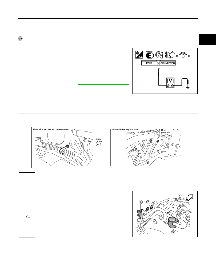
1. Disconnect EVAP control system pressure sensor (2) harness
connector.
-
Fuel filler pipe (top of frame view) (1)
-
EVAP canister vent control valve (3)
-
EVAP canister (4)
-
Drain filter (5)
-
: Vehicle front
2. Check sensor harness connector for water.
OK or NG
OK
>> GO TO 3.
NG
>> Repair or replace harness connector.
3.
CHECK EVAP CONTROL SYSTEM PRESSURE SENSOR
EC-788, "Component Inspection"
OK or NG
OK
>> GO TO 4.
NG
>> Replace EVAP control system pressure sensor. Refer to
FL-16, "Removal and Installation"
.
4.
CHECK INTERMITTENT INCIDENT
GI-37, "Intermittent Incident"
>>
INSPECTION END
Component Inspection
INFOID:0000000007358658
EVAP CONTROL SYSTEM PRESSURE SENSOR
1. Remove EVAP control system pressure sensor with its harness connector. Refer to
.
Always replace O-ring with a new one.
2. Install a vacuum pump to EVAP control system pressure sensor.
BBIA0539E
Water should not exist.
AWBIA0134ZZ
August 2012
2012 Pathfinder
P0451 EVAP CONTROL SYSTEM PRESSURE SENSOR
EC-789
< DTC/CIRCUIT DIAGNOSIS >
[VK56DE]
C
D
E
F
G
H
I
J
K
L
M
A
EC
N
P
O
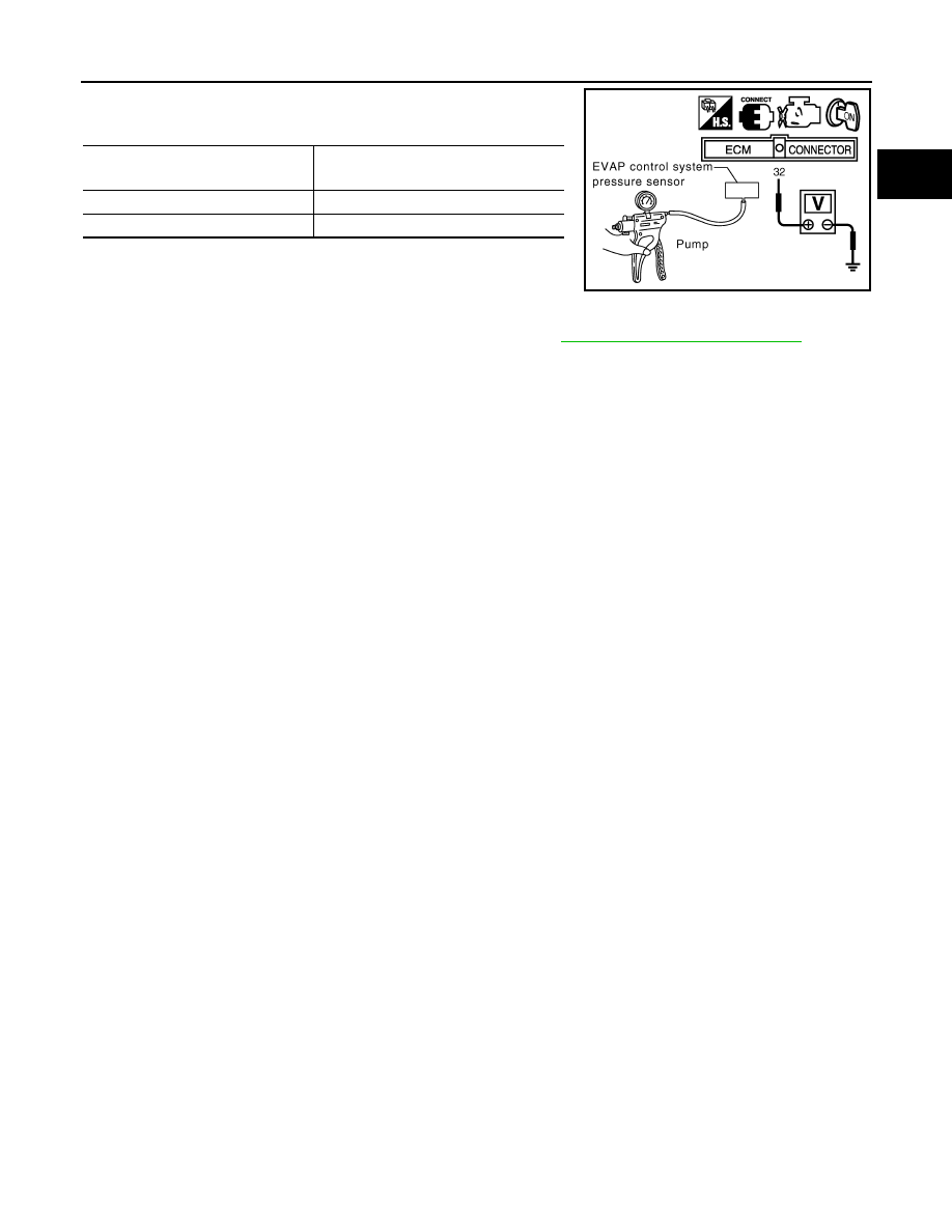
3. Turn ignition switch ON and check output voltage between ECM
terminal 32 and ground under the following conditions.
CAUTION:
• Always calibrate the vacuum pump gauge when using it.
• Never apply below -93.3 kPa (-0.952 kg/cm
2
, -13.53 psi) or
pressure over 101.3 kPa (1.033 kg/cm
2
, 14.69 psi).
4. If NG, replace EVAP control system pressure sensor. Refer to
FL-16, "Removal and Installation"
.
Applied vacuum
[kPa (kg/cm
2
, psi)]
Voltage
Not applied
1.8 - 4.8 V
-26.7 (-0.272, -3.87)
2.1 to 2.5 V lower than above value
PBIB1173E
August 2012
2012 Pathfinder
EC-790
< DTC/CIRCUIT DIAGNOSIS >
[VK56DE]
P0452 EVAP CONTROL SYSTEM PRESSURE SENSOR
P0452 EVAP CONTROL SYSTEM PRESSURE SENSOR
Component Description
INFOID:0000000007358659
The EVAP control system pressure sensor (2) detects pressure in
the purge line. The sensor output voltage to the ECM increases as
pressure increases.
• Fuel filler pipe (top of frame view) (1)
• EVAP canister vent control valve (3)
• EVAP canister (4)
• Drain filter (5)
•
: Vehicle front
On Board Diagnosis Logic
INFOID:0000000007358660
NOTE:
If DTC P0452 is displayed with DTC P0643, first perform the trouble diagnosis for DTC P0643. Refer to
EC-831, "DTC Confirmation Procedure"
.
DTC Confirmation Procedure
INFOID:0000000007358661
NOTE:
If DTC Confirmation Procedure has been previously conducted, always perform the following procedure
before conducting the next step.
1. Turn ignition switch OFF and wait at least 10 seconds.
2. Turn ignition switch ON.
3. Turn ignition switch OFF and wait at least 10 seconds.
TESTING CONDITION:
Always perform test at a temperature of 5
°
C (41
°
F) or more.
WITH CONSULT
1. Start engine and warm it up to normal operating temperature.
2. Turn ignition switch OFF and wait at least 10 seconds.
3. Turn ignition switch ON.
4. Turn ignition switch OFF and wait at least 10 seconds.
5. Turn ignition switch ON.
6. Select “DATA MONITOR” mode with CONSULT.
7. Check that “FUEL T/TMP SE” is more than 0
°
C (32
°
F).
AWBIA0134ZZ
PBIB3370E
DTC No.
Trouble diagnosis name
DTC detecting condition
Possible cause
P0452
0452
EVAP control system pressure
sensor low input
An excessively low voltage from the sensor
is sent to ECM.
• Harness or connectors
(The sensor circuit is open or shorted.)
• EVAP control system pressure sensor
August 2012
2012 Pathfinder
P0452 EVAP CONTROL SYSTEM PRESSURE SENSOR
EC-791
< DTC/CIRCUIT DIAGNOSIS >
[VK56DE]
C
D
E
F
G
H
I
J
K
L
M
A
EC
N
P
O
8. Start engine and wait at least 20 seconds.
9. Check 1st trip DTC.
10. If 1st trip DTC is detected, go to
WITH GST
1. Start engine and warm it up to normal operating temperature.
2. Check that voltage between ECM terminal 107 (Fuel tank tem-
perature sensor signal) and ground is less than 4.2V.
3. Turn ignition switch OFF and wait at least 10 seconds.
4. Turn ignition switch ON.
5. Turn ignition switch OFF and wait at least 10 seconds.
6. Start engine and wait at least 20 seconds.
7. Select Service $07 with GST.
If 1st trip DTC is detected, go to
Diagnosis Procedure
INFOID:0000000007358662
1.
CHECK GROUND CONNECTIONS
1. Turn ignition switch OFF.
2. Loosen and retighten ground screws on the body.
OK or NG
OK
>> GO TO 2.
NG
>> Repair or replace ground connections.
2.
CHECK CONNECTOR
1. Disconnect EVAP control system pressure sensor (2) harness
connector.
-
Fuel filler pipe (top of frame view) (1)
-
EVAP canister vent control valve (3)
-
EVAP canister (4)
-
Drain filter (5)
-
: Vehicle front
2. Check sensor harness connector for water.
OK or NG
OK
>> GO TO 3.
NG
>> Repair or replace harness connector.
3.
CHECK EVAP CONTROL SYSTEM PRESSURE SENSOR POWER SUPPLY CIRCUIT
1. Turn ignition switch ON.
PBIB1110E
BBIA0539E
Water should not exist.
AWBIA0134ZZ
August 2012
2012 Pathfinder
EC-792
< DTC/CIRCUIT DIAGNOSIS >
[VK56DE]
P0452 EVAP CONTROL SYSTEM PRESSURE SENSOR
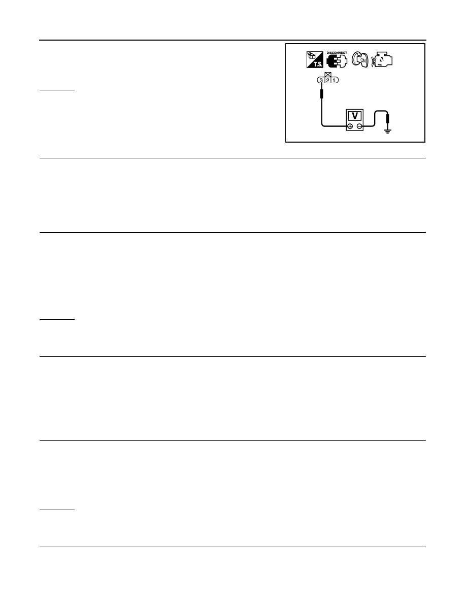
2. Check voltage between EVAP control system pressure sensor
terminal 3 and ground with CONSULT or tester.
OK or NG
OK
>> GO TO 5.
NG
>> GO TO 4.
4.
DETECT MALFUNCTIONING PART
Check the following.
• Harness connectors C1, E41
• Harness connectors E5, F14
• Harness for open or short between EVAP control system pressure sensor and ECM
>> Repair open circuit or short to ground or short to power in harness or connectors.
5.
CHECK EVAP CONTROL SYSTEM PRESSURE SENSOR GROUND CIRCUIT FOR OPEN AND SHORT
1. Turn ignition switch OFF.
2. Disconnect ECM harness connector.
3. Check harness continuity between EVAP control system pressure sensor terminal 1 and ECM terminal
67.
Refer to Wiring Diagram.
4. Also check harness for short to ground and short to power.
OK or NG
OK
>> GO TO 7.
NG
>> GO TO 6.
6.
DETECT MALFUNCTIONING PART
Check the following.
• Harness connectors C1, E41
• Harness connectors E5, F14
• Harness for open or short between EVAP control system pressure sensor and ECM
>> Repair open circuit or short to ground or short to power in harness or connectors.
7.
CHECK EVAP CONTROL SYSTEM PRESSURE SENSOR INPUT SIGNAL CIRCUIT FOR OPEN AND
SHORT
1. Check harness continuity between ECM terminal 32 and EVAP control system pressure sensor terminal
2.
Refer to Wiring Diagram.
2. Also check harness for short to ground and short to power.
OK or NG
OK
>> GO TO 9.
NG
>> GO TO 8.
8.
DETECT MALFUNCTIONING PART
Check the following.
• Harness connectors C1, E41
• Harness connectors E5, F14
Voltage: Approximately 5 V
PBIB0138E
Continuity should exist.
Continuity should exist.
August 2012
2012 Pathfinder
Нет комментариевНе стесняйтесь поделиться с нами вашим ценным мнением.
Текст