Nissan Pathfinder (2012 year). Instruction — part 197
FRONT OIL SEAL
DLN-141
< REMOVAL AND INSTALLATION >
[TRANSFER: ATX14B]
C
E
F
G
H
I
J
K
L
M
A
B
DLN
N
O
P
FRONT OIL SEAL
Removal and Installation
INFOID:0000000007357472
REMOVAL
1. Remove the front propeller shaft. Refer to
DLN-319, "Removal and Installation"
.
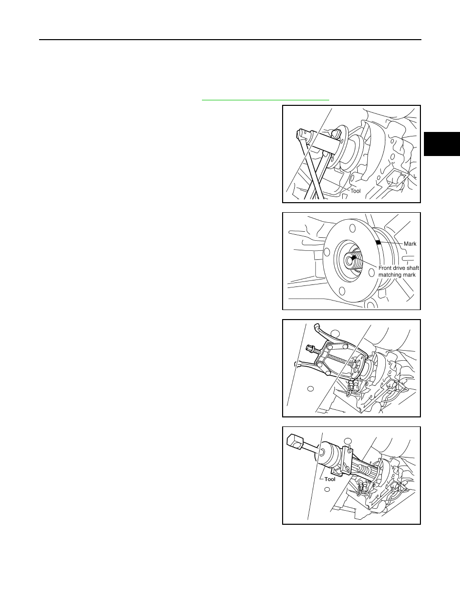
2. Remove the companion flange self-lock nut using suitable tool.
3. Put a matching mark on top of the front drive shaft in line with
the mark on the companion flange.
CAUTION:
Use paint to make the matching mark on the front drive
shaft. Do not damage the front drive shaft.
4. Remove the companion flange using suitable tool.
5. Remove the front oil seal from the front case using Tool.
CAUTION:
Do not damage front case.
INSTALLATION
SDIA2657E
SDIA2658E
WDIA0193E
Tool number
: ST33290001 (J-34286)
LDIA0144E
August 2012
2012 Pathfinder
DLN-142
< REMOVAL AND INSTALLATION >
[TRANSFER: ATX14B]
FRONT OIL SEAL
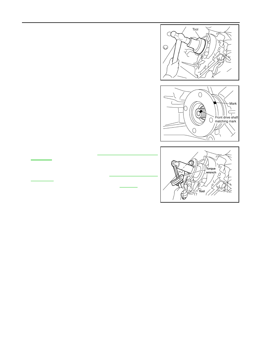
1. Install the new front oil seal until it is flush with the end face of
the front case using Tool.
CAUTION:
• Do not reuse oil seal.
• Apply petroleum jelly to oil seal.
2. Align the matching mark of the front drive shaft with the match-
ing mark of the companion flange, then install the companion
flange.
3. Install the new self-lock nut. Tighten to the specified torque
using suitable tool. Refer to
CAUTION:
Do not reuse self-lock nut.
4. Install the front propeller shaft. Refer to
.
5. Check for fluid leaks and fluid level. Refer to
Tool number
: KV38100500 ( — )
SDIA2662E
SDIA2658E
LDIA0147E
August 2012
2012 Pathfinder
REAR OIL SEAL
DLN-143
< REMOVAL AND INSTALLATION >
[TRANSFER: ATX14B]
C
E
F
G
H
I
J
K
L
M
A
B
DLN
N
O
P
REAR OIL SEAL
Removal and Installation
INFOID:0000000007357473
REMOVAL
1. Remove the rear propeller shaft. Refer to
DLN-329, "Removal and Installation"
(2S1330),
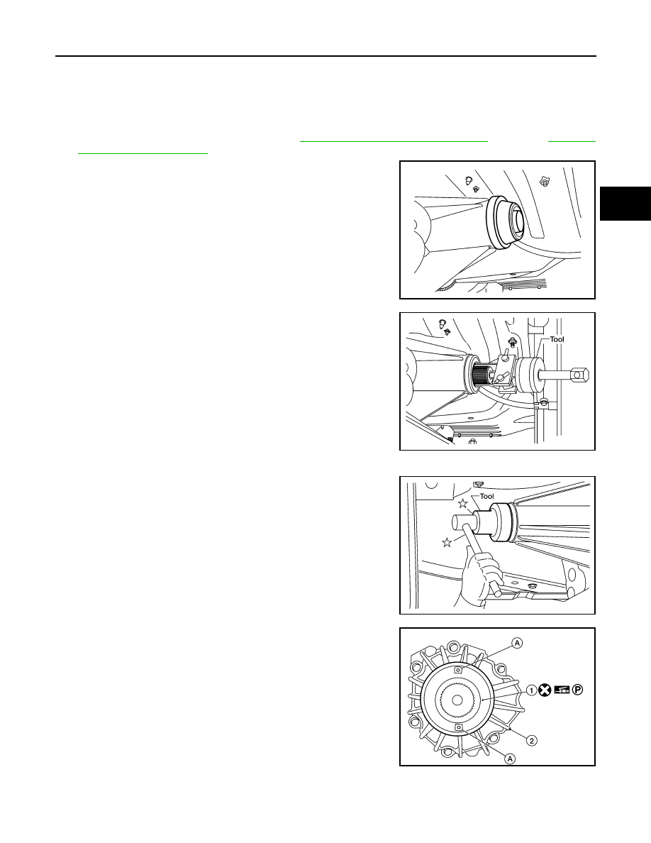
2. Remove the dust cover from the rear case.
CAUTION:
Do not damage the rear case.
3. Remove the rear oil seal from the rear case using Tool.
CAUTION:
Do not damage the rear case.
INSTALLATION
1. Install the new rear oil seal until it is flush with the end face of the
rear case using Tool.
CAUTION:
• Do not reuse oil seal.
• Apply petroleum jelly to oil seal.
2. Apply petroleum jelly to the circumference of the new dust cover.
Position the new dust cover as shown.
CAUTION:
• Do not reuse dust cover.
• Position the protrusions at the position shown.
• 1: Dust cover
• 2: Rear case assembly
• A: Protrusions
WDIA0127E
Tool number
: ST33290001 (J-34286)
LDIA0139E
Tool number
: ST30720000 (J-25405)
LDIA0140E
AWDIA0550GB
August 2012
2012 Pathfinder

DLN-144
< REMOVAL AND INSTALLATION >
[TRANSFER: ATX14B]
REAR OIL SEAL
3. Install the new dust cover to the rear case using Tool.
CAUTION:
• Do not reuse dust cover.
• Apply petroleum jelly to dust cover.
4. Install the rear propeller shaft. Refer to
(2S1330),
DLN-340, "Removal and Installation"
(2S1350).
5. Check for fluid leaks and fluid level. Refer to
Tool number
: KV40105310 ( — )
PDIA0116E
August 2012
2012 Pathfinder
SIDE OIL SEAL
DLN-145
< REMOVAL AND INSTALLATION >
[TRANSFER: ATX14B]
C
E
F
G
H
I
J
K
L
M
A
B
DLN
N
O
P
SIDE OIL SEAL
Removal and Installation
INFOID:0000000007357474
REMOVAL
1. Remove the front propeller shaft. Refer to
DLN-319, "Removal and Installation"
.
2. Remove the companion flange. Refer to
DLN-289, "Disassembly and Assembly"
.
3. Remove the transfer control device from the transfer assembly. Refer to
DLN-283, "Removal and Installa-
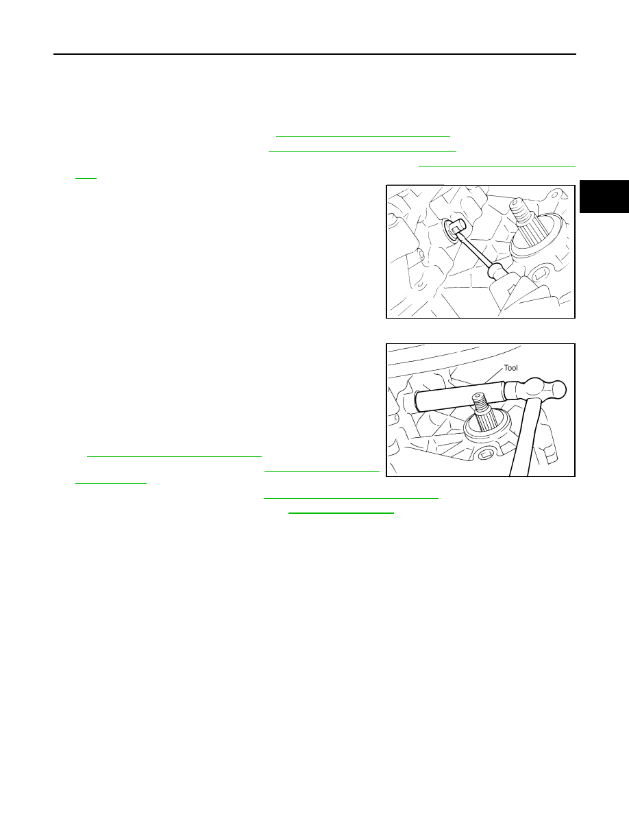
4. Remove the side oil seal using suitable tool.
CAUTION:
Do not damage shift cross.
INSTALLATION
1. Install the new side oil seal until it is flush with the end face of
case using Tool.
CAUTION:
• Do not reuse oil seal.
• Apply petroleum jelly to oil seal.
2. Install the transfer control device to the transfer assembly. Refer
DLN-283, "Removal and Installation"
3. Install the companion flange. Refer to
.
4. Install the front propeller shaft. Refer to
DLN-319, "Removal and Installation"
5. Check for fluid leaks and fluid level. Refer to
SDIA2666E
Tool number
: ST22360002 (J-25679-01)
SDIA2665E
August 2012
2012 Pathfinder
DLN-146
< REMOVAL AND INSTALLATION >
[TRANSFER: ATX14B]
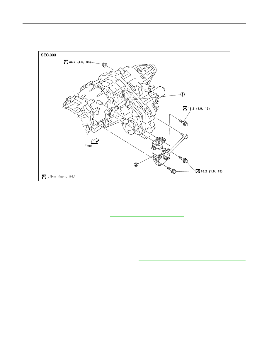
TRANSFER CONTROL DEVICE
TRANSFER CONTROL DEVICE
Removal and Installation
INFOID:0000000007357475
REMOVAL
CAUTION:
Change vehicle state to 2WD, and then remove and install transfer control device.
1. Remove front propeller shaft. Refer to
DLN-319, "Removal and Installation"
.
2. Disconnect transfer control device connector.
3. Remove transfer control lever.
4. Disconnect vacuum line.
5. Remove transfer control device.
INSTALLATION
CAUTION:
Check 4WD shift indicator after installation. Refer to
DLN-130, "Precaution for Transfer Assembly and
Transfer Control Unit Replacement"
Installation is in the reverse order of removal.
1.
Shift lever
2.
Actuator
SDIA2654E
August 2012
2012 Pathfinder
AIR BREATHER HOSE
DLN-147
< REMOVAL AND INSTALLATION >
[TRANSFER: ATX14B]
C
E
F
G
H
I
J
K
L
M
A
B
DLN
N
O
P
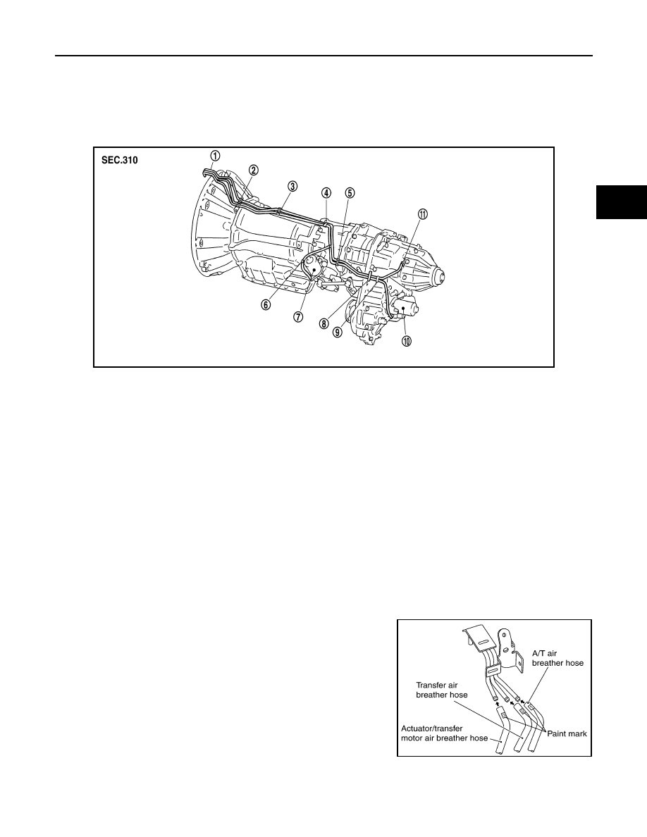
AIR BREATHER HOSE
Removal and Installation
INFOID:0000000007357476
COMPONENTS
VQ40DE
REMOVAL
1. Disconnect air breather hose from transfer motor.
2. Disconnect air breather hose from breather tube (transfer).
3. Disconnect air breather hose from actuator.
4. Release air breather hose clamp and clips as necessary.
5. Disconnect air breather hoses from breather tube.
CAUTION:
Note paint marks for installation.
INSTALLATION
CAUTION:
Make sure there are no pinched or restricted areas on each air breather hose caused by folding or
bending when installing it.
1. Install each air breather hose into the breather tube (metal con-
nector) until the hose end reaches the end of the curve section.
Set each air breather hose with paint mark facing upward.
SDIA3339E
1.
Breather tube
2.
Clip A
3.
Clip B
4.
Clip C
5.
Clip D
6.
Clip E
7.
Actuator
8.
Air breather hose clamp
9.
Clip F
10. Transfer motor
11. Breather tube (transfer)
SDIA3340E
August 2012
2012 Pathfinder
DLN-148
< REMOVAL AND INSTALLATION >
[TRANSFER: ATX14B]
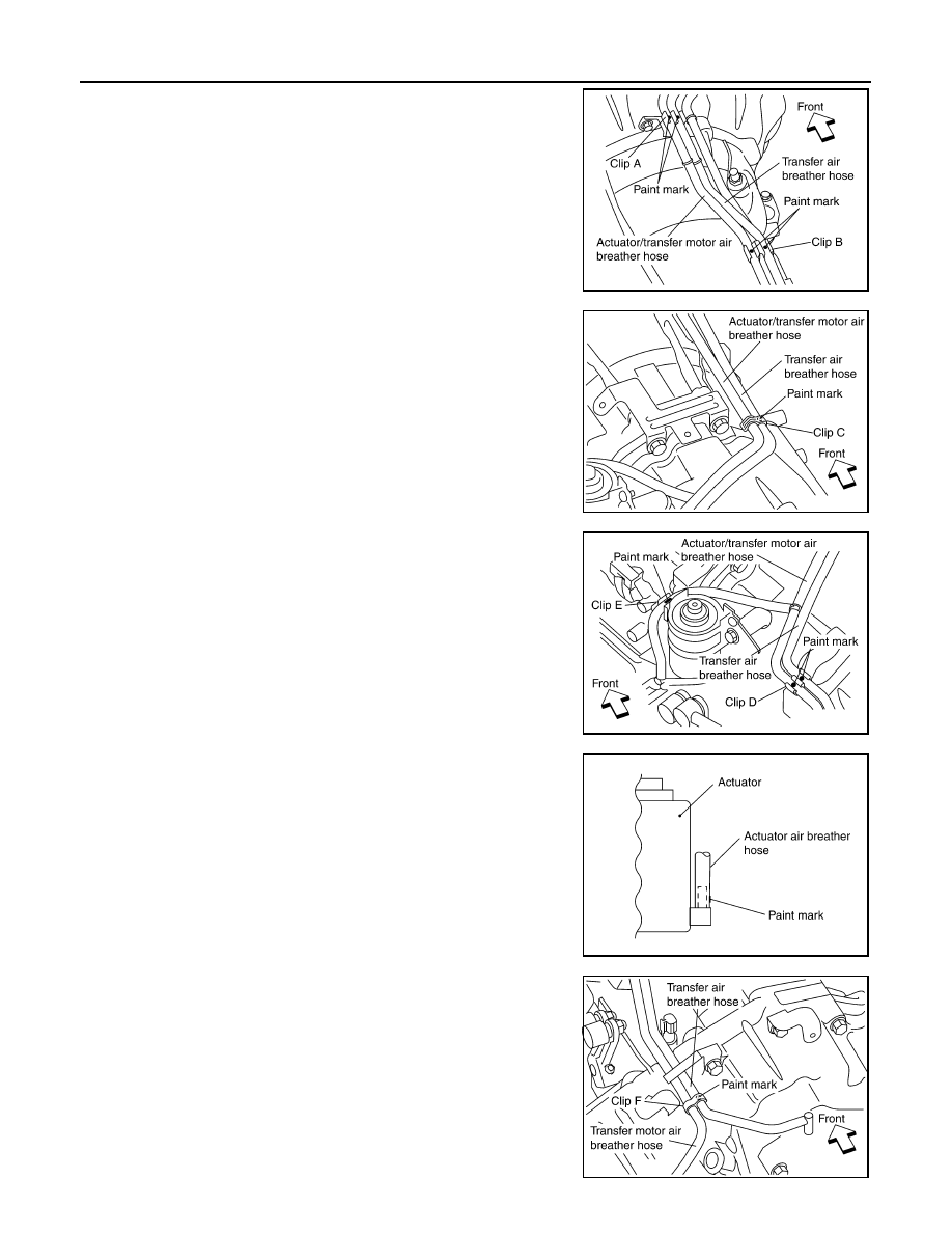
AIR BREATHER HOSE
2. Install actuator/transfer motor air breather hose and transfer air
breather hose on clip A with the paint mark facing upward.
3. Install clip C on actuator/transfer motor air breather hose and
transfer air breather hose with the paint mark matched.
4. Install actuator/transfer motor air breather hose and transfer air
breather hose on clip D and clip E with the paint mark facing
upward.
5. Install the actuator air breather hose into the actuator (case con-
nector) until the hose end reaches the base of the tube. Set
actuator air breather hose with paint mark facing leftward.
6. Install clip F on transfer motor air (control device) breather hose
and transfer air breather hose with the paint mark matched.
SDIA3342E
SDIA3343E
SDIA3344E
SDIA3226E
SDIA3345E
August 2012
2012 Pathfinder
Нет комментариевНе стесняйтесь поделиться с нами вашим ценным мнением.
Текст