Nissan Pathfinder (2012 year). Instruction — part 258
P0127 IAT SENSOR
EC-145
< DTC/CIRCUIT DIAGNOSIS >
[VQ40DE]
C
D
E
F
G
H
I
J
K
L
M
A
EC
N
P
O
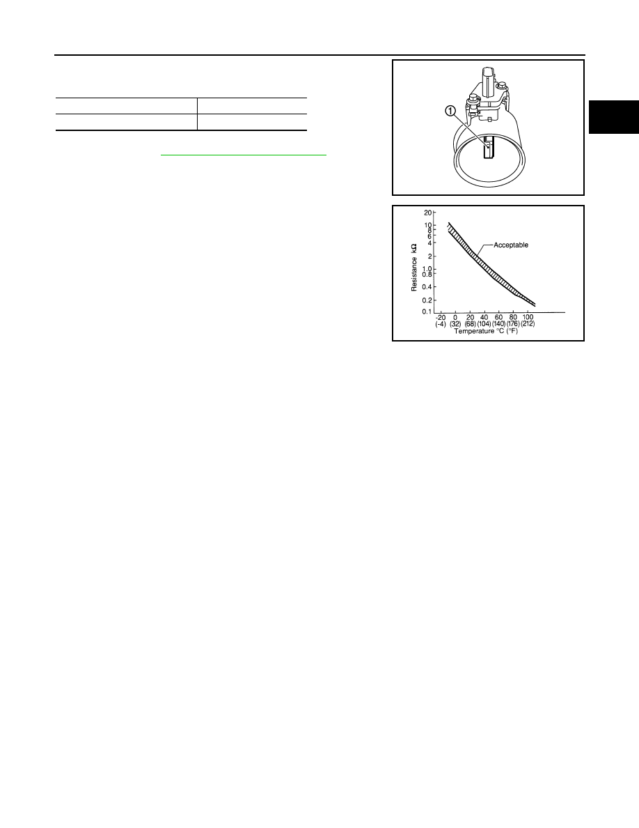
1. Check resistance between intake air temperature sensor (1) ter-
minals 5 and 6 under the following conditions.
2. If NG, replace mass air flow sensor (with intake air temperature
sensor). Refer to
EM-26, "Removal and Installation"
Intake air temperature
°
C (
°
F)
Resistance k
Ω
25 (77)
1.800 - 2.200
PBIA9559J
SEF012P
August 2012
2012 Pathfinder

EC-146
< DTC/CIRCUIT DIAGNOSIS >
[VQ40DE]
P0128 THERMOSTAT FUNCTION
P0128 THERMOSTAT FUNCTION
On Board Diagnosis Logic
INFOID:0000000007358062
NOTE:
If DTC P0128 is displayed with DTC P0300, P0301, P0302, P0303, P0304, P0305 or P0306, first perform
the trouble diagnosis for DTC P0300, P0301, P0302, P0303, P0304, P0305, P0306. Refer to
.
Engine coolant temperature has not risen enough to open the thermostat even though the engine has run long
enough.
This is due to a leak in the seal or the thermostat being stuck open.
DTC Confirmation Procedure
INFOID:0000000007358063
NOTE:
If DTC Confirmation Procedure has been previously conducted, always perform the following before conduct-
ing the next test.
1. Turn ignition switch OFF and wait at least 10 seconds.
2. Turn ignition switch ON.
3. Turn ignition switch OFF and wait at least 10 seconds.
WITH CONSULT
TESTING CONDITION:
•
For best results, perform at ambient temperature of –10
°
C (14
°
F) or higher.
•
For best results, perform at engine coolant temperature of –10
°
C (14
°
F) to 52
°
C (126
°
F).
•
Before performing the following procedure, do not add fuel.
1. Turn A/C switch OFF.
2. Turn blower fan switch OFF.
3. Turn ignition switch ON.
4. Select “COOLAN TEMP/S” in “DATA MONITOR” mode with CONSULT.
5. Check the indication of “COOLAN TEMP/S”.
If it is below 52
°
C (126
°
F), go to following step.
If it is above 52
°
C (126
°
F), cool down the engine to less than 52
°
C (126
°
F). Then go to next steps.
6. Start engine and wait at idle for at least 10 minutes under the following conditions.
CAUTION:
Always drive vehicle at a safe speed.
NOTE:
If “COOLAN TEMP/S” increases to more than 71
°
C (160
°
F) within 30 minutes, turn ignition switch
OFF because the test result will be OK.
7. Check 1st trip DTC.
8. If 1st trip DTC is detected, go to
WITH GST
Follow the procedure “WITH CONSULT” above.
Diagnosis Procedure
INFOID:0000000007358064
1.
CHECK ENGINE COOLANT TEMPERATURE SENSOR
EC-147, "Component Inspection"
OK or NG
DTC No.
Trouble diagnosis name
DTC detecting condition
Possible cause
P0128
0128
Thermostat function
The engine coolant temperature does not
reach to specified temperature even though
the engine has run long enough.
• Thermostat
• Leakage from sealing portion of thermostat
• Engine coolant temperature sensor
VHCL SPEED SE
More than 56 km/h (35MPH)
August 2012
2012 Pathfinder
P0128 THERMOSTAT FUNCTION
EC-147
< DTC/CIRCUIT DIAGNOSIS >
[VQ40DE]
C
D
E
F
G
H
I
J
K
L
M
A
EC
N
P
O
OK
>> GO TO 2.
NG
>> Replace engine coolant temperature sensor. Refer to
CO-30, "Removal and Installation"
2.
CHECK THERMOSTAT
CO-28, "Removal and Installation"
.
OK or NG
OK
>> INSPECTION END
NG
>> Replace thermostat.
Component Inspection
INFOID:0000000007358065
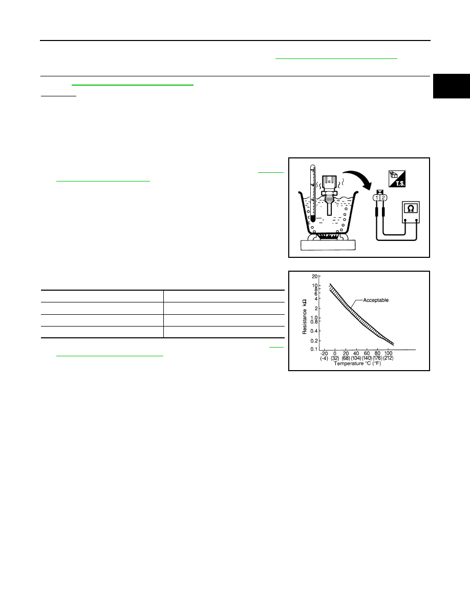
ENGINE COOLANT TEMPERATURE SENSOR
1. Check resistance between engine coolant temperature sensor
terminals 1 and 2 as shown in the figure. Refer to
<Reference data>
2. If NG, replace engine coolant temperature sensor. Refer to
30, "Removal and Installation"
PBIB2005E
Engine coolant temperature
°
C (
°
F)
Resistance k
Ω
20 (68)
2.1 - 2.9
50 (122)
0.68 - 1.00
90 (194)
0.236 - 0.260
SEF012P
August 2012
2012 Pathfinder
EC-148
< DTC/CIRCUIT DIAGNOSIS >
[VQ40DE]
P0130, P0150 A/F SENSOR 1
P0130, P0150 A/F SENSOR 1
Component Description
INFOID:0000000007358066
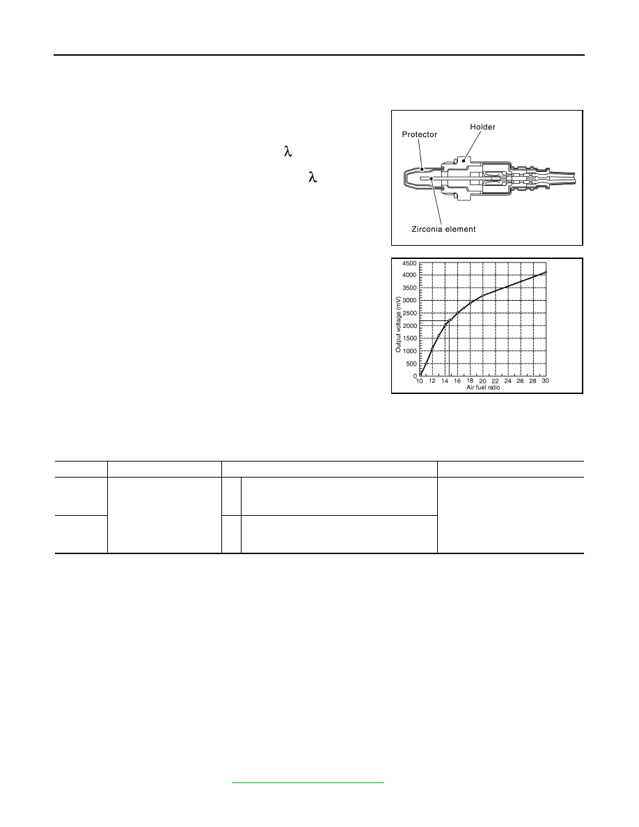
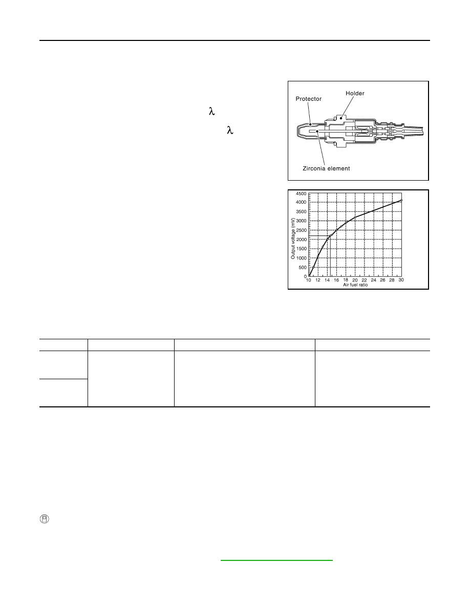
The air fuel ratio (A/F) sensor 1 is a planar one-cell limit current sen-
sor. The sensor element of the A/F sensor 1 is composed an elec-
trode layer, which transports ions. It has a heater in the element.
The sensor is capable of precise measurement = 1, but also in the
lean and rich range. Together with its control electronics, the sensor
outputs a clear, continuous signal throughout a wide range.
The exhaust gas components diffuse through the diffusion layer at
the sensor cell. An electrode layer is applied voltage, and this current
relative oxygen density in lean. Also this current relative hydrocar-
bon density in rich.
Therefore, the A/F sensor 1 is able to indicate air fuel ratio by this
electrode layer of current. In addition, a heater is integrated in the
sensor to ensure the required operating temperature of about 800
°
C
(1,472
°
F).
On Board Diagnosis Logic
INFOID:0000000007358067
To judge the malfunctions, the diagnosis checks that the A/F signal computed by ECM from the air fuel ratio
(A/F) sensor 1 signal fluctuates according to fuel feedback control.
DTC Confirmation Procedure
INFOID:0000000007358068
Perform PROCEDURE FOR MALFUNCTION A first.
If the DTC cannot be confirmed, perform PROCEDURE FOR MALFUNCTION B.
NOTE:
If DTC Confirmation Procedure has been previously conducted, always perform the following before conduct-
ing the next step.
1. Turn ignition switch OFF and wait at least 10 seconds.
2. Turn ignition switch ON.
3. Turn ignition switch OFF and wait at least 10 seconds.
TESTING CONDITION:
Before performing the following procedure, confirm that battery voltage is more than 11V at idle.
PROCEDURE FOR MALFUNCTION A
1. Start engine and warm it up to normal operating temperature.
2. Let engine idle for 2 minutes.
3. Check 1st trip DTC.
4. If 1st trip DTC is detected, go to
JPBIA4038GB
PBIB3354E
DTC No.
Trouble diagnosis name
DTC detecting condition
Possible Cause
P0130
0130
(Bank 1)
Air fuel ratio (A/F) sensor 1
circuit
A)
The A/F signal computed by ECM from the A/F
sensor 1 signal is constantly in a range other
than approx. 2.2V.
• Harness or connectors
(The A/F sensor 1 circuit is open
or shorted.)
• Air fuel ratio (A/F) sensor 1
P0150
0150
(Bank 2)
B)
The A/F signal computed by ECM from the A/F
sensor 1 signal is constantly approx. 2.2V.
August 2012
2012 Pathfinder

P0130, P0150 A/F SENSOR 1
EC-149
< DTC/CIRCUIT DIAGNOSIS >
[VQ40DE]
C
D
E
F
G
H
I
J
K
L
M
A
EC
N
P
O
PROCEDURE FOR MALFUNCTION B
CAUTION:
Always drive vehicle at a safe speed.
With CONSULT
1. Start engine and warm it up to normal operating temperature.
2. Select “A/F SEN1 (B1)” or “A/F SEN1 (B2)” in “DATA MONITOR” mode with CONSULT.
3. Check “A/F SEN1 (B1)” or “A/F SEN1 (B2)” indication.
If the indication is constantly approx. 2.2V and does not fluctuates, go to
.
If the indication fluctuate around 2.2V, go to next step.
4. Select “A/F SEN1 (B1) P1276” (for DTC P0130) or “A/F SEN1 (B2) P1286” (for DTC P0150) of “A/F
SEN1” in “DTC WORK SUPPORT” mode with CONSULT.
5. Touch “START”.
6. When the following conditions are met, “TESTING” will be displayed on the CONSULT screen.
If “TESTING” is not displayed after 20 seconds, retry from step 2.
7. Release accelerator pedal fully.
NOTE:
Never apply brake when releasing the accelerator pedal.
8. Make sure that “TESTING” changes to “COMPLETED”.
If “TESTING” changed to “OUT OF CONDITION”, retry from step 6.
9. Make sure that “OK” is displayed after touching “SELF-DIAG RESULT”.
If “NG” is displayed, go to
.
Overall Function Check
INFOID:0000000007358069
PROCEDURE FOR MALFUNCTION B
Use this procedure to check the overall function of the A/F sensor 1 circuit. During this check, a 1st trip DTC
might not be confirmed.
With GST
1. Start engine and warm it up to normal operating temperature.
2. Drive the vehicle at a speed of 80 km/h (50 MPH) for a few minutes in the suitable gear position.
3. Set D position with “OD” OFF, then release the accelerator pedal fully until the vehicle speed decreases to
50 km/h (30 MPH).
NOTE:
Never apply brake during releasing the accelerator pedal.
4. Repeat steps 2 and 3 for five times.
5. Stop the vehicle and turn ignition switch OFF.
6. Turn ignition switch ON.
7. Turn ignition switch OFF and wait at least 10 seconds.
8. Restart engine.
9. Repeat steps 2 and 3 for five times.
10. Stop the vehicle and connect GST to the vehicle.
11. Make sure that no 1st trip DTC is displayed.
If the 1st trip DTC is displayed, go to
.
Diagnosis Procedure
INFOID:0000000007358070
1.
CHECK GROUND CONNECTIONS
1. Turn ignition switch OFF.
ENG SPEED
1,100 - 3,200 rpm
VHCL SPEED SE
More than 64 km/h (40 MPH)
B/FUEL SCHDL
1.0 - 8.0 msec
Shift lever
D position with “OD” OFF
August 2012
2012 Pathfinder
EC-150
< DTC/CIRCUIT DIAGNOSIS >
[VQ40DE]
P0130, P0150 A/F SENSOR 1
2. Loosen and retighten three ground screws on the body. Refer to
OK or NG
OK
>> GO TO 2.
NG
>> Repair or replace ground connections.
2.
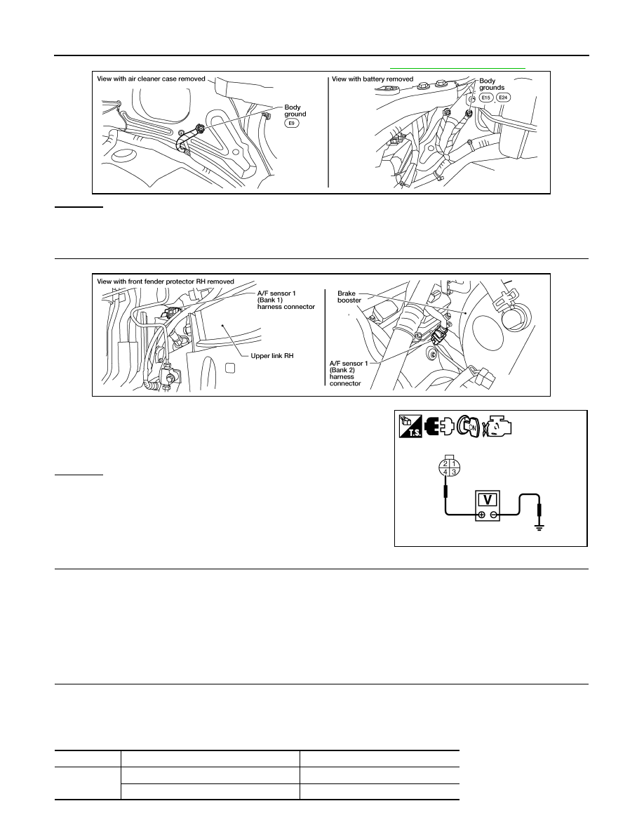
CHECK AIR FUEL RATIO (A/F) SENSOR 1 POWER SUPPLY CIRCUIT
1. Disconnect A/F sensor 1 harness connector.
2. Turn ignition switch ON.
3. Check voltage between A/F sensor 1 terminal 4 and ground with
CONSULT or tester.
OK or NG
OK
>> GO TO 4.
NG
>> GO TO 3.
3.
DETECT MALFUNCTIONING PART
Check the following.
• Harness connectors E2, F32
• IPDM E/R connector E119
• 15 A fuse (No.54)
• Harness for open or short between A/F sensor 1 and fuse
>> Repair or replace harness or connectors.
4.
CHECK A/F SENSOR 1 INPUT SIGNAL CIRCUIT FOR OPEN AND SHORT
1. Turn ignition switch OFF.
2. Disconnect ECM harness connector.
3. Check harness continuity between A/F sensor 1 terminal and ECM terminal as follows.
Refer to Wiring Diagram.
BBIA0539E
Voltage: Battery voltage
BBIA0544E
PBIB3308E
A/F sensor 1 terminal
ECM terminal
Bank 1
1
35
2
56
August 2012
2012 Pathfinder

P0130, P0150 A/F SENSOR 1
EC-151
< DTC/CIRCUIT DIAGNOSIS >
[VQ40DE]
C
D
E
F
G
H
I
J
K
L
M
A
EC
N
P
O
4. Check harness continuity between the following terminals and ground.
Refer to Wiring Diagram.
5. Also check harness for short to power.
OK or NG
OK
>> GO TO 5.
NG
>> Repair open circuit or short to ground or short to power in harness or connectors.
5.
CHECK INTERMITTENT INCIDENT
Perform
GI-37, "Intermittent Incident"
.
OK or NG
OK
>> GO TO 6.
NG
>> Repair or replace.
6.
REPLACE A/F SENSOR 1
Replace malfunctioning A/F sensor 1. Refer to
.
CAUTION:
• Discard any A/F sensor which has been dropped from a height of more than 0.5 m (19.7 in) onto a
hard surface such as a concrete floor; use a new one.
• Before installing new A/F sensor, clean exhaust system threads using Heated Oxygen Sensor
Thread Cleaner tool J-43897-18 or J-43897-12 and approved anti-seize lubricant.
>>
INSPECTION END
Bank 2
1
16
2
75
Continuity should exist.
Bank 1
Bank 2
A/F sensor 1 terminal
ECM terminal
A/F sensor 1 terminal
ECM terminal
1
35
1
16
2
56
2
75
Continuity should not exist.
August 2012
2012 Pathfinder
EC-152
< DTC/CIRCUIT DIAGNOSIS >
[VQ40DE]
P0131, P0151 A/F SENSOR 1
P0131, P0151 A/F SENSOR 1
Component Description
INFOID:0000000007358071
The air fuel ratio (A/F) sensor 1 is a planar one-cell limit current sen-
sor. The sensor element of the A/F sensor 1 is composed an elec-
trode layer, which transports ions. It has a heater in the element.
The sensor is capable of precise measurement = 1, but also in the
lean and rich range. Together with its control electronics, the sensor
outputs a clear, continuous signal throughout a wide range.
The exhaust gas components diffuse through the diffusion layer at
the sensor cell. An electrode layer is applied voltage, and this current
relative oxygen density in lean. Also this current relative hydrocar-
bon density in rich.
Therefore, the A/F sensor 1 is able to indicate air fuel ratio by this
electrode layer of current. In addition, a heater is integrated in the
sensor to ensure the required operating temperature of about 800
°
C
(1,472
°
F).
On Board Diagnosis Logic
INFOID:0000000007358072
To judge the malfunction, the diagnosis checks that the A/F signal computed by ECM from the air fuel ratio (A/
F) sensor 1 signal is not inordinately low.
DTC Confirmation Procedure
INFOID:0000000007358073
NOTE:
If DTC Confirmation Procedure has been previously conducted, always perform the following before conduct-
ing the next step.
1. Turn ignition switch OFF and wait at least 10 seconds.
2. Turn ignition switch ON.
3. Turn ignition switch OFF and wait at least 10 seconds.
TESTING CONDITION:
Before performing the following procedure, confirm that battery voltage is more than 11V at idle.
WITH CONSULT
1. Start engine and warm it up to normal operating temperature.
2. Select “A/F SEN1 (B1)” or “A/F SEN1 (B2)” in “DATA MONITOR” mode with CONSULT.
3. Check “A/F SEN1 (B1)” or “A/F SEN1 (B2)” indication.
If the indication is constantly approx. 0V, go to
If the indication is not constantly approx. 0V, go to next step.
4. Turn ignition switch OFF and wait at least 10 seconds.
JPBIA4038GB
PBIB3354E
DTC No.
Trouble diagnosis name
DTC detecting condition
Possible Cause
P0131
0131
(Bank 1)
Air fuel ratio (A/F) sensor 1
circuit low voltage
• The A/F signal computed by ECM from the A/
F sensor 1 signal is constantly approx. 0V.
• Harness or connectors
(The A/F sensor 1 circuit is open or
shorted.)
• A/F sensor 1
P0151
0151
(Bank 2)
August 2012
2012 Pathfinder
Нет комментариевНе стесняйтесь поделиться с нами вашим ценным мнением.
Текст