Nissan Pathfinder (2012 year). Instruction — part 137
REAR WINDOW DEFOGGER DOES NOT OPERATE BUT BOTH OF DOOR MIR-
ROR DEFOGGER OPERATE.
DEF-37
< SYMPTOM DIAGNOSIS >
C
D
E
F
G
H
I
J
K
M
A
B
DEF
N
O
P
REAR WINDOW DEFOGGER DOES NOT OPERATE BUT BOTH OF DOOR
MIRROR DEFOGGER OPERATE.
Diagnosis Procedure
INFOID:0000000007355342
1.
CHECK REAR WINDOW DEFOGGER POWER SUPPLY AND GROUND CIRCUIT
Check rear window defogger power supply and ground circuit.
DEF-12, "Component Function Check"
Is the inspection result normal?
YES
>> Refer to
GI-37, "Intermittent Incident"
.
NO
>> Repair or replace the malfunctioning parts.
August 2012
2012 Pathfinder
DEF-38
< SYMPTOM DIAGNOSIS >
BOTH DOORS MIRROR DEFOGGER DON’T OPERATE BUT REAR WINDOW
DEFOGGER OPERATES
BOTH DOORS MIRROR DEFOGGER DON’T OPERATE BUT REAR WIN-
DOW DEFOGGER OPERATES
Diagnosis Procedure
INFOID:0000000007355343
Regarding Wiring Diagram information, refer to
.
1.
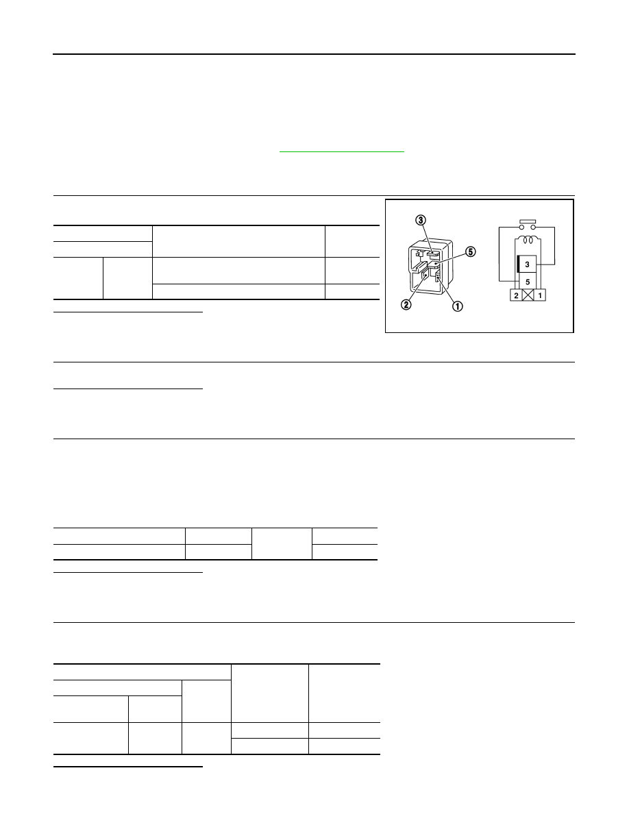
CHECK HEATED MIRROR RELAY
Check heated mirror relay.
Is the inspection result normal?
YES
>> GO TO 2
NO
>> Replace heated mirror relay.
2.
CHECK DOOR MIRROR DEFORGGER FUSE
Check fuse 43 (15A) in IPDM E/R.
Is the inspection result normal?
YES
>> GO TO 4
NO
>> GO TO 3
3.
CHECK DOOR MIRROR DEFORGGER POWER SUPPLY CIRCUIT FOR A SHORT
1. Turn ignition switch OFF.
2. Disconnect the following harness connectors.
-
IPDM E/R connector E120
-
Door mirror LH
-
Door mirror RH
3. Check continuity between IPDM E/R harness connector E120 terminal 23 and ground.
Is the inspection result normal?
YES
>> Replace fuse 43 (15A).
NO
>> Repair or replace harness.
4.
CHECK DOOR MIRROR DEFORGGER POWER SUPPLY CIRCUIT
1. Turn ignition switch ON.
2. Check voltage between IPDM E/R harness connector E120 terminal 23 and ground.
Is the inspection result normal?
YES
>> GO TO 5
Terminal
Condition
Continuity
Heated mirror relay
3
5
12V direct current supply between termi-
nals 1 and 2.
Yes
No current supply
No
SEF497Y
IPDM E/R connector
Terminal
Ground
Continuity
E120
23
No
Terminals
Condition of rear
window defogger
switch
Voltage (V)
(Approx.)
(+)
(–)
IPDM E/R con-
nector
Terminal
E120
23
Ground
ON
Battery voltage
OFF
0
August 2012
2012 Pathfinder

BOTH DOORS MIRROR DEFOGGER DON’T OPERATE BUT REAR WINDOW
DEFOGGER OPERATES
DEF-39
< SYMPTOM DIAGNOSIS >
C
D
E
F
G
H
I
J
K
M
A
B
DEF
N
O
P
NO
>> Replace IPDM E/R. Refer to
PCS-29, "Removal and Installation of IPDM E/R"
.
5.
CHECK DOOR MIRROR DEFOGGER
1. Check door mirror LH. Refer to
2. Check door mirror RH. Refer to
.
Is the inspection result normal?
YES
>> Check intermittent incident. Refer to
GI-37, "Intermittent Incident"
.
NO
>> Repair or replace the malfunctioning parts.
August 2012
2012 Pathfinder

DEF-40
< SYMPTOM DIAGNOSIS >
DRIVER SIDE DOOR MIRROR DEFOGGER DOES NOT OPERATE.
DRIVER SIDE DOOR MIRROR DEFOGGER DOES NOT OPERATE.
Diagnosis Procedure
INFOID:0000000007355344
1.
CHECK DOOR MIRROR DEFOGGER LH
Check door mirror defogger LH.
DEF-14, "Component Function Check"
Is the inspection result normal?
YES
>> Refer to
GI-37, "Intermittent Incident"
.
NO
>> Repair or replace the malfunctioning parts.
August 2012
2012 Pathfinder
PASSENGER SIDE DOOR MIRROR DEFOGGER DOES NOT OPERATE.
DEF-41
< SYMPTOM DIAGNOSIS >
C
D
E
F
G
H
I
J
K
M
A
B
DEF
N
O
P
PASSENGER SIDE DOOR MIRROR DEFOGGER DOES NOT OPERATE.
Diagnosis Procedure
INFOID:0000000007355345
1.
CHECK DOOR MIRROR DEFOGGER RH
Check door mirror defogger RH.
DEF-17, "Component Function Check"
Is the inspection result normal?
YES
>> Refer to
GI-37, "Intermittent Incident"
.
NO
>> Repair or replace the malfunctioning parts.
August 2012
2012 Pathfinder

DEF-42
< SYMPTOM DIAGNOSIS >
REAR WINDOW DEFOGGER SWITCH DOES NOT LIGHT, BUT REAR WINDOW
DEFOGGER OPERATES
REAR WINDOW DEFOGGER SWITCH DOES NOT LIGHT, BUT REAR WIN-
DOW DEFOGGER OPERATES
Diagnosis Procedure
INFOID:0000000007355346
1.
CHECK REAR WINDOW DEFOGGER SWITCH
Check that the rear window defogger switch is operating normally.
Is the inspection result normal?
YES
>> Refer to
GI-37, "Intermittent Incident"
.
NO
>> Refer to
DEF-8, "Diagnosis Procedure A/C and AV Switch Assembly"
August 2012
2012 Pathfinder
PRECAUTIONS
DEF-43
< PRECAUTION >
C
D
E
F
G
H
I
J
K
M
A
B
DEF
N
O
P
PRECAUTION
PRECAUTIONS
Precaution for Supplemental Restraint System (SRS) "AIR BAG" and "SEAT BELT
PRE-TENSIONER"
INFOID:0000000007355347
The Supplemental Restraint System such as “AIR BAG” and “SEAT BELT PRE-TENSIONER”, used along
with a front seat belt, helps to reduce the risk or severity of injury to the driver and front passenger for certain
types of collision. This system includes seat belt switch inputs and dual stage front air bag modules. The SRS
system uses the seat belt switches to determine the front air bag deployment, and may only deploy one front
air bag, depending on the severity of a collision and whether the front occupants are belted or unbelted.
Information necessary to service the system safely is included in the SR and SB section of this Service Man-
ual.
WARNING:
• To avoid rendering the SRS inoperative, which could increase the risk of personal injury or death in
the event of a collision which would result in air bag inflation, all maintenance must be performed by
an authorized NISSAN/INFINITI dealer.
• Improper maintenance, including incorrect removal and installation of the SRS, can lead to personal
injury caused by unintentional activation of the system. For removal of Spiral Cable and Air Bag
Module, see the SR section.
• Do not use electrical test equipment on any circuit related to the SRS unless instructed to in this
Instruction. SRS wiring harnesses can be identified by yellow and/or orange harnesses or har-
ness connectors.
PRECAUTIONS WHEN USING POWER TOOLS (AIR OR ELECTRIC) AND HAMMERS
WARNING:
• When working near the Airbag Diagnosis Sensor Unit or other Airbag System sensors with the Igni-
tion ON or engine running, DO NOT use air or electric power tools or strike near the sensor(s) with a
hammer. Heavy vibration could activate the sensor(s) and deploy the air bag(s), possibly causing
serious injury.
• When using air or electric power tools or hammers, always switch the Ignition OFF, disconnect the
battery, and wait at least 3 minutes before performing any service.
Precaution Necessary for Steering Wheel Rotation After Battery Disconnect
INFOID:0000000007355348
NOTE:
• This Procedure is applied only to models with Intelligent Key system and NATS (NISSAN ANTI-THEFT SYS-
TEM).
• Remove and install all control units after disconnecting both battery cables with the ignition knob in the
″
LOCK
″
position.
• Always use CONSULT to perform self-diagnosis as a part of each function inspection after finishing work. If
DTC is detected, perform trouble diagnosis according to self-diagnostic results.
For models equipped with the Intelligent Key system and NATS, an electrically controlled steering lock mech-
anism is adopted on the key cylinder.
For this reason, if the battery is disconnected or if the battery is discharged, the steering wheel will lock and
steering wheel rotation will become impossible.
If steering wheel rotation is required when battery power is interrupted, follow the procedure below before
starting the repair operation.
OPERATION PROCEDURE
1. Connect both battery cables.
NOTE:
Supply power using jumper cables if battery is discharged.
2. Use the Intelligent Key or mechanical key to turn the ignition switch to the
″
ACC
″
position. At this time, the
steering lock will be released.
3. Disconnect both battery cables. The steering lock will remain released and the steering wheel can be
rotated.
4. Perform the necessary repair operation.
August 2012
2012 Pathfinder
DEF-44
< PRECAUTION >
PRECAUTIONS
5. When the repair work is completed, return the ignition switch to the
″
LOCK
″
position before connecting
the battery cables. (At this time, the steering lock mechanism will engage.)
6. Perform a self-diagnosis check of all control units using CONSULT.
Handling for Adhesive and Primer
INFOID:0000000007355349
• Do not use an adhesive which is past its usable date. Shelf life of this product is limited to six months after
the date of manufacture. Carefully adhere to the expiration or manufacture date printed on the box.
• Keep primers and adhesive in a cool, dry place. Ideally, they should be stored in a refrigerator.
• Open the seal of the primer and adhesive just before application. Discard the remainder.
• Before application, be sure to shake the primer container to stir the contents. If any floating material is found,
do not use it.
• If any primer or adhesive contacts the skin, wipe it off with gasoline or equivalent and wash the skin with
soap.
• When using primer and adhesive, always observe the precautions in the instruction instruction.
August 2012
2012 Pathfinder
Нет комментариевНе стесняйтесь поделиться с нами вашим ценным мнением.
Текст