Nissan Pathfinder (2012 year). Instruction — part 151
INTELLIGENT KEY BATTERY AND FUNCTION
DLK-103
< DTC/CIRCUIT DIAGNOSIS >
[WITH INTELLIGENT KEY SYSTEM]
C
D
E
F
G
H
I
J
L
M
A
B
DLK
N
O
P
INTELLIGENT KEY BATTERY AND FUNCTION
Description
INFOID:0000000007355484
The following functions are available when having and carrying electronic ID.
• Door lock/unlock
• Back door open
Remote control entry function and panic alarm function are available when operating the remote buttons.
Component Function Check
INFOID:0000000007355485
NOTE:
The Signal Tech II Tool (J-50190) can be used to perform the following functions. Refer to the Signal Tech II
User Guide for additional information.
• Check Intelligent Key relative signal strength
• Confirm vehicle Intelligent Key antenna signal strength
1.
CHECK FUNCTION
With CONSULT
Check remote keyless entry receiver "I-KEY LOCK, I-KEY UNLOCK, I-KEY PANIC" in Data Monitor mode with
CONSULT.
Is the inspection result normal?
YES
>> Intelligent Key is OK.
NO
>> Refer to
DLK-103, "Diagnosis Procedure"
Diagnosis Procedure
INFOID:0000000007355486
NOTE:
The Signal Tech II Tool (J-50190) can be used to perform the following functions. Refer to the Signal Tech II
User Guide for additional information.
• Check Intelligent Key relative signal strength
• Confirm vehicle Intelligent Key antenna signal strength
1.
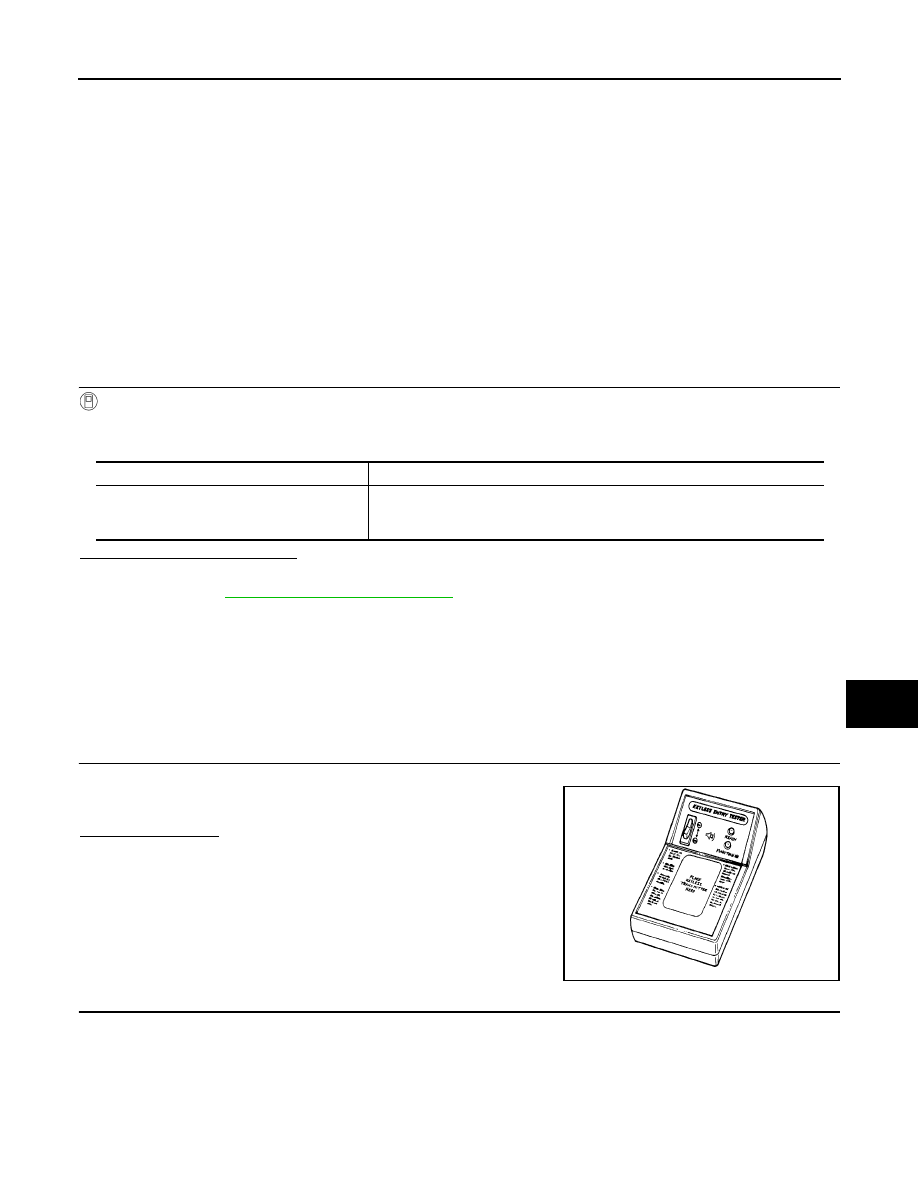
CHECK INTELLIGENT KEY FUNCTION
Check keyfob function using Signal Tech II Tool J-50190 or Remote
Keyless Entry Tester J-43241 (shown).
Does the test pass?
YES
>> Intelligent Key is OK.
NO
>> GO TO 2
2.
CHECK INTELLIGENT KEY COMPONENTS
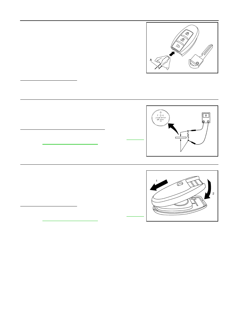
1. Release the lock knob at the back of the Intelligent Key and remove the mechanical key.
Monitor item
Condition
I-KEY LOCK
I-KEY UNLOCK
I-KEY PANIC
Checks whether value changes when operating Intelligent Key.
LEL946A
August 2012
2012 Pathfinder
2012 Pathfinder
DLK-104
< DTC/CIRCUIT DIAGNOSIS >
[WITH INTELLIGENT KEY SYSTEM]
INTELLIGENT KEY BATTERY AND FUNCTION
2. Insert a flat-blade screwdriver (A) wrapped with a cloth into the
slit of the corner and twist it to separate the upper part from the
lower part.
CAUTION:
• Do not touch the circuit board or battery terminal.
• The keyfob is water-resistant. However, if it does get wet,
immediately wipe it dry.
3. Remove the Intelligent Key battery.
CAUTION:
• Keep dirt, grease, and other foreign materials off the elec-
trode contact area.
4. Visually inspect keyfob internal components.
Is the inspection result normal?
YES
>> GO TO 3
NO
>> Repair or replace malfunctioning parts.
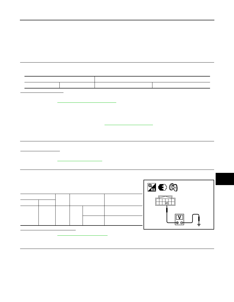
3.
CHECK INTELLIGENT KEY BATTERY
Check by connecting a resistance (approximately 300
Ω
) so that the
current value becomes about 10 mA.
Is the measurement value within specification?
YES
>> Intelligent Key battery is OK. Check remote keyless
entry receiver. Refer to
.
NO
>> GO TO 4
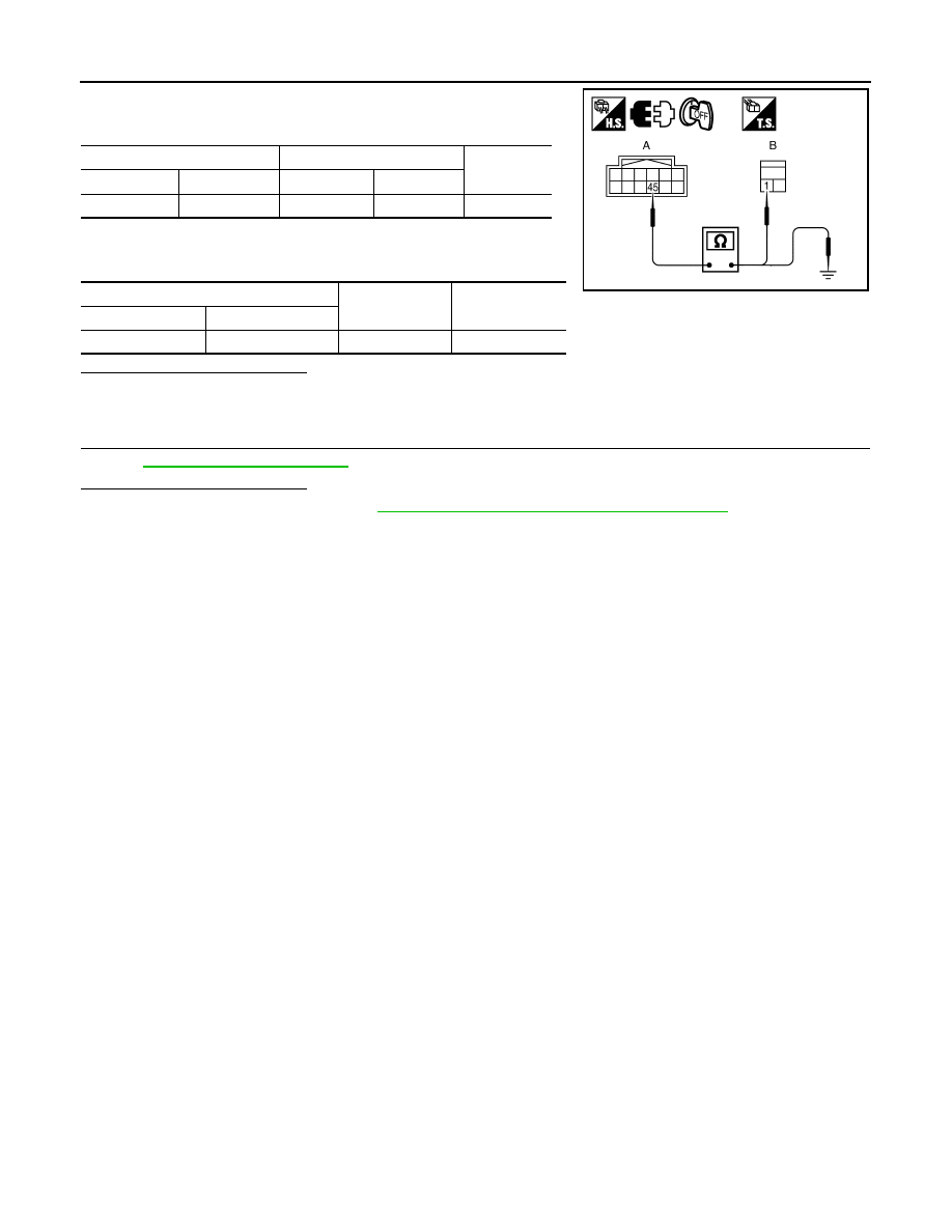
4.
REPLACE INTELLIGENT KEY BATTERY
1. Replace the Intelligent Key battery.
2. Align the tips of the upper and lower parts, and then push them
together until it is securely closed.
CAUTION:
• When replacing battery, keep dirt, grease, and other for-
eign materials off the electrode contact area.
3. After replacing the battery, check that all Intelligent Key func-
tions work properly.
Is the inspection result normal?
YES
>> Intelligent Key is OK.
NO
>> Check remote keyless entry receiver. Refer to
.
ALKIA1707ZZ
Standard
: Approx. 2.5 - 3.0V
OCC0607D
PIIB6222E
August 2012
2012 Pathfinder
2012 Pathfinder
HORN FUNCTION
DLK-105
< DTC/CIRCUIT DIAGNOSIS >
[WITH INTELLIGENT KEY SYSTEM]
C
D
E
F
G
H
I
J
L
M
A
B
DLK
N
O
P
HORN FUNCTION
Description
INFOID:0000000007355487
Perform answer-back for each operation with horn.
Component Function Check
INFOID:0000000007355488
1.
CHECK FUNCTION
1. Select "HORN" in “ACTIVE TEST” mode with CONSULT.
2. Check the horn (high/low) operation.
Is the operation normal?
YES
>> Inspection End.
NO
>> Refer to
DLK-105, "Diagnosis Procedure"
.
Diagnosis Procedure
INFOID:0000000007355489
Regarding Wiring Diagram information, refer to
.
1.
CHECK HORN FUNCTION
Check horn function with horn switch.
Does the horn sound?
YES
>> GO TO 2.
NO
>> Refer to
.
2.
CHECK HORN RELAY POWER SUPPLY
1. Turn ignition switch ON.
2. Perform “ACTIVE TEST”, "HORN" with CONSULT.
3. Using an oscilloscope or analog voltmeter, check voltage
between IPDM E/R connector E122 terminal 45 and ground.
Is the inspection result normal?
YES
>> Refer to
GI-37, "Intermittent Incident"
.
NO
>> GO TO 3
3.
CHECK HORN RELAY CIRCUIT
1. Turn ignition switch OFF.
2. Disconnect IPDM E/R and horn relay connector.
Test item
Description
HORN
ON
Horn relay
ON (for 20 ms)
IPDM E/R
Ground
Test item
Voltage (V)
(Approx.)
Connector
Terminal
E122
45
Ground HORN
OFF
→
ON
→
OFF
Battery voltage
→
0
→
Battery voltage
Other than
above
Battery voltage
WIIA1251E
August 2012
2012 Pathfinder
2012 Pathfinder
DLK-106
< DTC/CIRCUIT DIAGNOSIS >
[WITH INTELLIGENT KEY SYSTEM]
HORN FUNCTION
3. Check continuity between IPDM E/R harness connector and
horn relay harness connector.
4. Check continuity between IPDM E/R harness connector and
ground.
Is the inspection result normal?
YES
>> GO TO 4
NO
>> Repair or replace harness.
4.
CHECK INTERMITTENT INCIDENT
GI-37, "Intermittent Incident"
Is the inspection result normal?
YES
>> Replace IPDM E/R. Refer to
PCS-29, "Removal and Installation of IPDM E/R"
.
NO
>> Repair or replace the malfunctioning part.
IPDM E/R
Horn relay
Continuity
Connector
Terminal
Connector
Terminal
A: E122
45
B: H-1
1
Yes
IPDM E/R
Ground
Continuity
Connector
Terminal
E122
45
Ground
No
WIIA1252E
August 2012
2012 Pathfinder
2012 Pathfinder

COMBINATION METER DISPLAY FUNCTION
DLK-107
< DTC/CIRCUIT DIAGNOSIS >
[WITH INTELLIGENT KEY SYSTEM]
C
D
E
F
G
H
I
J
L
M
A
B
DLK
N
O
P
COMBINATION METER DISPLAY FUNCTION
Description
INFOID:0000000007355490
Displays each operation method guide and warning for system malfunction.
Component Function Check
INFOID:0000000007355491
1.
CHECK FUNCTION
1. Turn ignition switch ON.
2. Using CONSULT, activate "P-SHIFT" and "KEY" warning lamp indicators in "ACTIVE TEST" mode.
Do the warning lamps illuminate?
YES
>> Combination meter warning lamp indicators are OK.
NO
>> Refer to
DLK-107, "Diagnosis Procedure"
Diagnosis Procedure
INFOID:0000000007355492
1.
CHECK COMBINATION METER
.
Is the inspection result normal?
YES
>> GO TO 2
NO
>> Check combination meter. Refer to
.
2.
CHECK INTERMITTENT INCIDENT
GI-37, "Intermittent Incident"
.
>> Inspection End.
August 2012
2012 Pathfinder
2012 Pathfinder

DLK-108
< DTC/CIRCUIT DIAGNOSIS >
[WITH INTELLIGENT KEY SYSTEM]
WARNING CHIME FUNCTION
WARNING CHIME FUNCTION
Description
INFOID:0000000007355493
Performs operation method guide and warning with buzzer.
Component Function Check
INFOID:0000000007355494
1.
CHECK FUNCTION
With CONSULT
1. Check the operation with "INSIDE BUZZER" in the Active Test.
2. Touch “TAKE OUT”, “KNOB”or “KEY” on screen.
Is the inspection result normal?
Yes
>> Warning buzzer into combination meter is OK.
No
>> Refer to
DLK-108, "Diagnosis Procedure"
.
Diagnosis Procedure
INFOID:0000000007355495
1.
CHECK METER BUZZER CIRCUIT
The inoperative warning chime is contained inside the combination meter. Replace combination meter. Refer
to
MWI-89, "Removal and Installation"
.
>> Inspection End.
August 2012
2012 Pathfinder
2012 Pathfinder

HAZARD FUNCTION
DLK-109
< DTC/CIRCUIT DIAGNOSIS >
[WITH INTELLIGENT KEY SYSTEM]
C
D
E
F
G
H
I
J
L
M
A
B
DLK
N
O
P
HAZARD FUNCTION
Description
INFOID:0000000007355496
Perform answer-back for each operation with number of blinks.
Component Function Check
INFOID:0000000007355497
1.
CHECK FUNCTION
Check hazard warning lamp "FLASHER" in ACTIVE TEST mode.
Is the inspection result normal?
YES
>> Hazard warning lamp circuit is OK.
NO
>> Refer to
DLK-109, "Diagnosis Procedure"
Diagnosis Procedure
INFOID:0000000007355498
1.
CHECK HAZARD SWITCH CIRCUIT
Operate the hazard lights by turning ON the hazard warning switch.
Do the lights operate normally?
YES
>> Replace the BCM. Refer to
BCS-53, "Removal and Installation"
NO
>> Repair or replace hazard warning switch circuit. Refer to
August 2012
2012 Pathfinder
2012 Pathfinder
DLK-110
< DTC/CIRCUIT DIAGNOSIS >
[WITH INTELLIGENT KEY SYSTEM]
KEY SWITCH (INTELLIGENT KEY UNIT INPUT)
KEY SWITCH (INTELLIGENT KEY UNIT INPUT)
Diagnosis Procedure
INFOID:0000000007355499
Regarding Wiring Diagram information, refer to
.
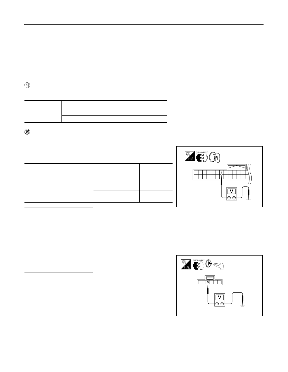
1.
CHECK KEY SWITCH
With CONSULT
Check key switch (“KEY SW”) in “DATA MONITOR” mode with CONSULT.
Without CONSULT
1. Turn ignition switch OFF.
2. Disconnect Intelligent Key unit harness connector.
3. Check voltage between Intelligent Key unit harness connector
M164 terminal 7 and ground.
Is the inspection result normal?
YES
>> Key switch is OK.
NO
>> GO TO 2
2.
CHECK KEY SWITCH POWER SUPPLY CIRCUIT
1. Remove mechanical key from ignition switch.
2. Disconnect key switch and ignition knob switch connector.
3. Check voltage between key switch and ignition knob switch harness connector M66 terminal 3 and
ground.
Is the inspection result normal?
YES
>> GO TO 3
NO
>> Repair or replace key switch and ignition knob switch
power supply circuit.
3.
CHECK KEY SWITCH OPERATION
Monitor item
Condition
KEY SW
Insert mechanical key into ignition switch: ON
Remove mechanical key from ignition switch: OFF
Connector
Terminals
Condition
Voltage (V)
(Approx.)
(+)
(–)
M164
7
Ground
Insert mechanical key
into ignition switch
Battery voltage
Remove mechanical
key from ignition switch
0
WIIA1173E
3 - Ground
: Battery voltage
ALKIA1213ZZ
August 2012
2012 Pathfinder
2012 Pathfinder
Нет комментариевНе стесняйтесь поделиться с нами вашим ценным мнением.
Текст