Nissan Pathfinder (2012 year). Instruction — part 75
AV-418
< PRECAUTION >
[BOSE AUDIO WITH NAVIGATION]
PRECAUTIONS
5. When the repair work is completed, return the ignition switch to the
″
LOCK
″
position before connecting
the battery cables. (At this time, the steering lock mechanism will engage.)
6. Perform a self-diagnosis check of all control units using CONSULT.
Precaution for Trouble Diagnosis
INFOID:0000000007347938
AV COMMUNICATION SYSTEM
• Do not apply voltage of 7.0 V or higher to the measurement terminals.
• Use the tester with its open terminal voltage being 7.0 V or less.
• Be sure to turn ignition switch OFF and disconnect the battery cable from the negative terminal before
checking the circuit.
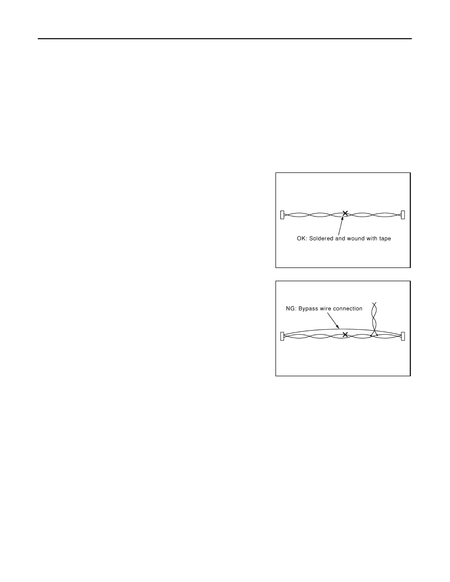
Precaution for Harness Repair
INFOID:0000000007347939
AV COMMUNICATION SYSTEM
• Solder the repaired parts, and wrap with tape. [Frays of twisted line
must be within 110 mm (4.33 in).]
• Do not perform bypass wire connections for the repair parts. (The
spliced wire will become separated and the characteristics of
twisted line will be lost.)
Precaution for Work
INFOID:0000000007347940
• When removing or disassembling each component, be careful not to damage or deform it. If a component
may be subject to interference, be sure to protect it with a shop cloth.
• When removing (disengaging) components with a screwdriver or similar tool, be sure to wrap the component
with a shop cloth or vinyl tape to protect it.
• Protect the removed parts with a shop cloth and prevent them from being dropped.
• Replace a deformed or damaged clip.
• If a part is specified as a non-reusable part, always replace it with new one.
• Be sure to tighten bolts and nuts securely to the specified torque.
• After installation is complete, be sure to check that each part works properly.
• Follow the steps below to clean components.
- Water soluble dirt: Dip a soft cloth into lukewarm water, and wring the water out of the cloth to wipe the dirty
area.
Then rub with a soft and dry cloth.
- Oily dirt: Dip a soft cloth into lukewarm water with mild detergent (concentration: within 2 to 3%), and wipe
the dirty area.
Then dip a cloth into fresh water, and wring the water out of the cloth to wipe the detergent off. Then rub with
a soft and dry cloth.
• Do not use organic solvent such as thinner, benzene, alcohol, or gasoline.
• For genuine leather seats, use a genuine leather seat cleaner.
PKIA0306E
PKIA0307E
August 2012
2012 Pathfinder
AV
PREPARATION
AV-419
< PREPARATION >
[BOSE AUDIO WITH NAVIGATION]
C
D
E
F
G
H
I
J
K
L
M
B
A
O
P
PREPARATION
PREPARATION
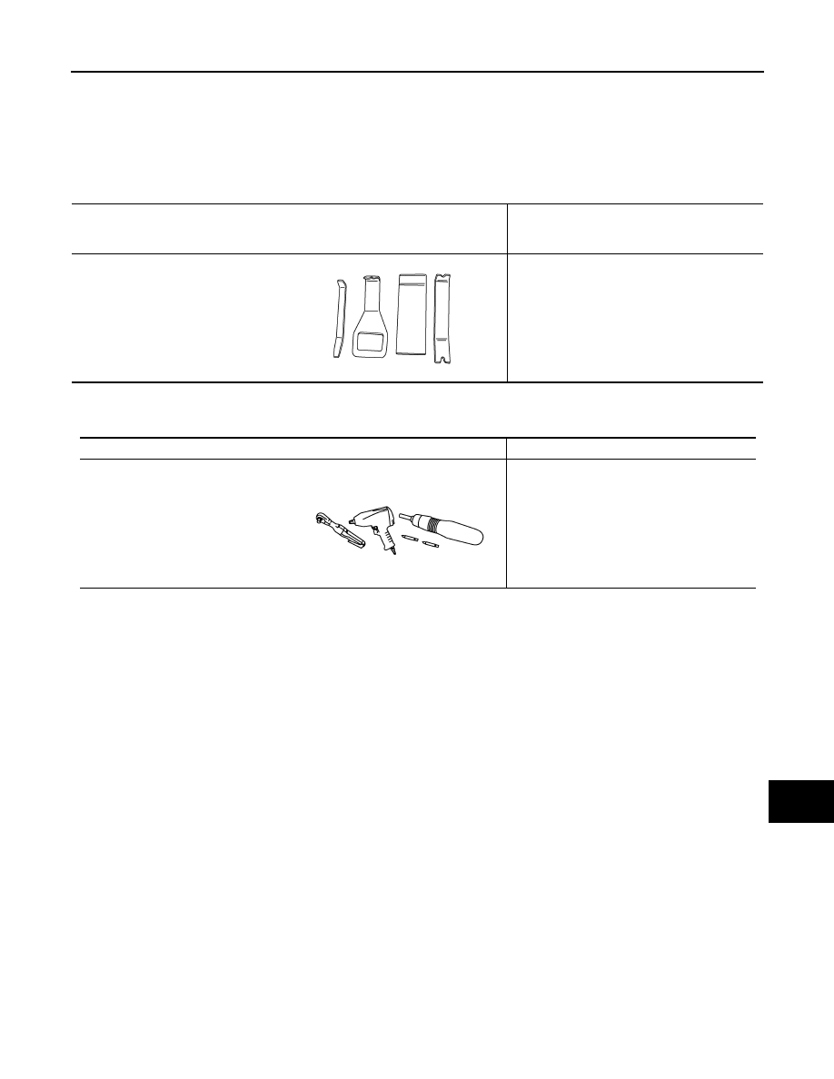
Special Service Tool
INFOID:0000000007347941
The actual shapes of Kent-Moore tools may differ from those of special service tools illustrated here.
Commercial Service Tools
INFOID:0000000007347942
Tool number
(Kent-Moore No.)
Tool name
Description
—
(J-46534)
Trim tool set
Removing trim components
AWJIA0483ZZ
Tool name
Description
Power tool
Loosening nuts, screws and bolts
PIIB1407E
August 2012
2012 Pathfinder
AV-420
< REMOVAL AND INSTALLATION >
[BOSE AUDIO WITH NAVIGATION]
AV CONTROL UNIT
REMOVAL AND INSTALLATION
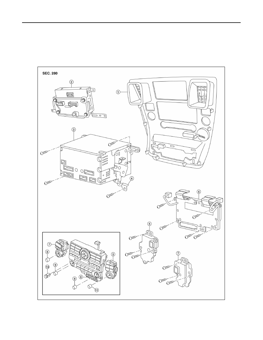
AV CONTROL UNIT
Removal and Installation
INFOID:0000000007347943
1.
Cluster lid C
2.
Display unit
3.
AV control unit
4.
AV control unit brackets
5.
Tuner knob switch
6.
A/C and AV switch assembly
7.
Volume knob switch
8.
Volume knob
9.
Temp knobs RH and LH
10. Enter button
11. Tuner knob
AWNIA2528ZZ
August 2012
2012 Pathfinder
AV
AV CONTROL UNIT
AV-421
< REMOVAL AND INSTALLATION >
[BOSE AUDIO WITH NAVIGATION]
C
D
E
F
G
H
I
J
K
L
M
B
A
O
P
CAUTION:
Only remove and replace the A/C or AV switch assembly knobs if damaged or missing. The knobs
must not be removed from switches when removing and installing the A/C or AV switch assembly to
prevent damage to the switch assembly.
REMOVAL
1. Disconnect the battery negative terminal.
2. Remove the cluster lid C. Refer to
IP-16, "Removal and Installation"
3. Remove the AV control unit screws, using a power tool.
4. Remove the AV control unit.
5. Remove the A/C and AV switch assembly screws, then remove the A/C and AV switch assemblies as nec-
essary.
INSTALLATION
Installation is in the reverse order of removal.
August 2012
2012 Pathfinder
AV-422
< REMOVAL AND INSTALLATION >
[BOSE AUDIO WITH NAVIGATION]
DISPLAY UNIT
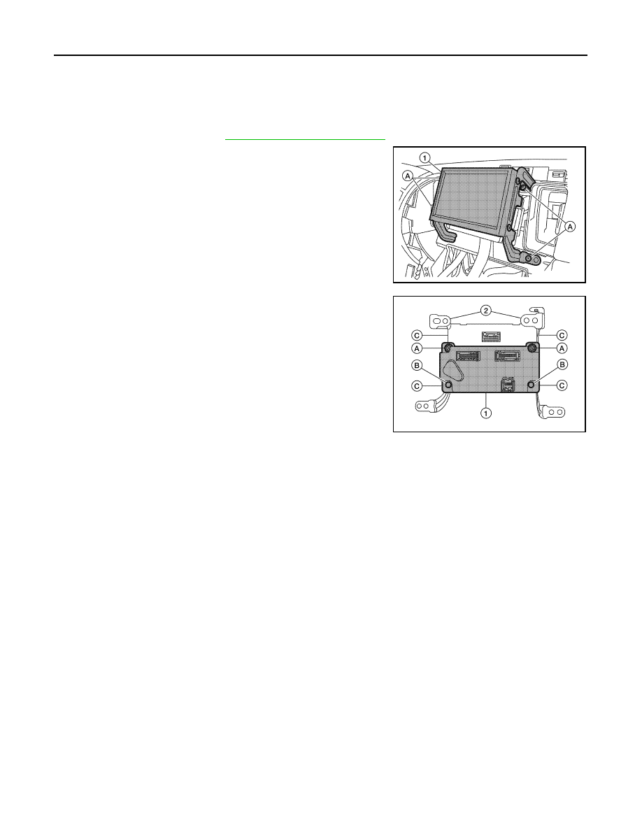
DISPLAY UNIT
Removal and Installation
INFOID:0000000007347944
REMOVAL
1. Remove cluster lid C. Refer to
IP-16, "Removal and Installation"
2. Remove the display unit screws (A).
3. Pull out the display unit (1), then disconnect the display unit con-
nectors and remove the display unit (1).
4. Remove the A/C auto amp.screws (A), remove the (C103) fas-
teners (B) from the display unit assembly brackets and remove
the A/C auto amp. (1).
5. Remove the display unit bracket unit screws (C) and remove the
display unit brackets (2).
INSTALLATION
Installation is in reverse order of removal.
ALNIA0358ZZ
ALNIA0359ZZ
August 2012
2012 Pathfinder
AV
FRONT TWEETER
AV-423
< REMOVAL AND INSTALLATION >
[BOSE AUDIO WITH NAVIGATION]
C
D
E
F
G
H
I
J
K
L
M
B
A
O
P
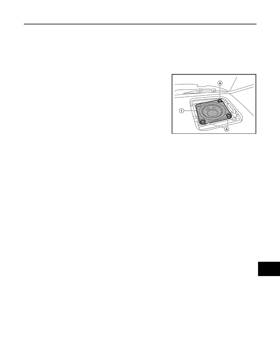
FRONT TWEETER
Removal and Installation
INFOID:0000000007347945
REMOVAL
CAUTION:
Use a suitable tool to prevent damage to the front tweeter speaker grille trim and the instrument panel.
1. Remove the front tweeter grille.
2. Remove the front tweeter screws (A).
3. Pull out the front tweeter speaker (1) and disconnect front
tweeter connector, then remove the front tweeter speaker (1).
INSTALLATION
Installation is in the reverse order of removal.
ALNIA0344ZZ
August 2012
2012 Pathfinder
AV-424
< REMOVAL AND INSTALLATION >
[BOSE AUDIO WITH NAVIGATION]
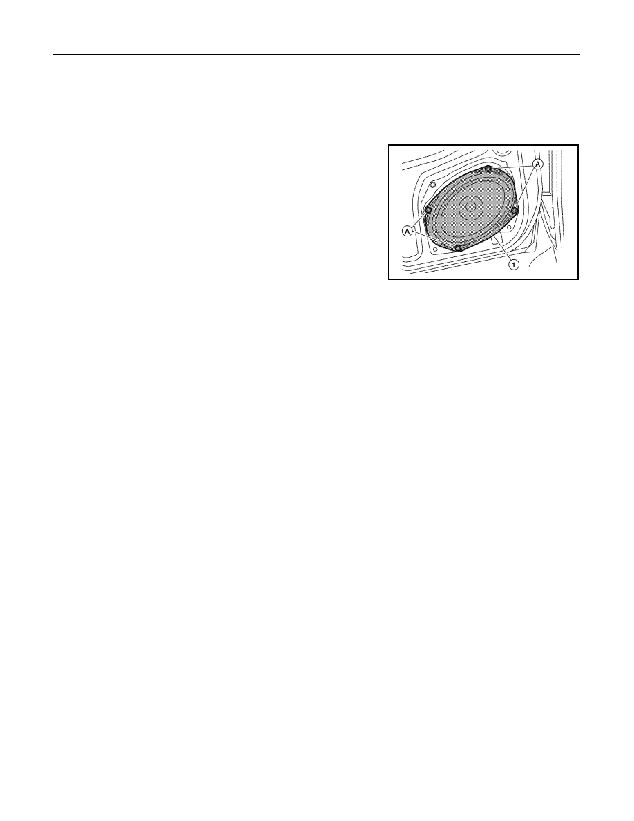
FRONT DOOR SPEAKER
FRONT DOOR SPEAKER
Removal and Installation
INFOID:0000000007347946
REMOVAL
1. Remove the front door finisher. Refer to
INT-15, "Removal and Installation"
2. Remove the front door speaker screws (A).
3. Pull out the front door speaker (1), and disconnect the front door
speaker connector and remove the front door speaker (1).
INSTALLATION
Installation is in the reverse order of removal.
ALNIA0347ZZ
August 2012
2012 Pathfinder
AV
REAR DOOR SPEAKER
AV-425
< REMOVAL AND INSTALLATION >
[BOSE AUDIO WITH NAVIGATION]
C
D
E
F
G
H
I
J
K
L
M
B
A
O
P
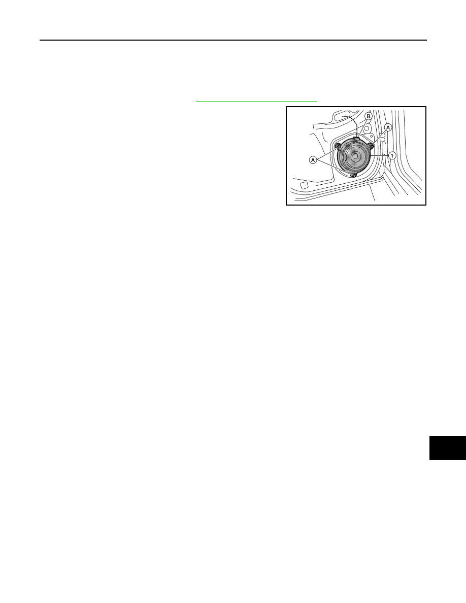
REAR DOOR SPEAKER
Removal and Installation of Rear Door Speaker
INFOID:0000000007347947
REMOVAL
1. Remove the rear door finisher. Refer to
INT-15, "Removal and Installation"
.
2. Remove the rear door speaker screws (A).
3. Disconnect the rear door speaker connector (B) and remove
rear door speaker (1).
INSTALLATION
Installation is in the reverse order of removal.
ALNIA0348ZZ
August 2012
2012 Pathfinder
Нет комментариевНе стесняйтесь поделиться с нами вашим ценным мнением.
Текст