Nissan Pathfinder (2012 year). Instruction — part 426
HAC-130
< BASIC INSPECTION >
[MANUAL AIR CONDITIONER]
INSPECTION AND ADJUSTMENT
If NG, go to trouble diagnosis procedure for
HAC-160, "Magnet Clutch Diagnosis Procedure"
If OK, continue with next check.
August 2012
2012 Pathfinder
FUNCTION INFORMATION
HAC-131
< SYSTEM DESCRIPTION >
[MANUAL AIR CONDITIONER]
C
D
E
F
G
H
J
K
L
M
A
B
HAC
N
O
P
SYSTEM DESCRIPTION
FUNCTION INFORMATION
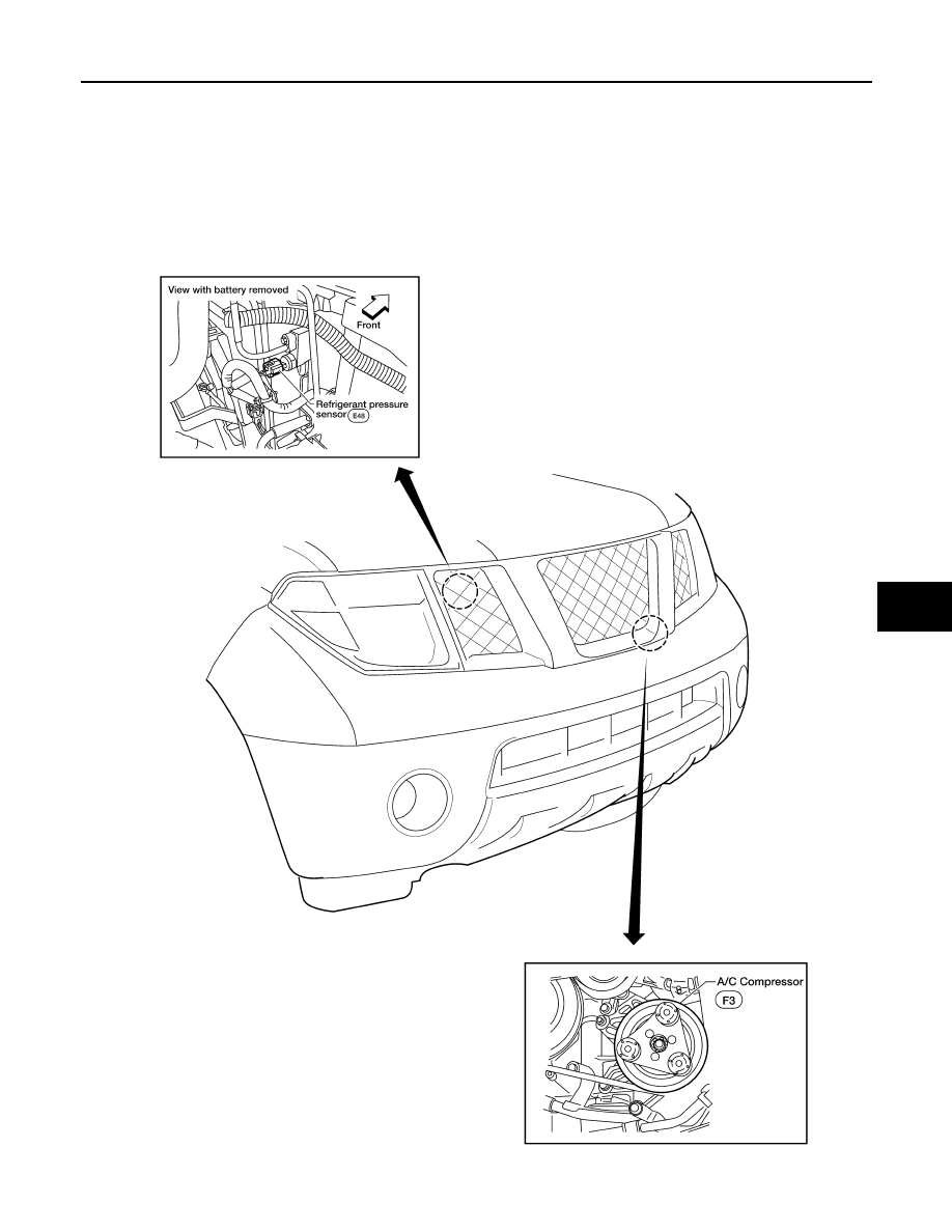
Component Part Location
INFOID:0000000007356415
ENGINE COMPARTMENT
WJIA1489E
August 2012
2012 Pathfinder
HAC-132
< SYSTEM DESCRIPTION >
[MANUAL AIR CONDITIONER]
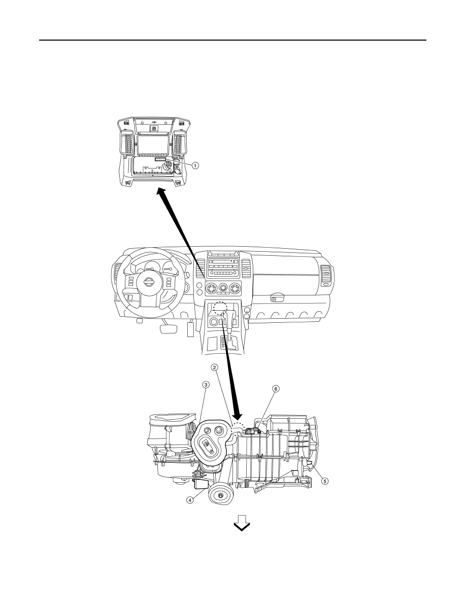
FUNCTION INFORMATION
PASSENGER COMPARTMENT
1.
Front air control M52
2.
Intake sensor M146
3.
Intake door motor M58
4.
Front blower motor resistor M121
5.
Mode door motor M144
6.
Air mix door motor (front) M149
AWIIA1194GB
August 2012
2012 Pathfinder

FUNCTION INFORMATION
HAC-133
< SYSTEM DESCRIPTION >
[MANUAL AIR CONDITIONER]
C
D
E
F
G
H
J
K
L
M
A
B
HAC
N
O
P
Symptom Table
INFOID:0000000007356416
Symptom
Reference Page
A/C system does not come on.
Go to Trouble Diagnosis Procedure for A/C System.
Air outlet does not change.
Go to Trouble Diagnosis Procedure for Mode Door Motor.
Mode door motor is malfunctioning.
Discharge air temperature does not change.
Go to Trouble Diagnosis Procedure for Air Mix Door Motor.
Air mix door motor is malfunctioning.
Intake door does not change.
Go to Trouble Diagnosis Procedure for Intake Door Motor.
Intake door motor is malfunctioning.
Front blower motor operation is malfunctioning. Go to Trouble Diagnosis Procedure for Front Blower Motor.
Magnet clutch does not engage.
Go to Trouble Diagnosis Procedure for Magnet Clutch.
Insufficient cooling
Go to Trouble Diagnosis Procedure for Insufficient Cooling.
Insufficient heating
Go to Trouble Diagnosis Procedure for Insufficient Heating.
Noise
Go to Trouble Diagnosis Procedure for Noise.
August 2012
2012 Pathfinder
HAC-134
< SYSTEM DESCRIPTION >
[MANUAL AIR CONDITIONER]
REFRIGERATION SYSTEM
REFRIGERATION SYSTEM
Refrigerant Cycle
INFOID:0000000007356417
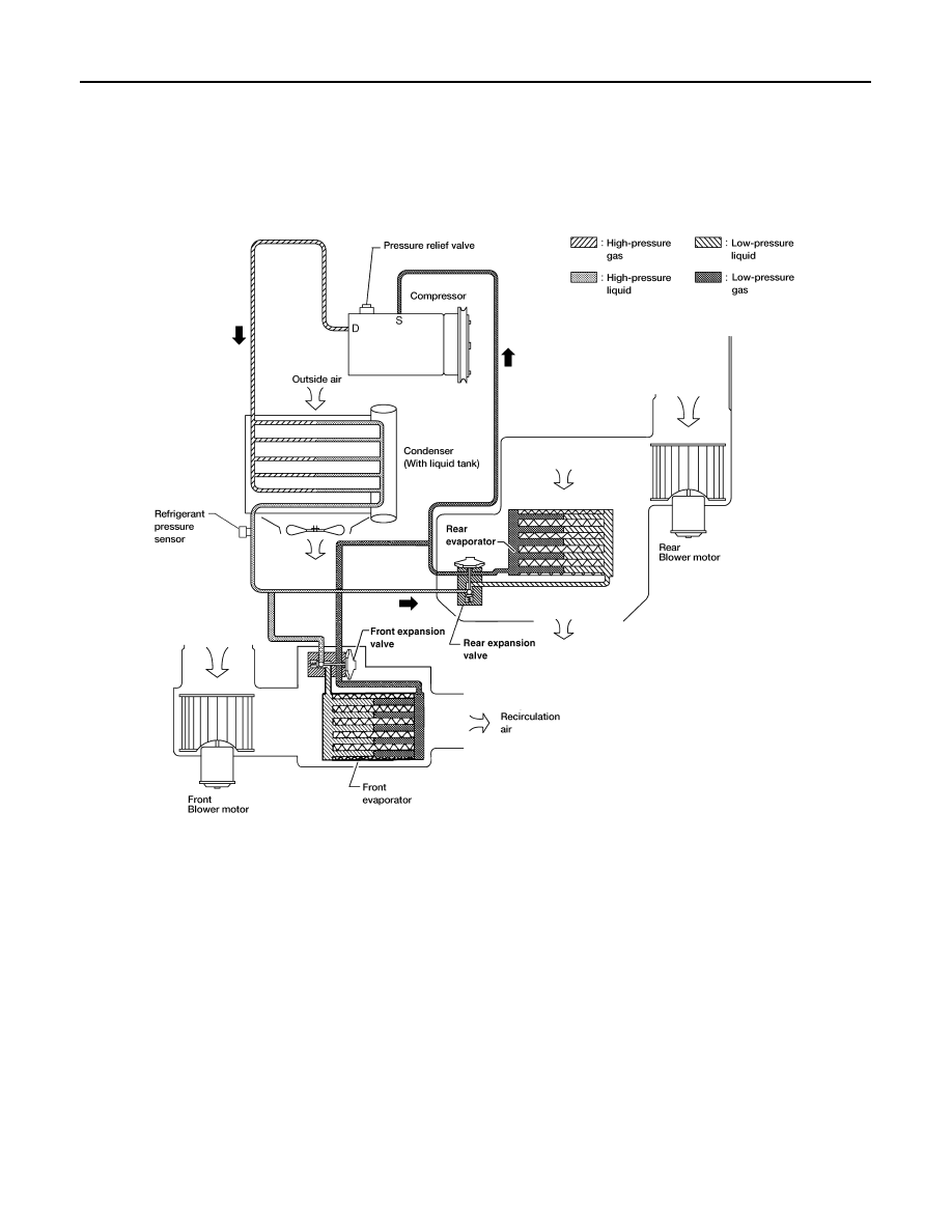
REFRIGERANT FLOW
The refrigerant flows in the standard pattern, that is, through the compressor, the condenser with liquid tank,
through the front and rear evaporators, and back to the compressor. The refrigerant evaporation through the
evaporator coils are controlled by front and rear externally equalized expansion valves, located inside the front
and rear evaporator cases.
FREEZE PROTECTION
The compressor cycles on and off to maintain the evaporator temperature within a specified range. When the
evaporator coil temperature falls below a specified point, the intake sensor interrupts the compressor opera-
tion. When the evaporator coil temperature rises above the specification, the intake sensor allows compressor
operation.
Refrigerant System Protection
INFOID:0000000007356418
REFRIGERANT PRESSURE SENSOR
WJIA1342E
August 2012
2012 Pathfinder
REFRIGERATION SYSTEM
HAC-135
< SYSTEM DESCRIPTION >
[MANUAL AIR CONDITIONER]
C
D
E
F
G
H
J
K
L
M
A
B
HAC
N
O
P
The refrigerant system is protected against excessively high- or low-pressures by the refrigerant pressure sen-
sor, located on the condenser. If the system pressure rises above or falls below the specifications, the refriger-
ant pressure sensor detects the pressure inside the refrigerant line and sends a voltage signal to the ECM.
The ECM de-energizes the A/C relay to disengage the magnetic compressor clutch when pressure on the high
pressure side detected by refrigerant pressure sensor is over about 2,746 kPa (28 kg/cm
2
, 398 psi), or below
about 120 kPa (1.22 kg/cm
2
, 17.4 psi).
PRESSURE RELIEF VALVE
The refrigerant system is also protected by a pressure relief valve, located in the rear head of the compressor.
When the pressure of refrigerant in the system increases to an abnormal level [more than 2,990 kPa (30.5 kg/
cm
2
, 433.6 psi)], the release port on the pressure relief valve automatically opens and releases refrigerant into
the atmosphere.
August 2012
2012 Pathfinder
HAC-136
< SYSTEM DESCRIPTION >
[MANUAL AIR CONDITIONER]
MANUAL AIR CONDITIONER SYSTEM
MANUAL AIR CONDITIONER SYSTEM
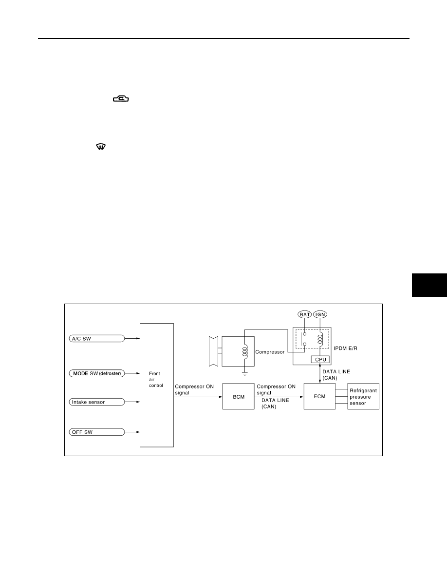
Control System Diagram
INFOID:0000000007356419
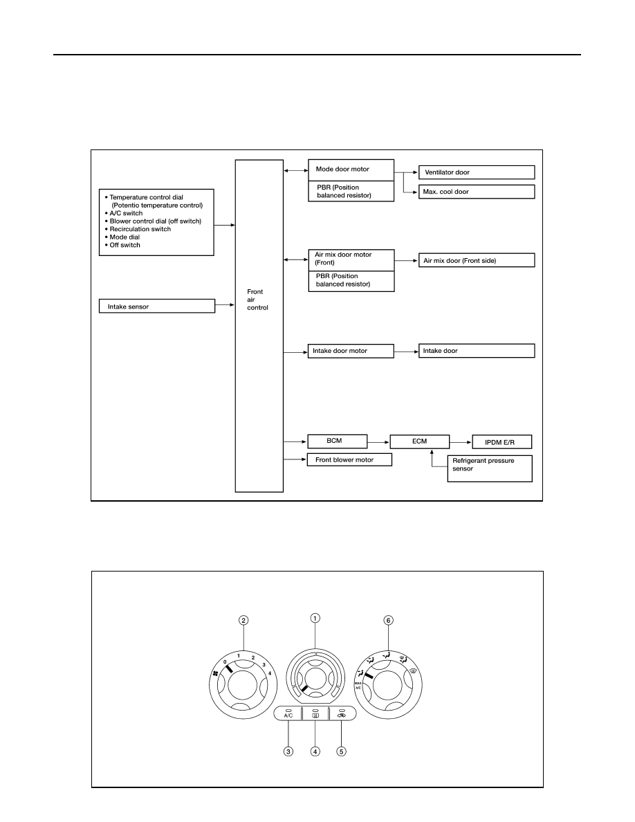
CONTROL SYSTEM
The control system consists of input sensors, switches, the front air control (microcomputer) and outputs.
The relationship of these components is shown in the figure below:
Control System Description
INFOID:0000000007356420
CONTROL OPERATION
Front air control
AWIIA0592GB
WJIA1510E
August 2012
2012 Pathfinder
MANUAL AIR CONDITIONER SYSTEM
HAC-137
< SYSTEM DESCRIPTION >
[MANUAL AIR CONDITIONER]
C
D
E
F
G
H
J
K
L
M
A
B
HAC
N
O
P
TEMPERATURE CONTROL DIAL (TEMPERATURE CONTROL)
Increases or decreases the set temperature.
RECIRCULATION (
) SWITCH
• When REC switch is ON, REC switch indicator turns ON, and air inlet is set to REC.
• When REC switch is turned OFF, or when compressor is turned from ON to OFF, REC switch is automati-
cally turned OFF. REC mode can be re-entered by pressing REC switch again.
• REC switch is not operated when DEF switch is turned ON, or at the D/F or FOOT position.
DEFROSTER (
) SWITCH
Positions the air outlet doors to the defrost position. Also positions the intake doors to the outside air position.
REAR WINDOW DEFOGGER SWITCH
When switch is ON, rear window is defogged.
OFF SWITCH (BLOWER SPEED SET TO 0)
The compressor and blower are OFF.
A/C SWITCH
The compressor is ON or OFF.
(Pressing the A/C switch will turn off the A/C switch and compressor.)
MODE DIAL
Controls the air discharge outlets.
FRONT BLOWER CONTROL DIAL
Instructionly controls the four blower speeds.
MAGNET CLUTCH CONTROL
When the A/C switch is pressed, or the mode dial is turned to the DEF or D/F position, the front air control out-
puts a compressor ON signal to BCM.
The BCM then sends a compressor ON signal to ECM, via CAN communication line.
ECM judges whether compressor can be turned ON, based on each sensor status (refrigerant pressure sen-
sor signal, throttle angle sensor, etc.). If it judges compressor can be turned ON, it sends compressor ON sig-
nal to IPDM E/R, via CAN communication line.
Upon receipt of compressor ON signal from ECM, IPDM E/R turns air conditioner relay ON to operate com-
pressor.
1.
Temperature control dial
2.
Blower control dial
3.
A/C switch
4.
Rear window defogger switch
5.
Recirculation switch
6.
Mode dial
WJIA1293E
August 2012
2012 Pathfinder
Нет комментариевНе стесняйтесь поделиться с нами вашим ценным мнением.
Текст