Nissan Pathfinder (2012 year). Instruction — part 478
MWI
BCM (BODY CONTROL MODULE)
MWI-49
< ECU DIAGNOSIS INFORMATION >
C
D
E
F
G
H
I
J
K
L
M
B
A
O
P
1: With remote keyless entry system
2: With Intelligent Key system
Fail Safe
INFOID:0000000007830115
Fail-safe index
BCM performs fail-safe control when any DTC listed below is detected.
DTC Inspection Priority Chart
INFOID:0000000007830116
If some DTCs are displayed at the same time, perform inspections one by one based on the following priority
chart.
60
LG
Turn signal (left)
Output
ON
Turn left ON
61
G
Turn signal (right)
Output
ON
Turn right ON
63
BR
Interior room/map
lamp
Output
OFF
Any door
switch
ON (open)
0V
OFF (closed)
Battery voltage
65
V
All door lock actuators
(lock)
Output
OFF
OFF (neutral)
0V
ON (lock)
Battery voltage
66
L
Front door lock actua-
tor RH, rear door lock
actuators LH/RH and
glass hatch lock actu-
ator (unlock)
Output
OFF
OFF (neutral)
0V
ON (unlock)
Battery voltage
67
B
Ground
Input
ON
—
0V
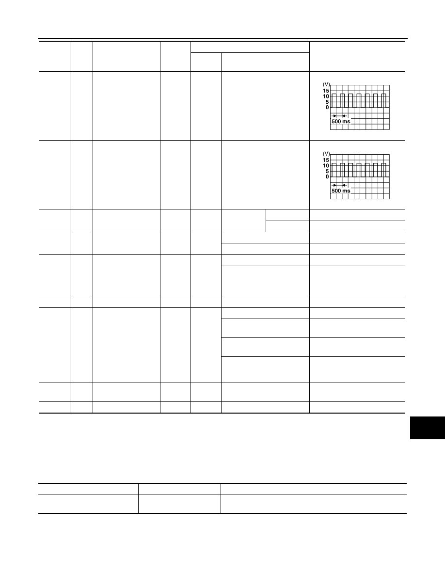
68
W/R
Power window power
supply (RAP)
Output
—
Ignition switch ON
Battery voltage
Within 45 seconds after igni-
tion switch OFF
Battery voltage
More than 45 seconds after ig-
nition switch OFF
0V
When front door LH or RH is
open or power window timer
operates
0V
69
L
Power window power
supply
Output
—
—
Battery voltage
70
W
Battery power supply
Input
OFF
—
Battery voltage
Terminal
Wire
color
Signal name
Signal
input/
output
Measuring condition
Reference value or waveform
(Approx.)
Ignition
switch
Operation or condition
SKIA3009J
SKIA3009J
Display contents of CONSULT
Fail-safe
Cancellation
U1000: CAN COMM CIRCUIT
Inhibit engine cranking
When the BCM re-establishes communication with the other mod-
ules.
August 2012
2012 Pathfinder

MWI-50
< ECU DIAGNOSIS INFORMATION >
BCM (BODY CONTROL MODULE)
DTC Index
INFOID:0000000007830117
NOTE:
Details of time display
• CRNT: Displays when there is a malfunction now or after returning to the normal condition until turning igni-
tion switch OFF
→
ON again.
• 1 - 39: Displayed if any previous malfunction is present when current condition is normal. It increases like 1
→
2
→
3...38
→
39 after returning to the normal condition whenever ignition switch OFF
→
ON. The counter
remains at 39 even if the number of cycles exceeds it. It is counted from 1 again when turning ignition switch
OFF
→
ON after returning to the normal condition if the malfunction is detected again.
Priority
DTC
1
• U1000: CAN COMM CIRCUIT
2
• B2190: NATS ANTENNA AMP
• B2191: DIFFERENCE OF KEY
• B2192: ID DISCORD BCM-ECM
• B2193: CHAIN OF BCM-ECM
• B2013: STRG COMM 1
• B2552: INTELLIGENT KEY
• B2590: NATS MALFUNCTION
3
• C1729: VHCL SPEED SIG ERR
• C1735: IGNITION SIGNAL
4
• C1704: LOW PRESSURE FL
• C1705: LOW PRESSURE FR
• C1706: LOW PRESSURE RR
• C1707: LOW PRESSURE RL
• C1708: [NO DATA] FL
• C1709: [NO DATA] FR
• C1710: [NO DATA] RR
• C1711: [NO DATA] RL
• C1712: [CHECKSUM ERR] FL
• C1713: [CHECKSUM ERR] FR
• C1714: [CHECKSUM ERR] RR
• C1715: [CHECKSUM ERR] RL
• C1716: [PRESSDATA ERR] FL
• C1717: [PRESSDATA ERR] FR
• C1718: [PRESSDATA ERR] RR
• C1719: [PRESSDATA ERR] RL
• C1720: [CODE ERR] FL
• C1721: [CODE ERR] FR
• C1722: [CODE ERR] RR
• C1723: [CODE ERR] RL
• C1724: [BATT VOLT LOW] FL
• C1725: [BATT VOLT LOW] FR
• C1726: [BATT VOLT LOW] RR
• C1727: [BATT VOLT LOW] RL
CONSULT display
Fail-safe
Intelligent Key
warning lamp ON
Low tire pressure
warning lamp ON
Reference page
No DTC is detected.
Further testing may be required.
—
—
—
—
U1000: CAN COMM CIRCUIT
X
—
—
B2013: STRG COMM 1
—
—
—
B2190: NATS ANTENNA AMP
—
—
—
(with I-Key)
(without I-
Key)
B2191: DIFFERENCE OF KEY
—
—
—
(with I-Key)
(without I-
Key)
August 2012
2012 Pathfinder

MWI
BCM (BODY CONTROL MODULE)
MWI-51
< ECU DIAGNOSIS INFORMATION >
C
D
E
F
G
H
I
J
K
L
M
B
A
O
P
B2192: ID DISCORD BCM-ECM
—
—
—
(with I-Key)
(without I-
Key)
B2193: CHAIN OF BCM-ECM
—
—
—
(with I-Key)
(without I-
Key)
B2552: INTELLIGENT KEY
—
—
—
B2590: NATS MALFUNCTION
—
—
—
C1708: [NO DATA] FL
—
—
X
C1709: [NO DATA] FR
—
—
X
C1710: [NO DATA] RR
—
—
X
C1711: [NO DATA] RL
—
—
X
C1712: [CHECKSUM ERR] FL
—
—
X
C1713: [CHECKSUM ERR] FR
—
—
X
C1714: [CHECKSUM ERR] RR
—
—
X
C1715: [CHECKSUM ERR] RL
—
—
X
C1716: [PRESSDATA ERR] FL
—
—
X
C1717: [PRESSDATA ERR] FR
—
—
X
C1718: [PRESSDATA ERR] RR
—
—
X
C1719: [PRESSDATA ERR] RL
—
—
X
C1720: [CODE ERR] FL
—
—
X
C1721: [CODE ERR] FR
—
—
X
C1722: [CODE ERR] RR
—
—
X
C1723: [CODE ERR] RL
—
—
X
C1724: [BATT VOLT LOW] FL
—
—
X
C1725: [BATT VOLT LOW] FR
—
—
X
C1726: [BATT VOLT LOW] RR
—
—
X
C1727: [BATT VOLT LOW] RL
—
—
X
C1729: VHCL SPEED SIG ERR
—
—
X
C1735: IGNITION SWITCH
—
—
X
CONSULT display
Fail-safe
Intelligent Key
warning lamp ON
Low tire pressure
warning lamp ON
Reference page
August 2012
2012 Pathfinder

MWI-52
< ECU DIAGNOSIS INFORMATION >
IPDM E/R (INTELLIGENT POWER DISTRIBUTION MODULE ENGINE ROOM)
IPDM E/R (INTELLIGENT POWER DISTRIBUTION MODULE ENGINE
ROOM)
Reference Value
INFOID:0000000007830119
VALUES ON THE DIAGNOSIS TOOL
Monitor Item
Condition
Value/Status
MOTOR FAN REQ
Engine idle speed
Changes depending on engine
coolant temperature, air conditioner
operation status, vehicle speed,
etc.
1, 2, 3, 4
AC COMP REQ
A/C switch OFF
Off
A/C switch ON
On
TAIL&CLR REQ
Lighting switch OFF
Off
Lighting switch 1ST, 2ND, HI or AUTO (Light is illuminated)
On
HL LO REQ
Lighting switch OFF
Off
Lighting switch 2ND HI or AUTO (Light is illuminated)
On
HL HI REQ
Lighting switch OFF
Off
Lighting switch HI
On
FR FOG REQ
Lighting switch 2ND or AUTO (Light
is illuminated)
Front fog lamp switch OFF
Off
• Front fog lamp switch ON
• Daytime light activated (Canada
only)
On
FR WIP REQ
Ignition switch ON
Front wiper switch OFF
Stop
Front wiper switch INT
1LOW
Front wiper switch LO
Low
Front wiper switch HI
Hi
WIP AUTO STOP
Ignition switch ON
Front wiper stop position
STOP P
Any position other than front wiper
stop position
ACT P
WIP PROT
Ignition switch ON
Front wiper operates normally
Off
Front wiper stops at fail-safe opera-
tion
BLOCK
ST RLY REQ
Ignition switch OFF or ACC
Off
Ignition switch START
On
IGN RLY
Ignition switch OFF or ACC
Off
Ignition switch ON
On
RR DEF REQ
Rear defogger switch OFF
Off
Rear defogger switch ON
On
OIL P SW
Ignition switch OFF, ACC or engine running
Open
Ignition switch ON
Close
DTRL REQ
Daytime light system requested OFF with CONSULT.
Off
Daytime light system requested ON with CONSULT.
On
THFT HRN REQ
Not operated
Off
• Panic alarm is activated
• Horn is activated with VEHICLE SECURITY (THEFT WARNING) SYS-
TEM
On
August 2012
2012 Pathfinder
MWI
IPDM E/R (INTELLIGENT POWER DISTRIBUTION MODULE ENGINE ROOM)
MWI-53
< ECU DIAGNOSIS INFORMATION >
C
D
E
F
G
H
I
J
K
L
M
B
A
O
P
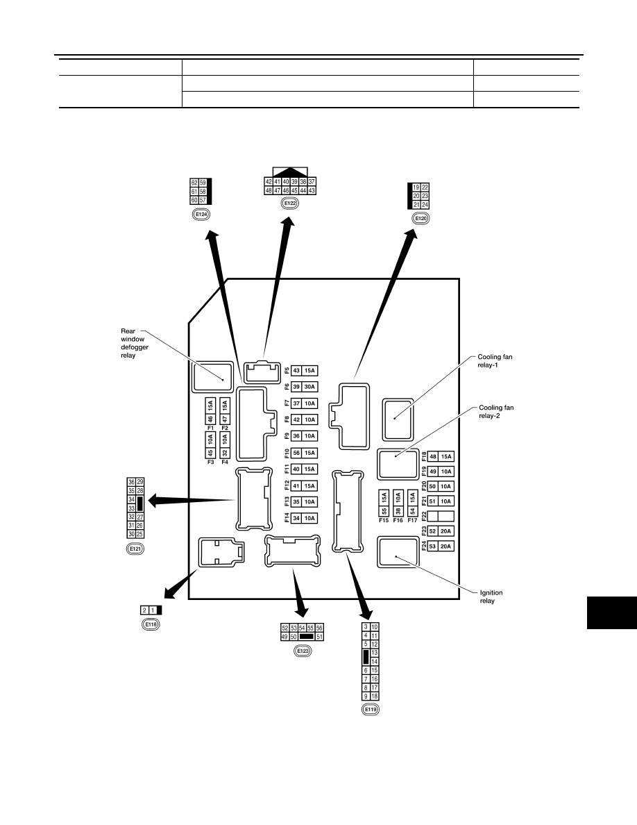
Terminal Layout
INFOID:0000000007830120
NOTE:
Numbers preceded by an "F" represent the fuse numbers imprinted on the IPDM E/R. The other numbers rep-
resent the fuse numbers as they appear in the wiring diagrams.
HORN CHIRP
Not operated
Off
Door locking with keyfob or Intelligent Key (if equipped) (horn chirp mode) On
Monitor Item
Condition
Value/Status
AAMIA0386GB
August 2012
2012 Pathfinder

MWI-54
< ECU DIAGNOSIS INFORMATION >
IPDM E/R (INTELLIGENT POWER DISTRIBUTION MODULE ENGINE ROOM)
Physical Values
INFOID:0000000007830121
PHYSICAL VALUES
Terminal
Wire
color
Signal name
Signal
input/
output
Measuring condition
Reference value
(Approx.)
Igni-
tion
switch
Operation or condition
1
W
Battery power supply
Input
OFF
—
Battery voltage
2
R
Battery power supply
Input
OFF
—
Battery voltage
3
G
ECM relay
Output
—
Ignition switch ON or START
Battery voltage
Ignition switch OFF or ACC
0V
4
P
ECM relay
Output
—
Ignition switch ON or START
Battery voltage
Ignition switch OFF or ACC
0V
6
V
Throttle control motor
relay
Output
—
Ignition switch ON or START
Battery voltage
Ignition switch OFF or ACC
0V
7
BR
ECM relay control
Input
—
Ignition switch ON or START
0V
Ignition switch OFF or ACC
Battery voltage
8
W/R
Fuse 54
Output
—
Ignition switch ON or START
Battery voltage
Ignition switch OFF or ACC
0V
10
R/B
Fuse 45
Output
ON
Daytime light system active
0V
Daytime light system inactive
Battery voltage
11
Y
A/C compressor
Output
ON or
START
A/C switch ON or defrost A/C
switch
Battery voltage
A/C switch OFF or defrost A/C
switch
0V
12
W/G
Ignition switch sup-
plied power
Input
—
OFF or ACC
0V
ON or START
Battery voltage
13
R
Fuel pump relay
Output
—
Ignition switch ON or START
Battery voltage
Ignition switch OFF or ACC
0V
14
W/G
Fuse 49
Output
—
Ignition switch ON or START
Battery voltage
Ignition switch OFF or ACC
0V
15
W/R
Fuse 50 (ABS)
Output
—
Ignition switch ON or START
Battery voltage
Ignition switch OFF or ACC
0V
16
W/G
Fuse 51
Output
—
Ignition switch ON or START
Battery voltage
Ignition switch OFF or ACC
0V
17
W/G
Fuse 55
Output
—
Ignition switch ON or START
Battery voltage
Ignition switch OFF or ACC
0V
19
W
Starter motor
Output
START
—
Battery voltage
20
BR
Cooling fan motor
(low)
Output
ON or
START
—
Battery voltage
21
GR
Ignition switch sup-
plied power
Input
—
OFF or ACC
0V
START
Battery voltage
22
G
Battery power supply
Output
OFF
—
Battery voltage
23
LG
Door mirror defogger
output signal
Output
—
When rear defogger switch is
ON
Battery voltage
When raker defogger switch is
OFF
0V
August 2012
2012 Pathfinder
MWI
IPDM E/R (INTELLIGENT POWER DISTRIBUTION MODULE ENGINE ROOM)
MWI-55
< ECU DIAGNOSIS INFORMATION >
C
D
E
F
G
H
I
J
K
L
M
B
A
O
P
24
P
Cooling fan motor
(high)
Output
—
Conditions correct for cooling
fan operation
Battery voltage
Conditions not correct for
cooling fan operation
0V
27
W
Fuse 38
Output
—
Ignition switch ON or START
Battery voltage
Ignition switch OFF or ACC
0V
28
R
LH front parking and
front side marker lamp
Output
OFF
Lighting
switch 1st po-
sition
OFF
0V
ON
Battery voltage
29
G
Trailer tow relay
Output
ON
Lighting
switch 1st po-
sition
OFF
0V
ON
Battery voltage
30
R/B
Fuse 53
Output
—
Ignition switch ON or START
Battery voltage
Ignition switch OFF or ACC
0V
32
GR
Wiper low speed sig-
nal
Output
ON or
START
Wiper switch
OFF
Battery voltage
LO or INT
0V
35
L
Wiper high speed sig-
nal
Output
ON or
START
Wiper switch
OFF, LO, INT
Battery voltage
HI
0V
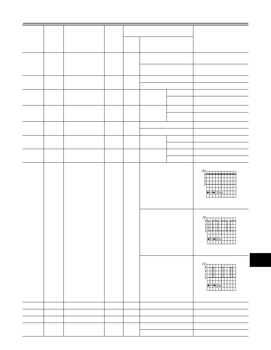
37
Y
Power generation
command signal
Output
—
Ignition switch ON
6.3 V
40% is set on "Active test,"
"ALTERNATOR DUTY" of
"ENGINE"
3.8 V
40% is set on "Active test,"
"ALTERNATOR DUTY" of
"ENGINE"
1.4 V
38
B
Ground
Input
—
—
0V
39
L
CAN-H
—
ON
—
—
40
P
CAN-L
—
ON
—
—
42
GR
Oil pressure switch
Input
—
Engine running
Battery voltage
Engine stopped
0V
Terminal
Wire
color
Signal name
Signal
input/
output
Measuring condition
Reference value
(Approx.)
Igni-
tion
switch
Operation or condition
JPMIA0001GB
JPMIA0002GB
JPMIA0003GB
August 2012
2012 Pathfinder

MWI-56
< ECU DIAGNOSIS INFORMATION >
IPDM E/R (INTELLIGENT POWER DISTRIBUTION MODULE ENGINE ROOM)
43
G
Wiper auto stop signal
Input
ON or
START
Wiper switch
OFF, LO, INT
Battery voltage
44
R
Daytime light relay
control
Input
ON
Daytime light system active
0V
Daytime light system inactive
Battery voltage
45
LG
Horn relay control
Input
ON
When door locks are operated
using keyfob or Intelligent Key
(if equipped) (OFF
→
ON)*
Battery voltage
→
0V
46
V
Fuel pump relay con-
trol
Input
—
Ignition switch ON or START
0V
Ignition switch OFF or ACC
Battery voltage
47
O
Throttle control motor
relay control
Input
—
Ignition switch ON or START
0V
Ignition switch OFF or ACC
Battery voltage
48
R
Starter relay (range
switch)
Input
ON or
START
Selector lever in "P" or "N"
0V
Selector lever any other posi-
tion
Battery voltage
49
GR
Front RH parking and
front side marker lamp
Output
OFF
Lighting
switch 1st po-
sition
OFF
0V
ON
Battery voltage
50
W
Front fog lamp (LH)
Output
ON or
START
Lighting
switch must
be in the 2nd
position
(LOW beam
is ON) and
the front fog
lamp switch
OFF
0V
ON
Battery voltage
51
V
Front fog lamp (RH)
Output
ON or
START
Lighting
switch must
be in the 2nd
position
(LOW beam
is ON) and
the front fog
lamp switch
OFF
0V
ON
Battery voltage
52
P
LH low beam head-
lamp
Output
—
Lighting switch in 2nd position
Battery voltage
54
R
RH low beam head-
lamp
Output
—
Lighting switch in 2nd position
Battery voltage
55
G
LH high beam head-
lamp
Output
—
Lighting switch in 2nd position
and placed in HIGH or PASS
position
Battery voltage
56
L
RH high beam head-
lamp
Output
—
Lighting switch in 2nd position
and placed in HIGH or PASS
position
Battery voltage
57
GR
Parking, license, and
tail lamp
Output
ON
Lighting
switch 1st po-
sition
OFF
0V
ON
Battery voltage
59
B
Ground
Input
—
—
0V
60
GR
Rear window defog-
ger relay
Output
ON or
START
Rear defogger switch ON
Battery voltage
Rear defogger switch OFF
0V
61
R/B
Fuse 32
Output
OFF
—
Battery voltage
Terminal
Wire
color
Signal name
Signal
input/
output
Measuring condition
Reference value
(Approx.)
Igni-
tion
switch
Operation or condition
August 2012
2012 Pathfinder
Нет комментариевНе стесняйтесь поделиться с нами вашим ценным мнением.
Текст