Nissan Pathfinder (2012 year). Instruction — part 32
AV-74
< DTC/CIRCUIT DIAGNOSIS >
[MID AUDIO]
RGB AREA (YS) SIGNAL CIRCUIT
RGB AREA (YS) SIGNAL CIRCUIT
Description
INFOID:0000000007347642
Transmits the display area of RGB image displayed by AV control unit with RGB area (YS) signal to display
unit.
Diagnosis Procedure
INFOID:0000000007347643
Regarding Wiring Diagram information, refer to
1.
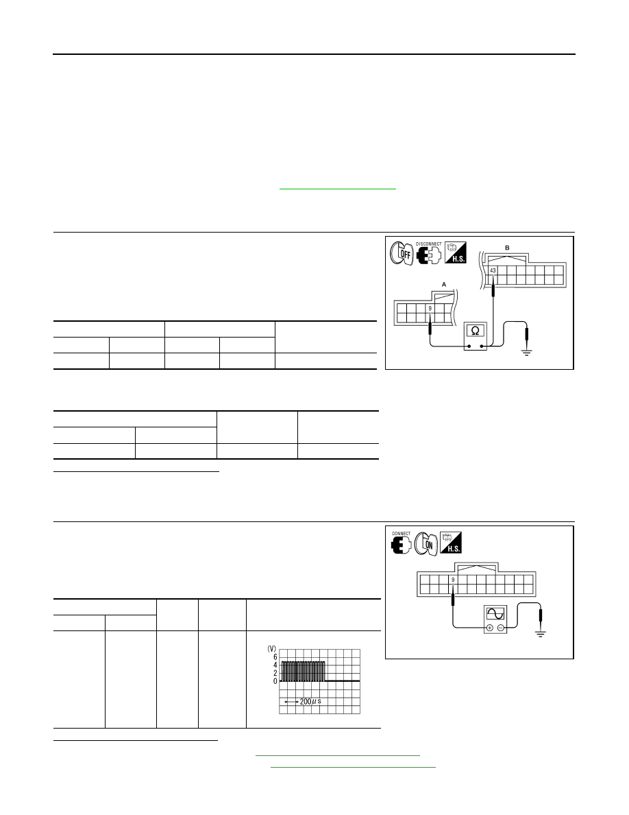
CHECK CONTINUITY RGB AREA (YS) SIGNAL CIRCUIT
1. Turn ignition switch OFF.
2. Disconnect display unit connector M93 and AV control unit con-
nector M133.
3. Check continuity between display unit harness connector M93
(A) terminal 9 and AV control unit harness connector M133 (B)
terminal 43.
4. Check continuity between display unit harness connector M93
(A) terminal 9 and ground.
Are continuity results as specified?
YES
>> GO TO 2
NO
>> Repair harness or connector.
2.
CHECK RGB SYNCHRONIZING SIGNAL
1. Connect display unit connector M93 and AV control unit connec-
tor M133.
2. Turn ignition switch ON.
3. Check signal between display unit harness connector M93 ter-
minal 9 and ground.
Are voltage readings as specified?
YES
>> Replace display unit. Refer to
AV-116, "Removal and Installation"
.
NO
>> Replace AV control unit. Refer to
AV-114, "Removal and Installation"
A
B
Continuity
Connector
Terminal
Connector
Terminal
M93
9
M133
43
Yes
A
—
Continuity
Connector
Terminal
M93
9
Ground
No
ALNIA0390GB
(+)
(-)
Condition
Reference signal
Connector
Terminal
M93
9
Ground
Receive
audio sig-
nal
ALNIA0391GB
PKIB4948J
August 2012
2012 Pathfinder
AV
HORIZONTAL SYNCHRONIZING (HP) SIGNAL CIRCUIT
AV-75
< DTC/CIRCUIT DIAGNOSIS >
[MID AUDIO]
C
D
E
F
G
H
I
J
K
L
M
B
A
O
P
HORIZONTAL SYNCHRONIZING (HP) SIGNAL CIRCUIT
Description
INFOID:0000000007347644
In composite image (AUX image, camera image), transmit the vertical synchronizing (VP) signal and horizon-
tal synchronizing (HP) signal from display unit to AV control unit so as to synchronize the RGB images dis-
played with AV control unit such as the image quality adjusting menu, etc.
Diagnosis Procedure
INFOID:0000000007347645
Regarding Wiring Diagram information, refer to
1.
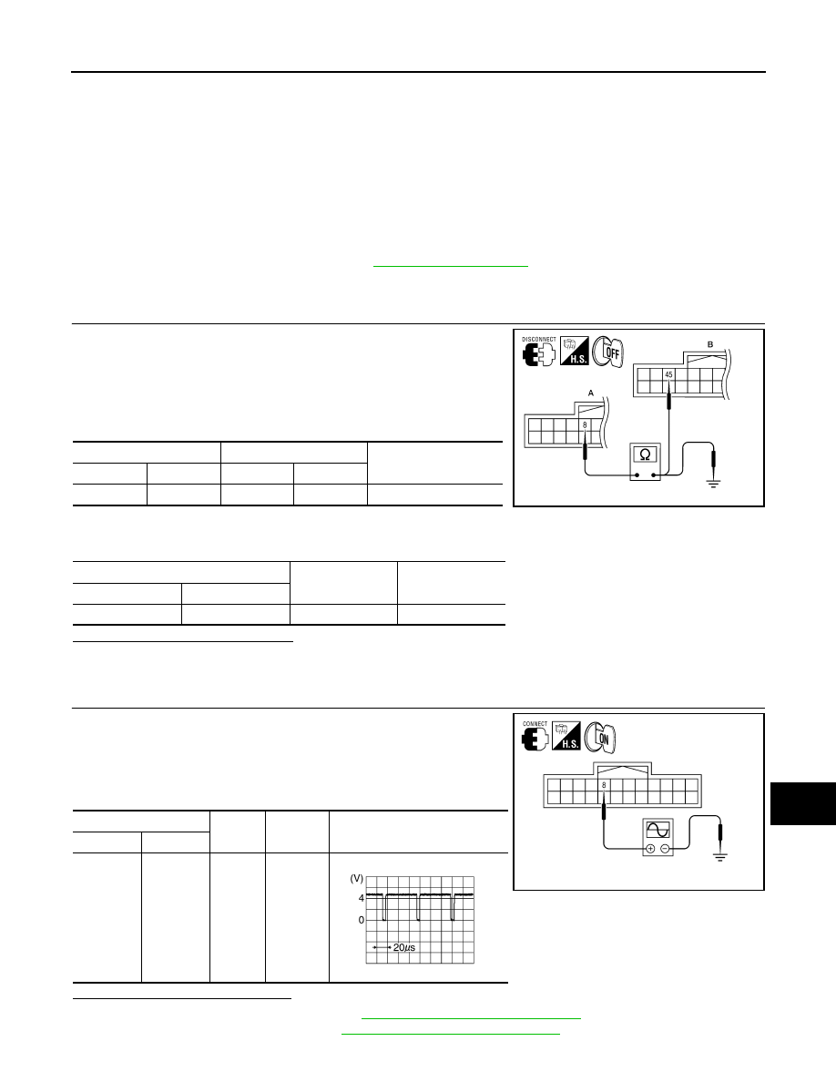
CHECK CONTINUITY HORIZONTAL SYNCHRONIZING (HP) SIGNAL CIRCUIT
1. Turn ignition switch OFF.
2. Disconnect display unit connector M93 and AV control unit con-
nector M133.
3. Check continuity between display unit harness connector M93
(A) terminal 8 and AV control unit harness connector M133 (B)
terminal 45.
4. Check continuity between display unit harness connector M93
(A) terminal 8 and ground.
Are continuity results as specified?
YES
>> GO TO 2
NO
>> Repair harness or connector.
2.
CHECK HORIZONTAL SYNCHRONIZING (HP) SIGNAL
1. Connect display unit connector M93 and AV control unit connec-
tor M133.
2. Turn ignition switch ON.
3. Check signal between display unit harness connector M93 ter-
minal 8 and ground.
Are voltage readings as specified?
YES
>> Replace AV control unit. Refer to
AV-114, "Removal and Installation"
NO
>> Replace display unit. Refer to
AV-116, "Removal and Installation"
.
A
B
Continuity
Connector
Terminal
Connector
Terminal
M93
8
M133
45
Yes
A
—
Continuity
Connector
Terminal
M93
8
Ground
No
ALNIA0394GB
(+)
(-)
Condition
Reference signal
Connector
Terminal
M93
8
Ground
Receive
audio sig-
nal
ALNIA0396GB
SKIB3601E
August 2012
2012 Pathfinder
AV-76
< DTC/CIRCUIT DIAGNOSIS >
[MID AUDIO]
VERTICAL SYNCHRONIZING (VP) SIGNAL CIRCUIT
VERTICAL SYNCHRONIZING (VP) SIGNAL CIRCUIT
Description
INFOID:0000000007347646
In composite image (AUX image, camera image), transmit the vertical synchronizing (VP) signal and horizon-
tal synchronizing (HP) signal from display unit to AV control unit so as to synchronize the RGB images dis-
played with AV control unit such as the image quality adjusting menu, etc.
Diagnosis Procedure
INFOID:0000000007347647
Regarding Wiring Diagram information, refer to
1.
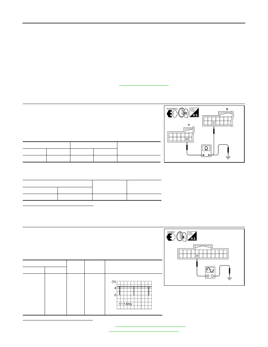
CHECK CONTINUITY VERTICAL SYNCHRONIZING (VP) SIGNAL CIRCUIT
1. Turn ignition switch OFF.
2. Disconnect display unit connector M93 and AV control unit con-
nector M133.
3. Check continuity between display unit harness connector M93
(A) terminal 20 and AV control unit harness connector M133 (B)
terminal 57.
4. Check continuity between display unit harness connector M93
(A) terminal 20 and ground.
Are continuity results as specified?
YES
>> GO TO 2
NO
>> Repair harness or connector.
2.
CHECK VERTICAL SYNCHRONIZING (VP) SIGNAL
1. Connect display unit connector M93 and AV control unit connec-
tor M133.
2. Turn ignition switch ON.
3. Check signal between display unit harness connector M93 ter-
minal 20 and ground.
Are voltage readings as specified?
YES
>> Replace AV control unit. Refer to
AV-114, "Removal and Installation"
NO
>> Replace display unit. Refer to
AV-116, "Removal and Installation"
.
A
B
Continuity
Connector
Terminal
Connector
Terminal
M93
20
M133
57
Yes
A
—
Continuity
Connector
Terminal
M93
20
Ground
No
ALNIA0392GB
(+)
(-)
Condition
Reference signal
Connector
Terminal
M93
20
Ground
Receive
audio sig-
nal
ALNIA0393GB
SKIB3598E
August 2012
2012 Pathfinder
AV
FRONT DOOR SPEAKER
AV-77
< DTC/CIRCUIT DIAGNOSIS >
[MID AUDIO]
C
D
E
F
G
H
I
J
K
L
M
B
A
O
P
FRONT DOOR SPEAKER
Description
INFOID:0000000007347648
The AV control unit sends audio signals to the front door speakers using the front door speaker circuits.
Diagnosis Procedure
INFOID:0000000007347649
Regarding Wiring Diagram information, refer to
1.
CONNECTOR CHECK
Check the AV control unit and speaker connectors for the following:
• Proper connection
• Damage
• Disconnected or loose terminals
Is the inspection result normal?
YES
>> GO TO 2.
NO
>> Repair the terminal and connector.
2.
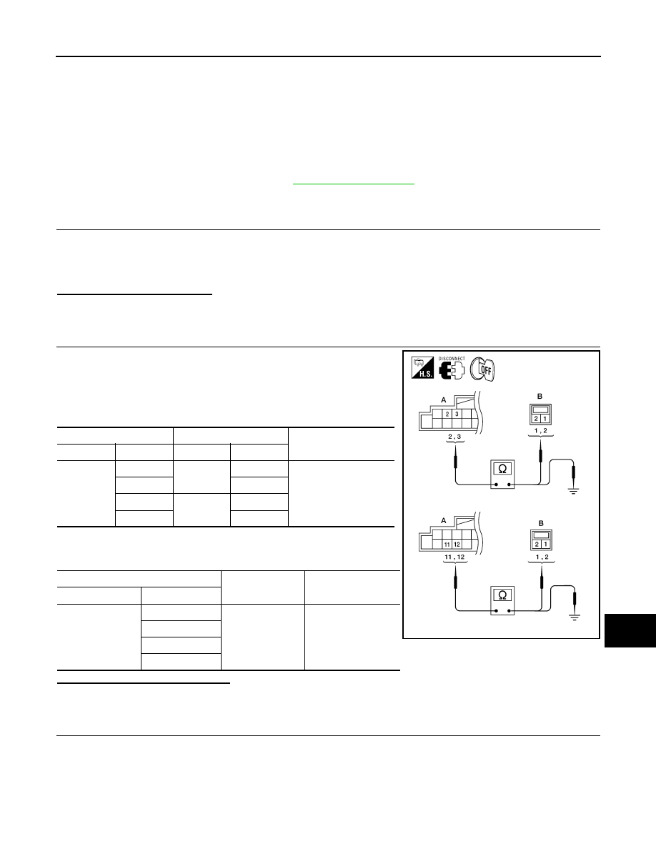
HARNESS CHECK
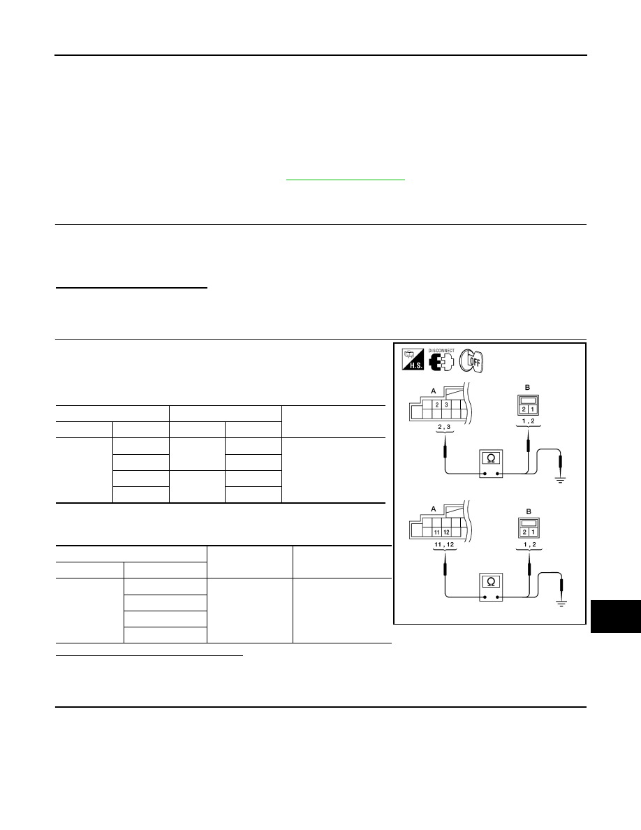
1. Disconnect AV control unit connector M131 and suspect
speaker connector.
2. Check continuity between AV control unit harness connector
M131 (A) terminal and suspect speaker harness connector (B)
terminal.
3. Check continuity between AV control unit harness connector
M131 (A) terminal and ground.
Are continuity results as specified?
YES
>> GO TO 3
NO
>> Repair harness or connector.
3.
FRONT SPEAKER SIGNAL CHECK
A
B
Continuity
Connector
Terminal
Connector
Terminal
M131
2
D12
1
Yes
3
2
11
D112
1
12
2
A
—
Continuity
Connector
Terminal
M131
2
Ground
No
3
11
12
AWNIA0031ZZ
August 2012
2012 Pathfinder
AV-78
< DTC/CIRCUIT DIAGNOSIS >
[MID AUDIO]
FRONT DOOR SPEAKER
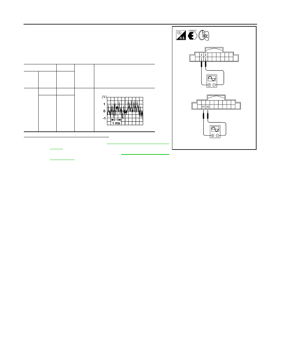
1. Connect AV control unit connector M131 and front speaker con-
nector.
2. Turn ignition switch to ACC.
3. Push “POWER” switch.
4. Check the signal between AV control unit harness connector
M131 terminals with CONSULT or oscilloscope.
Is the audio signal voltage as specified?
YES
>> Replace speaker. Refer to
.
NO
>> Replace AV control unit. Refer to
(+)
(-)
Condi-
tion
Reference signal
Con-
nec-
tor
Termi-
nal
Termi-
nal
M131
2
3
Receive
audio
signal
11
12
AWNIA0032ZZ
SKIA0177E
August 2012
2012 Pathfinder
AV
FRONT TWEETER
AV-79
< DTC/CIRCUIT DIAGNOSIS >
[MID AUDIO]
C
D
E
F
G
H
I
J
K
L
M
B
A
O
P
FRONT TWEETER
Description
INFOID:0000000007347650
The AV control unit sends audio signals to the front tweeters using the front tweeter circuits.
Diagnosis Procedure
INFOID:0000000007347651
Regarding Wiring Diagram information, refer to
1.
CONNECTOR CHECK
Check the AV control unit and speaker connectors for the following:
• Proper connection
• Damage
• Disconnected or loose terminals
Is the inspection result normal?
YES
>> GO TO 2.
NO
>> Repair the terminal and connector.
2.
HARNESS CHECK
1. Disconnect AV control unit connector M131 and suspect front
tweeter connector.
2. Check continuity between AV control unit harness connector
M131 (A) and suspect front tweeter harness connector (B).
3. Check continuity between AV control unit harness connector
M131 (A) and ground.
Are the continuity results as specified?
YES
>> GO TO 3
NO
>> Repair harness or connector.
3.
FRONT TWEETER SIGNAL CHECK
A
B
Continuity
Connector
Terminal
Connector
Terminal
M131
2
M109
1
Yes
3
2
11
M111
1
12
2
A
—
Continuity
Connector
Terminal
M131
2
Ground
No
3
11
12
AWNIA0031ZZ
August 2012
2012 Pathfinder
AV-80
< DTC/CIRCUIT DIAGNOSIS >
[MID AUDIO]
FRONT TWEETER
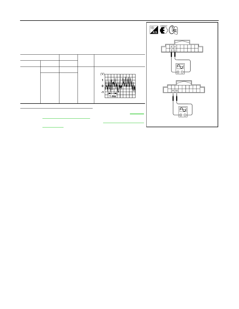
1. Connect AV control unit connector M131 and front tweeter con-
nector.
2. Turn ignition switch to ACC.
3. Push “POWER” switch.
4. Check the signal between AV control unit harness connector
M131 terminals with CONSULT or oscilloscope.
Is the audio signal voltage as specified?
YES
>> Replace the suspect front tweeter. Refer to
.
NO
>> Replace AV control unit. Refer to
(+)
(-)
Condi-
tion
Reference signal
Connector
Terminal
Terminal
M131
2
3
Receive
audio
signal
11
12
AWNIA0032ZZ
SKIA0177E
August 2012
2012 Pathfinder

AV
REAR DOOR SPEAKER
AV-81
< DTC/CIRCUIT DIAGNOSIS >
[MID AUDIO]
C
D
E
F
G
H
I
J
K
L
M
B
A
O
P
REAR DOOR SPEAKER
Description
INFOID:0000000007347652
The AV control unit sends audio signals to the rear speakers using the rear speaker circuits.
Diagnosis Procedure
INFOID:0000000007347653
Regarding Wiring Diagram information, refer to
1.
CONNECTOR CHECK
Check the AV control unit and speaker connectors for the following:
• Proper connection
• Damage
• Disconnected or loose terminals
Is the inspection result normal?
YES
>> GO TO 2.
NO
>> Repair the terminal and connector.
2.
HARNESS CHECK
1. Disconnect AV control unit connector M131 and suspect rear
speaker connector.
2. Check continuity between AV control unit harness connector
M131 (A) and suspect rear speaker harness connector (B).
3. Check continuity between AV control unit harness connector
M131 (A) and ground.
Are the continuity results as specified?
YES
>> GO TO 3
NO
>> Repair harness or connector.
3.
REAR SPEAKER SIGNAL CHECK
A B
Continuity
Connector
Terminal
Connector
Terminal
M131
4
D209
1
Yes
5
2
13
D309
1
14
2
A
—
Continuity
Connector
Terminal
M131
4
Ground
No
5
13
14
AWNIA0033ZZ
August 2012
2012 Pathfinder
Нет комментариевНе стесняйтесь поделиться с нами вашим ценным мнением.
Текст