Nissan Pathfinder (2012 year). Instruction — part 447
LAN-4
< SYSTEM DESCRIPTION >
[CAN FUNDAMENTAL]
CAN COMMUNICATION SYSTEM
SYSTEM DESCRIPTION
CAN COMMUNICATION SYSTEM
System Description
INFOID:0000000007801295
• CAN communication is a multiplex communication system. This enables the system to transmit and receive
large quantities of data at high speed by connecting control units with two communication lines (CAN-H and
CAN-L).
• Control units on the CAN network transmit signals using the CAN communication control circuit. They
receive only necessary signals from other control units to operate various functions.
• CAN communication lines adopt twisted-pair line style (two lines twisted) for noise immunity.
System Diagram
INFOID:0000000007801296
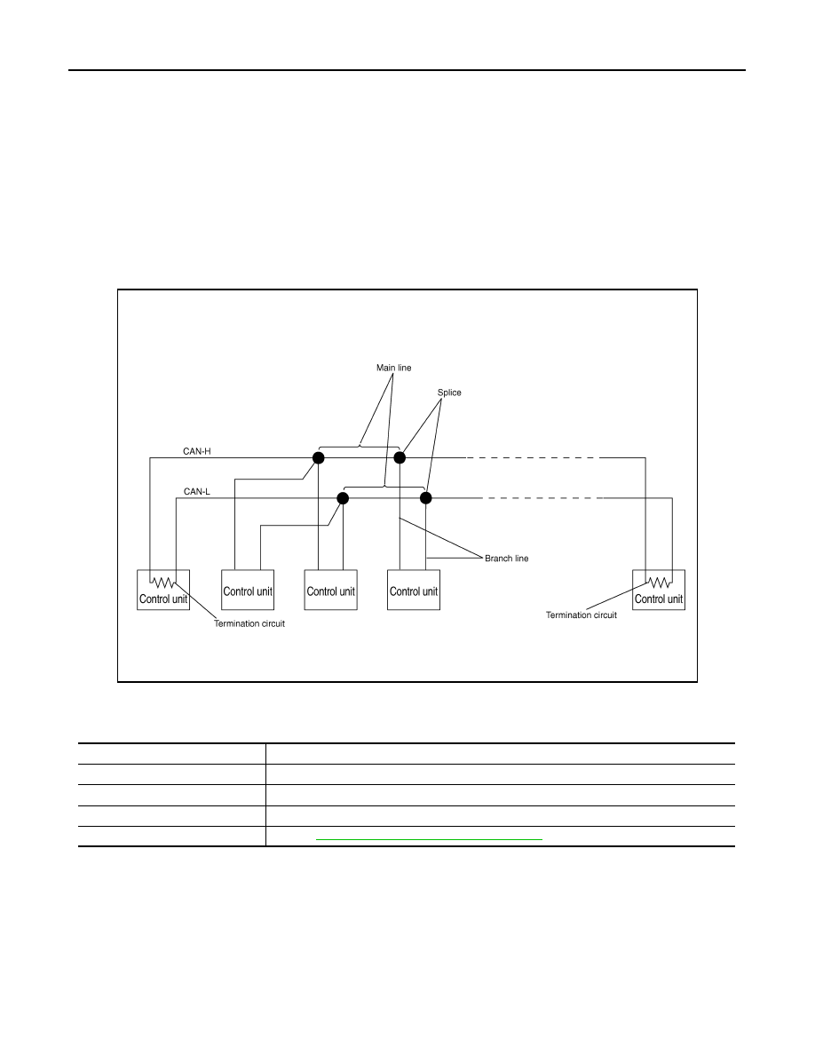
Each control unit passes an electric current to the termination circuits when transmitting CAN communication
signal. The termination circuits produce an electrical potential difference between CAN-H and CAN-L. CAN
communication system transmits and receives CAN communication signals by the potential difference.
SKIB8887E
Component
Description
Main line
CAN communication line between splices
Branch line
CAN communication line between splice and a control unit
Splice
A point connecting a branch line with a main line
Termination circuit
LAN-5, "CAN Communication Control Circuit"
.
August 2012
2012 Pathfinder
LAN
CAN COMMUNICATION SYSTEM
LAN-5
< SYSTEM DESCRIPTION >
[CAN FUNDAMENTAL]
C
D
E
F
G
H
I
J
K
L
B
A
O
P
N
CAN Communication Control Circuit
INFOID:0000000007801297
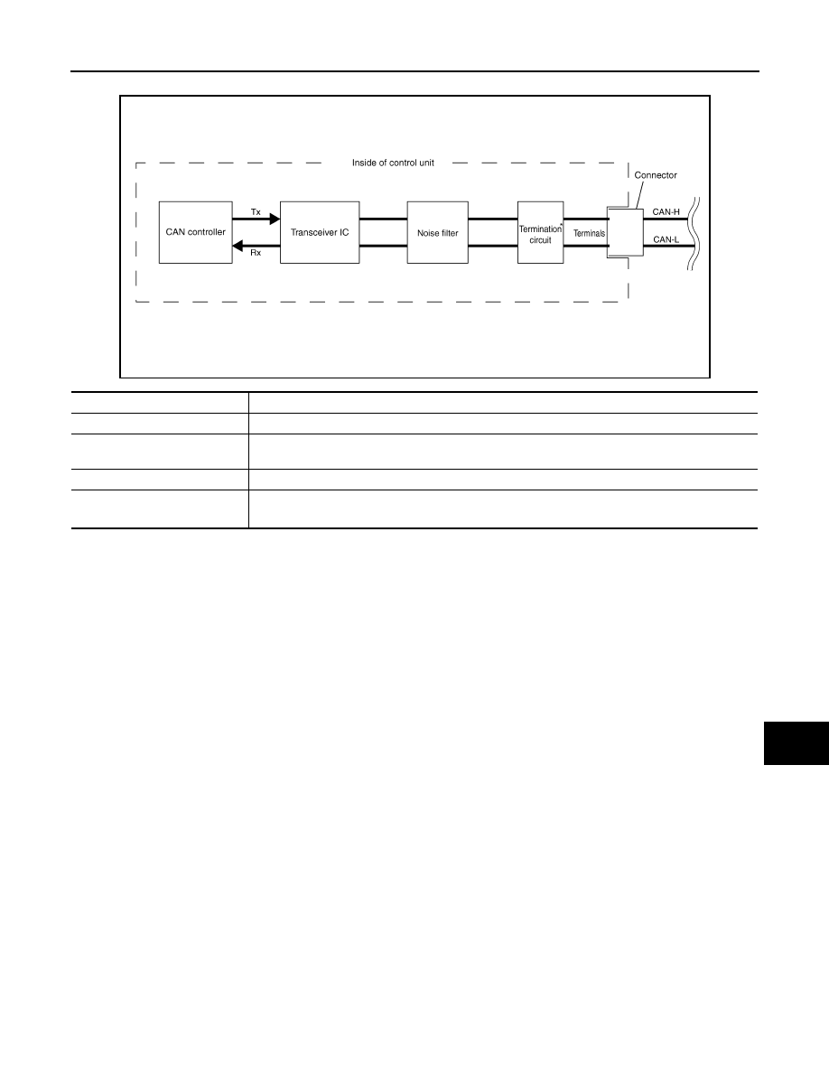
*: These are the only control units wired with both ends of CAN communication system.
SKIB8713E
Component
System description
CAN controller
It controls CAN communication signal transmission and reception, error detection, etc.
Transceiver IC
It converts digital signal into CAN communication signal, and CAN communication signal into digital
signal.
Noise filter
It eliminates noise of CAN communication signal.
Termination circuit
*
(Resistance of approx. 120
Ω
)
It produces potential difference.
August 2012
2012 Pathfinder
LAN-6
< SYSTEM DESCRIPTION >
[CAN FUNDAMENTAL]
DIAG ON CAN
DIAG ON CAN
Description
INFOID:0000000007801298
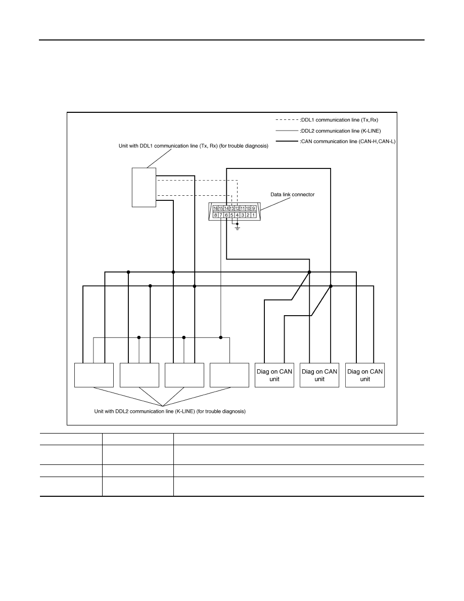
“Diag on CAN” is a diagnosis using CAN communication instead of previous DDL1 and DDL2 communication
lines, between control units and diagnosis unit.
System Diagram
INFOID:0000000007801299
SKIB8714E
Name
Harness
Description
DDL1
Tx
Rx
It is used for trouble diagnosis. (CAN-H and CAN-L are used for controlling)
DDL2
K-LINE
It is used for trouble diagnosis. (CAN-H and CAN-L are used for controlling)
Diag on CAN
CAN-H
CAN-L
It is used for trouble diagnosis and control.
August 2012
2012 Pathfinder
LAN
TROUBLE DIAGNOSIS
LAN-7
< SYSTEM DESCRIPTION >
[CAN FUNDAMENTAL]
C
D
E
F
G
H
I
J
K
L
B
A
O
P
N
TROUBLE DIAGNOSIS
Condition of Error Detection
INFOID:0000000007801300
DTC (e.g. U1000 and U1001) of CAN communication is indicated on SELF-DIAG RESULTS on CONSULT if a
CAN communication signal is not transmitted or received between units for 2 seconds or more.
CAN COMMUNICATION SYSTEM ERROR
• CAN communication line open (CAN-H, CAN-L, or both)
• CAN communication line short (ground, between CAN communication lines, other harnesses)
• Error of CAN communication control circuit of the unit connected to CAN communication line
WHEN DTC OF CAN COMMUNICATION IS INDICATED EVEN THOUGH CAN COMMUNICATION
SYSTEM IS NORMAL
• Removal/installation of parts: Error may be detected when removing and installing CAN communication unit
and related parts while turning the ignition switch ON. (A DTC except for CAN communication may be
detected.)
• Fuse blown out (removed): CAN communication of the unit may cease.
• Voltage drop: Error may be detected if voltage drops due to discharged battery when turning the ignition
switch ON (Depending on the control unit which carries out CAN communication).
• Error may be detected if the power supply circuit of the control unit, which carries out CAN communication,
malfunctions (Depending on the control unit which carries out CAN communication).
• Error may be detected if reprogramming is not completed normally.
CAUTION:
CAN communication system is normal if DTC of CAN communication is indicated on SELF-DIAG
RESULTS of CONSULT under the above conditions. Erase the memory of the self-diagnosis of each
unit.
Symptom When Error Occurs in CAN Communication System
INFOID:0000000007801301
In CAN communication system, multiple units mutually transmit and receive signals. Each unit cannot transmit
and receive signals if any error occurs on CAN communication line. Under this condition, multiple control units
related to the root cause malfunction or go into fail-safe mode.
ERROR EXAMPLE
NOTE:
• Each vehicle differs in symptom of each unit under fail-safe mode and CAN communication line wiring.
• Refer to
for the unit abbreviation.
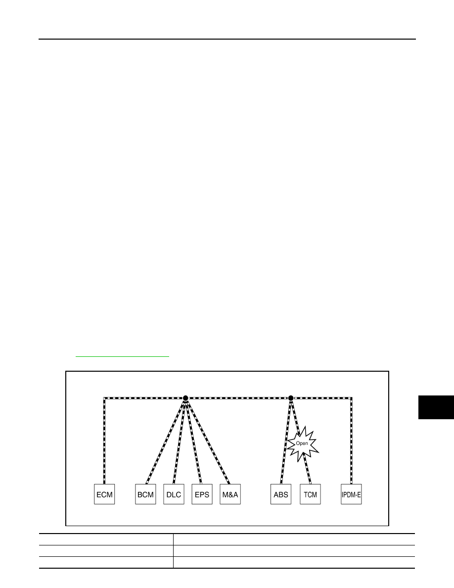
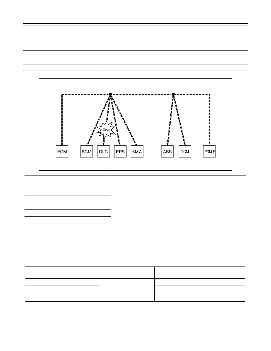
Example: TCM branch line open circuit
SKIB8738E
Unit name
Symptom
ECM
Engine torque limiting is affected, and shift harshness increases.
BCM
Reverse warning chime does not sound.
August 2012
2012 Pathfinder
LAN-8
< SYSTEM DESCRIPTION >
[CAN FUNDAMENTAL]
TROUBLE DIAGNOSIS
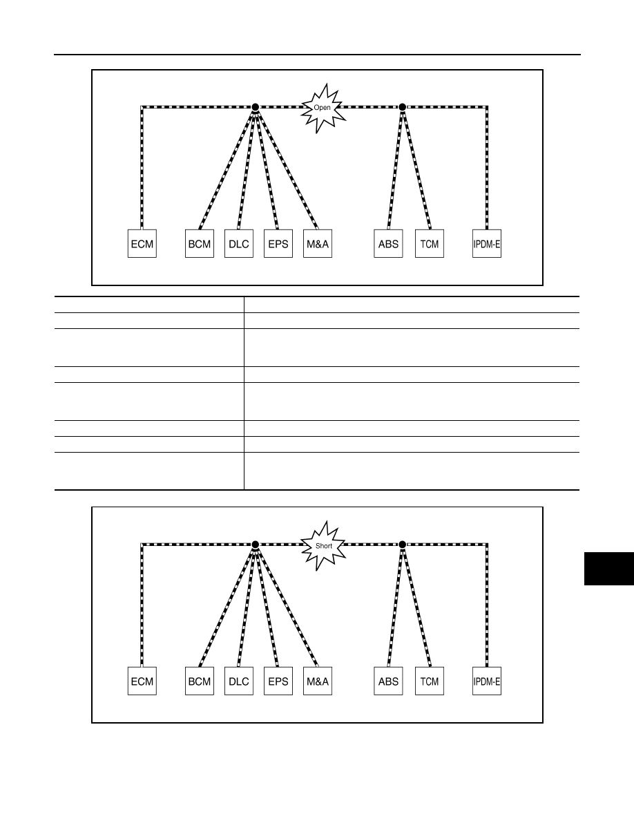
Example: Data link connector branch line open circuit
NOTE:
• When data link connector branch line is open, transmission and reception of CAN communication signals
are not affected. Therefore, no symptoms occur. However, be sure to repair malfunctioning circuit.
• When data link connector branch line is open, “system” displayed on the CONSULT “ALL DTC” may be the
same as when the CAN communication line has short-circuit. However, symptoms differ depending on the
case. See below chart for the differences.
EPS control unit
Normal operation.
Combination meter
• Shift position indicator and OD OFF indicator turn OFF.
• Warning lamps turn ON.
ABS actuator and electric unit (control unit)
Normal operation.
TCM
No impact on operation.
IPDM E/R
Normal operation.
Unit name
Symptom
SKIB8739E
Unit name
Symptom
ECM
Normal operation.
BCM
EPS control unit
Combination meter
ABS actuator and electric unit (control unit)
TCM
IPDM E/R
“System” on the “ALL DTC”
(CONSULT)
Difference of symptom
Data link connector branch line open circuit
All Diag on CAN units are not
indicated.
Normal operation.
CAN-H, CAN-L harness short-circuit
Most of the units which are connected to the CAN
communication system enter fail-safe mode or are
deactivated.
August 2012
2012 Pathfinder
LAN
TROUBLE DIAGNOSIS
LAN-9
< SYSTEM DESCRIPTION >
[CAN FUNDAMENTAL]
C
D
E
F
G
H
I
J
K
L
B
A
O
P
N
Example: Main Line Between Data Link Connector and ABS Actuator and Electric Unit (Control Unit) Open Circuit
Example: CAN-H, CAN-L Harness Short Circuit
SKIB8740E
Unit name
Symptom
ECM
Engine torque limiting is affected, and shift harshness increases.
BCM
• Reverse warning chime does not sound.
• The front wiper moves under continuous operation mode even though the front wip-
er switch being in the intermittent position.
EPS control unit
The steering effort increases.
Combination meter
• The shift position indicator and OD OFF indicator turn OFF.
• The speedometer is inoperative.
• The odo/trip meter stops.
ABS actuator and electric unit (control unit)
Normal operation.
TCM
No impact on operation.
IPDM E/R
When the ignition switch is ON,
• The headlamps (Lo) turn ON.
• The cooling fan continues to rotate.
SKIB8741E
August 2012
2012 Pathfinder

LAN-10
< SYSTEM DESCRIPTION >
[CAN FUNDAMENTAL]
TROUBLE DIAGNOSIS
Self-Diagnosis
INFOID:0000000007801302
If communication signals cannot be transmitted or received among units communicating via CAN communica-
tion line, CAN communication-related DTC is displayed on the CONSULT “Self Diagnostic Result” screen.
NOTE:
The following table shows examples of CAN communication-related DTC. For other DTC, refer to the applica-
ble sections.
CAN Diagnostic Support Monitor
INFOID:0000000007801303
CONSULT and CAN diagnostic support monitor (on-board diagnosis function) are used for detecting root
cause.
MONITOR ITEM (CONSULT)
Unit name
Symptom
ECM
• Engine torque limiting is affected, and shift harshness increases.
• Engine speed drops.
BCM
• Reverse warning chime does not sound.
• The front wiper moves under continuous operation mode even though the front
wiper switch being in the intermittent position.
• The room lamp does not turn ON.
• The engine does not start (if an error or malfunction occurs while turning the igni-
tion switch OFF.)
• The steering lock does not release (if an error or malfunction occurs while turning
the ignition switch OFF.)
EPS control unit
The steering effort increases.
Combination meter
• The tachometer and the speedometer do not move.
• Warning lamps turn ON.
• Indicator lamps do not turn ON.
ABS actuator and electric unit (control unit)
Normal operation.
TCM
No impact on operation.
IPDM E/R
When the ignition switch is ON,
• The headlamps (Lo) turn ON.
• The cooling fan continues to rotate.
DTC
Self-diagnosis item
(CONSULT indication)
DTC detection condition
Inspection/Action
U1000
CAN COMM CIRCUIT
ECM
When ECM is not transmitting or receiving
CAN communication signal of OBD (emission-
related diagnosis) for 2 seconds or more.
Start the inspection. Refer
to the applicable section
of the indicated control
unit.
Except
for ECM
When a control unit (except for ECM) is not
transmitting or receiving CAN communication
signal for 2 seconds or more.
U1001
CAN COMM CIRCUIT
When ECM is not transmitting or receiving CAN commu-
nication signal other than OBD (emission-related diagno-
sis) for 2 seconds or more.
U1002
SYSTEM COMM
When a control unit is not transmitting or receiving CAN
communication signal for 2 seconds or less.
U1010
CONTROL UNIT(CAN)
When an error is detected during the initial diagnosis for
CAN controller of each control unit.
Replace the control unit
indicating “U1010”.
August 2012
2012 Pathfinder
LA N
TROUBLE DIAGNOSIS
LAN-11
< SYSTEM DESCRIPTION >
[CAN FUNDAMENTAL]
C
D
E
F
G
H
I
J
K
L
B
A
O
P
N
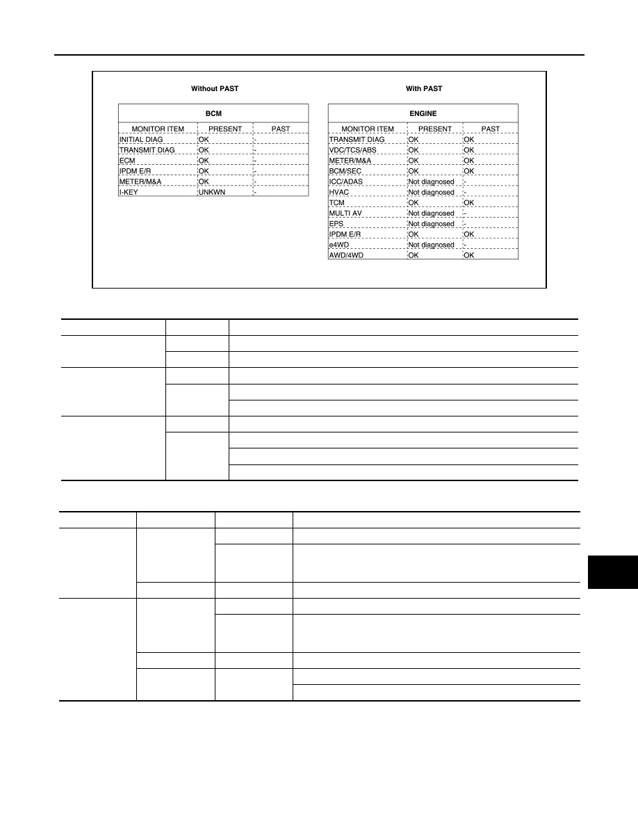
Example: CAN DIAG SUPPORT MNTR indication
Without PAST
With PAST
MONITOR ITEM (ON-BOARD DIAGNOSIS)
NOTE:
For some models, CAN communication diagnosis result is received from the vehicle monitor. (CONSULT is
not available.)
JSMIA0812GB
Item
PRESENT
Description
Initial diagnosis
OK
Normal at present
NG
Control unit error (Except for some control units)
Transmission diagnosis
OK
Normal at present
UNKWN
Unable to transmit signals for 2 seconds or more.
Diagnosis not performed
Control unit name
(Reception diagnosis)
OK
Normal at present
UNKWN
Unable to receive signals for 2 seconds or more.
Diagnosis not performed
No control unit for receiving signals. (No applicable optional parts)
Item
PRESENT
PAST
Description
Transmission di-
agnosis
OK
OK
Normal at present and in the past
1 – 39
Normal at present, but unable to transmit signals for 2 seconds or more
in the past. (The number indicates the number of ignition switch cycles
from OFF to ON.)
UNKWN
0
Unable to transmit signals for 2 seconds or more at present.
Control unit
name
(Reception diag-
nosis)
OK
OK
Normal at present and in the past
1 – 39
Normal at present, but unable to receive signals for 2 seconds or more
in the past. (The number indicates the number of ignition switch cycles
from OFF to ON.)
UNKWN
0
Unable to receive signals for 2 seconds or more at present.
Not diagnosed
–
Diagnosis not performed.
No control unit for receiving signals. (No applicable optional parts)
August 2012
2012 Pathfinder
Нет комментариевНе стесняйтесь поделиться с нами вашим ценным мнением.
Текст