Nissan Pathfinder (2012 year). Instruction — part 127
ENGINE COOLANT
CO-13
< PERIODIC MAINTENANCE >
[VQ40DE]
C
D
E
F
G
H
I
J
K
L
M
A
CO
N
P
O
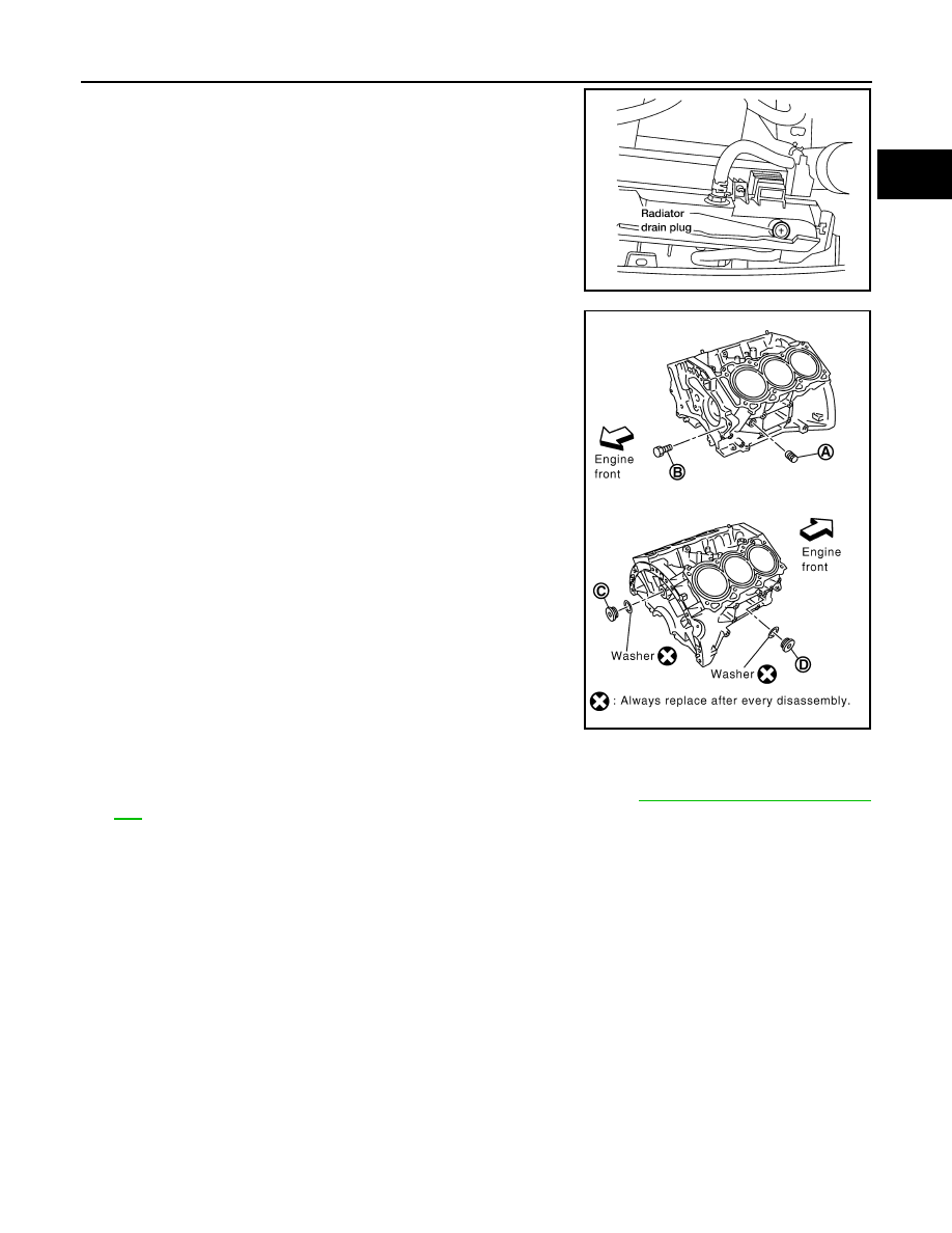
3. Open the radiator drain plug at the bottom of the radiator, and
remove the reservoir cap. This is the only step required when
partially draining the cooling system (radiator only).
CAUTION:
• Perform this step when the engine is cold.
• Do not to allow the coolant to contact the drive belts.
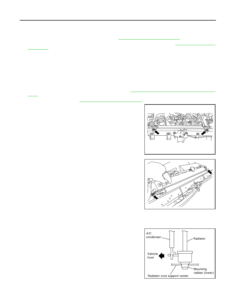
4. When draining all of the coolant in the system for engine
removal or repair, it is necessary to drain the cylinder block.
Remove the cylinder block drain plugs (A), (B), (C), (D) and
block heater, (if equipped), to drain the cylinder block as shown.
CAUTION:
Do not reuse copper sealing washers.
NOTE:
For Canada, the (D) cylinder block drain plug as shown, is not a
cylinder block drain plug but a block heater.
5. Remove the reservoir tank to drain the engine coolant, then clean the reservoir tank before installing it.
6. Check the drained coolant for contaminants such as rust, corrosion or discoloration.
If the coolant is contaminated, flush the engine cooling system. Refer to
.
REFILLING ENGINE COOLANT
LLIA0070E
WLIA0020E
August 2012
2012 Pathfinder
CO-14
< PERIODIC MAINTENANCE >
[VQ40DE]
ENGINE COOLANT
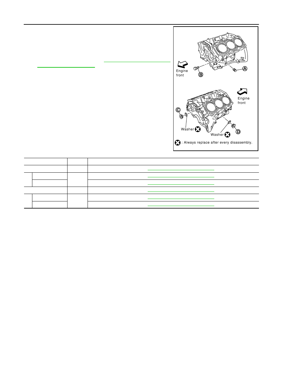
1. Close the radiator drain plug. Install the reservoir tank, cylinder
block drain plugs (A), (B), (C), (D) and block heater, (if
equipped).
• The radiator must be completely empty of coolant and water.
• Apply sealant to the threads of the cylinder block drain plugs
(A), (B), (C), (D). Use Genuine High Performance Thread
Sealant or equivalent. Refer to
.
CAUTION:
Do not reuse copper sealing washers.
Block Plug and Block Heater Installation
2. Set the vehicle heater controls to the full HOT and heater ON position. Turn the vehicle ignition ON with
the engine OFF as necessary to activate the heater mode.
3. Remove the vented reservoir cap and replace it with a non-vented reservoir cap before filling the cooling
system.
WLIA0020E
Part
Washer
Tightening Torque
A
No
Refer to
EM-105, "Disassembly and Assembly"
B
Reuse
No
Refer to
EM-105, "Disassembly and Assembly"
New
Refer to
EM-105, "Disassembly and Assembly"
C
Yes
Refer to
EM-105, "Disassembly and Assembly"
D
Plug
Yes
Refer to
EM-105, "Disassembly and Assembly"
Block heater
Refer to
EM-105, "Disassembly and Assembly"
August 2012
2012 Pathfinder
ENGINE COOLANT
CO-15
< PERIODIC MAINTENANCE >
[VQ40DE]
C
D
E
F
G
H
I
J
K
L
M
A
CO
N
P
O
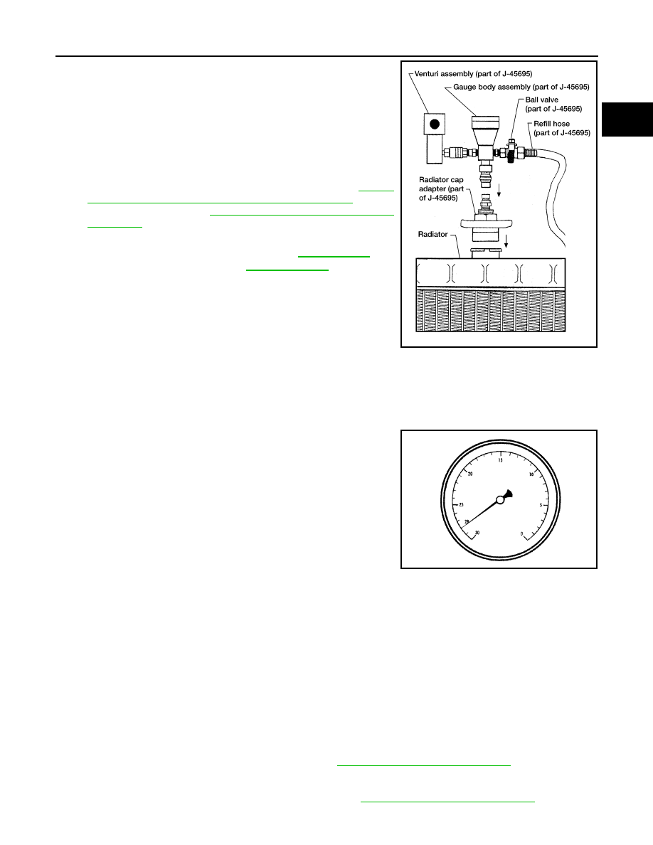
4. Install the Tool by installing the radiator cap adapter onto the
radiator neck opening. Then attach the gauge body assembly
with the refill tube and the venturi assembly to the radiator cap
adapter.
5. Insert the refill hose into the coolant mixture container that is
placed at floor level. Make sure the ball valve is in the closed
position.
•
Use recommended coolant or equivalent. Refer to
"FOR USA AND CANADA : Fluids and Lubricants"
(United
States and Canada) or
MA-20, "FOR MEXICO : Fluids and
(Mexico).
6. Install an air hose to the venturi assembly, the air pressure must
be within specification.
CAUTION:
The compressed air supply must be equipped with an air dryer.
7. The vacuum gauge will begin to rise and there will be an audible hissing noise. During this process open
the ball valve on the refill hose slightly. Rising coolant will be visible in the refill hose. After the refill hose is
full of coolant, close the ball valve. This will purge air trapped in the refill hose.
8. Continue to draw the vacuum until the gauge reaches 28 inches
of vacuum. The gauge may not reach 28 inches in high altitude
locations. Refer to the following table for expected vacuum read-
ings.
9. When the vacuum gauge has reached the specified amount, disconnect the air hose and wait 20 seconds
to see if the system loses vacuum. If the vacuum level drops, perform necessary repairs to the system
and repeat steps 6 - 8 to bring the vacuum to the specified amount. Recheck for leaks.
10. Place the coolant container (with the refill hose inserted) at the same level as the top of the radiator. Then
open the ball valve on the refill hose so the coolant will be drawn up to fill the cooling system. The cooling
system is full when the vacuum gauge reads zero.
CAUTION:
Do not allow the coolant container to get too low when filling, to avoid air from being drawn into
the cooling system.
11. Remove the Tool from the radiator neck opening and install the radiator cap.
12. Remove the non-vented reservoir cap.
13. Fill the cooling system reservoir tank to the specified level. Run the engine to warm up the cooling system
and top up the system as necessary before installing the vented reservoir cap.
14. Install the engine under cover or skid plate. Refer to
EXT-15, "Removal and Installation"
FLUSHING COOLING SYSTEM
1. Drain the water from the engine cooling system. Refer to
CO-12, "Changing Engine Coolant"
.
Tool number
: KV991J0070 (J-45695)
Cooling system capacity
(with reservoir)
: Refer to
Compressed air
supply pressure
: 549 - 824 kPa (5.6 - 8.4 kg/cm
2
,
80 - 119 psi)
LLIA0058E
Altitude above sea level
Vacuum gauge reading
0 - 100 m (328 ft)
: 28 inches of vacuum
300 m (984 ft)
: 27 inches of vacuum
500 m (1,641 ft)
: 26 inches of vacuum
1,000 m (3,281 ft)
: 24 - 25 inches of vacuum
LLIA0057E
August 2012
2012 Pathfinder
CO-16
< PERIODIC MAINTENANCE >
[VQ40DE]
ENGINE COOLANT
2. Fill the radiator and the reservoir tank (to the “MAX” line), with water. Reinstall the radiator cap and leave
the vented reservoir cap off.
3. Run the engine until it reaches normal operating temperature.
4. Press the engine accelerator two or three times under no-load.
5. Stop the engine and wait until it cools down.
6. Drain the water from the engine cooling system. Refer to
CO-12, "Changing Engine Coolant"
.
7. Repeat steps 2 through 6 until clear water begins to drain from the radiator.
August 2012
2012 Pathfinder
RADIATOR
CO-17
< REMOVAL AND INSTALLATION >
[VQ40DE]
C
D
E
F
G
H
I
J
K
L
M
A
CO
N
P
O
REMOVAL AND INSTALLATION
RADIATOR
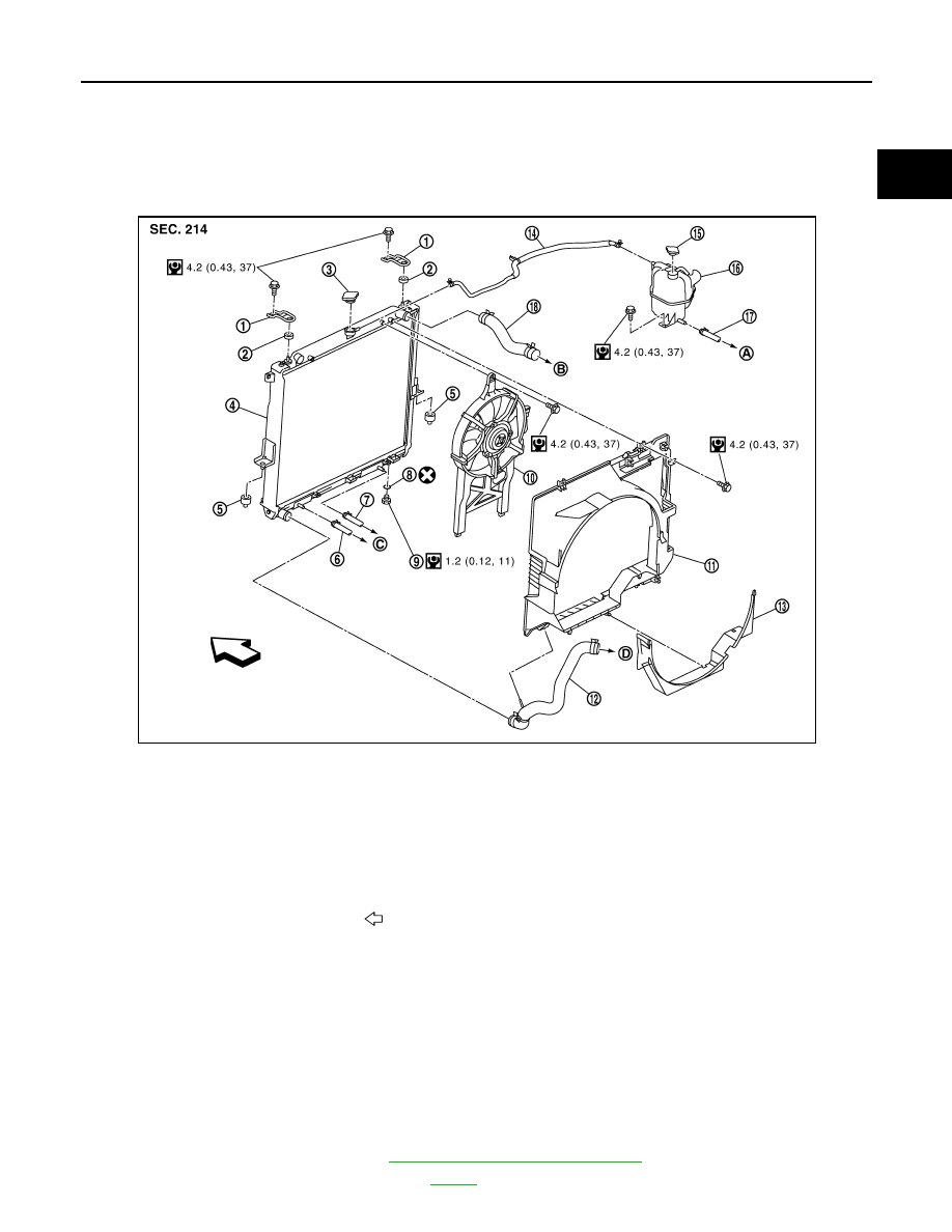
Exploded View
INFOID:0000000007357909
Removal and Installation
INFOID:0000000007357910
WARNING:
Never remove the radiator cap when the engine is hot. Serious burns could occur from high pressure
engine coolant escaping from the radiator. Wrap a thick cloth around the cap. Slowly turn it a quarter
of a turn to release built-up pressure. Carefully remove radiator cap by turning it all the way.
NOTE:
When removing components such as hoses, tubes/lines, etc., cap or plug openings to prevent fluid from spill-
ing.
REMOVAL
1. Remove engine under cover. Refer to
EXT-15, "Removal and Installation"
2. Drain engine coolant from radiator. Refer to
.
1.
Upper mount bracket
2.
Mounting rubber (upper)
3.
Radiator cap
4.
Radiator
5.
Mounting rubber (lower)
6.
A/T fluid cooler hose
7.
A/T fluid cooler hose
8.
O-ring
9.
Drain plug
10. Cooling fan assembly
11. Radiator shroud (upper)
12. Radiator hose (lower)
13. Radiator shroud (lower)
14. Reservoir tank hose
15. Reservoir tank cap
16. Reservoir tank
17. Water hose
18. Radiator hose (upper)
A.
To heater return tube
B.
To water pipe
C.
To A/T cooler tube
D.
To water inlet and thermostat assembly
Vehicle front
AWBIA1010GB
August 2012
2012 Pathfinder
CO-18
< REMOVAL AND INSTALLATION >
[VQ40DE]
RADIATOR
CAUTION:
• Perform this step when engine is cold.
• Do not spill engine coolant on drive belts.
3. Remove engine room cover (if equipped). Refer to
EM-25, "Removal and Installation"
.
4. Remove air duct and resonator assembly and air cleaner case (upper). Refer to
.
5. Remove reservoir tank hose.
6. Remove radiator hoses (upper and lower).
CAUTION:
Be careful not to allow engine coolant to contact drive belts.
7. Disconnect A/T fluid cooler hoses.
8. Remove radiator shroud (lower).
9. Remove radiator shroud (upper).
10. Remove engine cooling fan (Motor driven type). Refer to
CO-21, "Removal and Installation (Motor driven
11. Remove front grille. Refer to
EXT-20, "Removal and Installation"
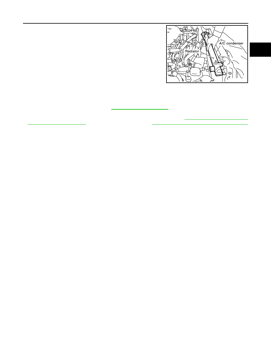
12. Remove the upper mount bracket bolts.
13. Remove the two A/C condenser bolts.
14. Remove radiator as follows:
CAUTION:
Do not damage or scratch A/C condenser and radiator core when removing.
a. Lift and pull radiator rearward to disengage rubber mounting
(lower) from radiator core support center.
CAUTION:
Because A/C condenser is attached to the front-lower por-
tion of radiator, moving it in the rear direction should be at a
minimum.
LBIA0419E
LBIA0421E
PBIC1936E
August 2012
2012 Pathfinder
RADIATOR
CO-19
< REMOVAL AND INSTALLATION >
[VQ40DE]
C
D
E
F
G
H
I
J
K
L
M
A
CO
N
P
O
b. Lift A/C condenser up and remove radiator after disengaging the
fitting at front-bottom surface.
CAUTION:
Lifting A/C condenser should be minimum to prevent a load
to A/C piping.
c. After removing radiator, put A/C condenser on radiator core cen-
ter support and temporarily fasten it to prevent overloading the
A/C piping.
INSTALLATION
Installation is in the reverse order of removal.
INSPECTION AFTER INSTALLATION
• Check for engine coolant leaks. Refer to
• Start and warm up engine. Visually check for coolant and A/T fluid leaks. Repair as necessary.
• Check and adjust engine coolant level and A/T fluid (if equipped). Refer to
(United States and Canada) or
MA-20, "FOR MEXICO : Fluids and Lubricants"
(Mexico).
PBIC1054E
August 2012
2012 Pathfinder
CO-20
< REMOVAL AND INSTALLATION >
[VQ40DE]
ENGINE COOLING FAN
ENGINE COOLING FAN
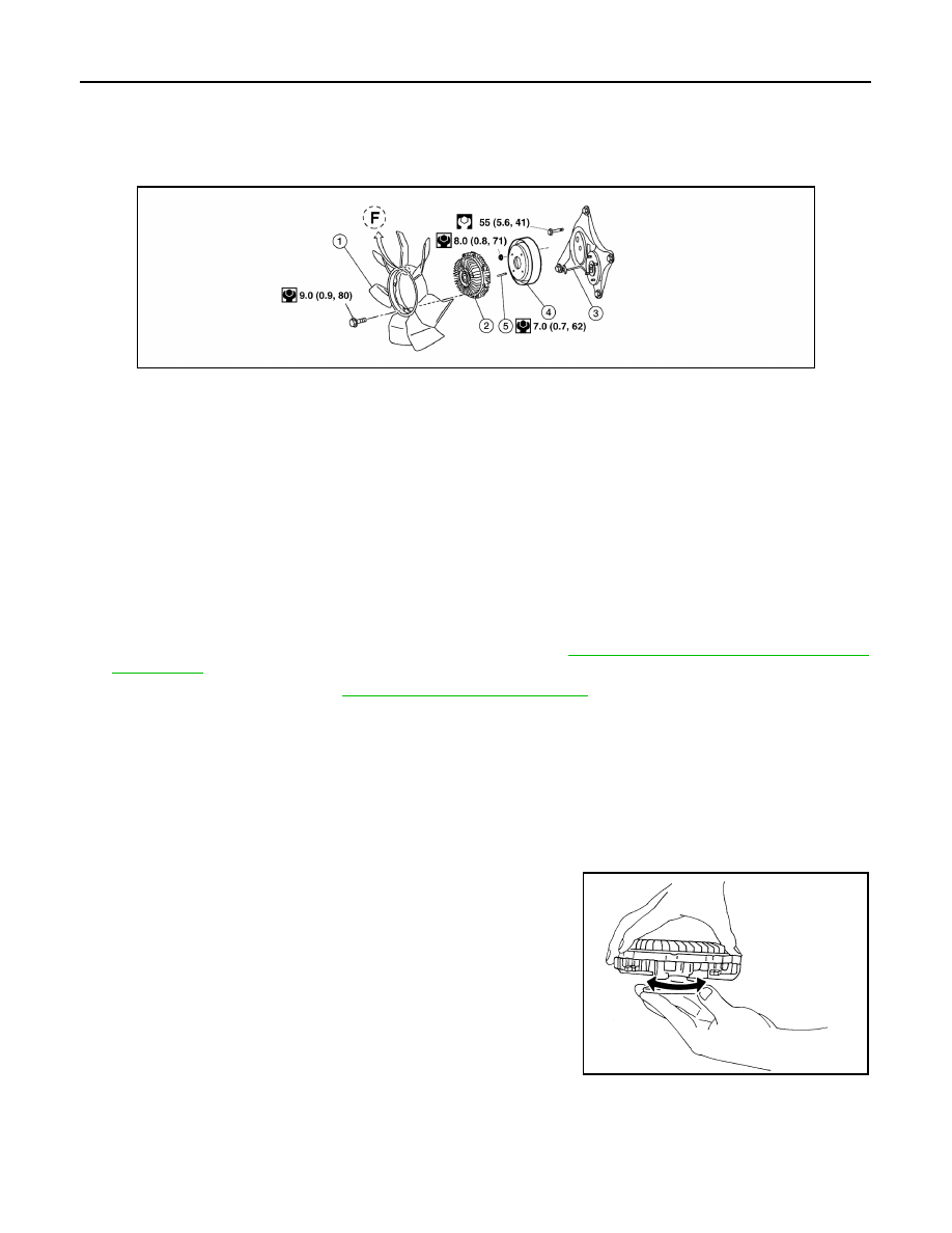
Exploded View
INFOID:0000000007357912
Crankshaft Driven Type
Removal and Installation (Crankshaft driven type)
INFOID:0000000007357913
WARNING:
Never remove the radiator cap when the engine is hot. Serious burns could occur from high pressure
engine coolant escaping from the radiator. Wrap a thick cloth around the cap. Slowly turn it a quarter
of a turn to release built-up pressure. Carefully remove radiator cap by turning it all the way.
NOTE:
When removing components such as hoses, tubes/lines, etc., cap or plug openings to prevent fluid from spill-
ing.
REMOVAL
1. Remove the engine cooling fan (Motor driven type). Refer to
CO-21, "Removal and Installation (Motor
2. Remove the drive belt. Refer to
EM-14, "Removal and Installation"
.
3. Remove the engine cooling fan.
4. Remove the fan coupling, if necessary.
5. Remove the cooling fan pulley, if necessary.
6. Remove the drive belt auto-tensioner, if necessary.
7. Remove the fan bracket, if necessary.
INSPECTION AFTER REMOVAL
Fan Coupling
• Inspect fan coupling for oil leaks and bimetal corrosion conditions.
• If there are concerns, replace the fan coupling.
Fan Bracket
AWBIA1124GB
1.
Cooling fan
2.
Fan coupling
3.
Fan bracket
4.
Cooling fan pulley
5.
Stud
F.
Front mark
SLC072
August 2012
2012 Pathfinder
Нет комментариевНе стесняйтесь поделиться с нами вашим ценным мнением.
Текст