Nissan Pathfinder (2012 year). Instruction — part 209
U1010 CONTROL UNIT (CAN)
DLN-237
< DTC/CIRCUIT DIAGNOSIS >
[TRANSFER: TX15B]
C
E
F
G
H
I
J
K
L
M
A
B
DLN
N
O
P
U1010 CONTROL UNIT (CAN)
Description
INFOID:0000000007357533
CAN (Controller Area Network) is a serial communication line for real time application. It is an on-vehicle mul-
tiplex communication line with high data communication speed and excellent error detection ability. Many elec-
tronic control units are equipped onto a vehicle, and each control unit shares information and links with other
control units during operation (not independent). In CAN communication, control units are connected with 2
communication lines (CAN-H line, CAN-L line) allowing a high rate of information transmission with less wiring.
Each control unit communicate data but selectively reads required data only.
DTC Logic
INFOID:0000000007357534
DTC DETECTION LOGIC
DTC CONFIRMATION PROCEDURE
1.
DTC REPRODUCTION PROCEDURE
With CONSULT
1. Turn the ignition switch ON.
2. Perform transfer control unit self-diagnosis. Refer to
DLN-202, "CONSULT Function (ALL MODE AWD/
Is DTC U1010 detected?
YES
>> Proceed to diagnosis procedure. Refer to
DLN-237, "Diagnosis Procedure"
.
NO
>> Inspection End.
Diagnosis Procedure
INFOID:0000000007357535
1.
CHECK TRANSFER CONTROL UNIT CONNECTOR
Check transfer control unit connectors for disconnection and deformation.
Is the inspection result normal?
YES
>> Replace transfer control unit. Refer to
DLN-278, "Removal and Installation"
NO
>> Repair or replace parts as necessary.
DTC
Display item
Malfunction detected condition
Possible cause
U1010
CONTROL UNIT (CAN)
Detecting error during the initial diagno-
sis of CAN controller of transfer control
unit.
Malfunction of transfer control unit
August 2012
2012 Pathfinder

DLN-238
< ECU DIAGNOSIS INFORMATION >
[TRANSFER: TX15B]
TRANSFER CONTROL UNIT
ECU DIAGNOSIS INFORMATION
TRANSFER CONTROL UNIT
Reference Value
INFOID:0000000007357536
VALUE ON THE DIAGNOSIS TOOL
CONSULT data monitor item
Monitored item [Unit]
Content
Condition
Display value
VHCL/S SEN·FR [km/h]
or [mph]
Wheel speed (Front wheel)
Vehicle stopped
0 km/h (0 mph)
Vehicle running
CAUTION:
Check air pressure of tire under standard condi-
tion.
Approximately
equal to the indica-
tion on speedome-
ter (Inside of
±
10%)
VHCL/S SEN·RR [km/h]
or [mph]
Wheel speed (Rear wheel)
Vehicle stopped
0 km/h (0 mph)
Vehicle running
CAUTION:
Check air pressure of tire under standard condi-
tion.
Approximately
equal to the indica-
tion on speedome-
ter (Inside of
±
10%)
ENGINE SPEED [rpm]
Engine speed
Engine stopped
(Engine speed: Less than 400 rpm)
0 rpm
Engine running
(Engine speed: 400 rpm or more)
Approximately
equal to the indica-
tion on tachometer
BATTERY VOLT [V]
Power supply voltage for
transfer control unit
Ignition switch: On
Battery voltage
2WD SWITCH [On/Off]
Input condition from 4WD
shift switch
4WD shift switch: 2WD
On
4WD shift switch: 4H and 4LO
Off
4H SWITCH [On/Off]
Input condition from 4WD
shift switch
4WD shift switch: 4H
On
4WD shift switch: 2WD and 4LO
Off
4L SWITCH [On/Off]
Input condition from 4WD
shift switch
4WD shift switch: 4LO
On
4WD shift switch: 2WD and 4H
Off
4L POSI SW [On/Off]
Condition of 4LO switch
• Vehicle stopped
• Engine running
• A/T selector lever “N”
position
• Brake pedal depressed
4WD shift switch: 4LO
On
Except the above
Off
ATP SWITCH [On/Off]
Condition of ATP switch
• Vehicle stopped
• Engine running
• A/T selector lever “N”
position
• Brake pedal depressed
4WD shift switch
: 4H to 4LO or 4LO to 4H
(While actuator motor is
operating.)
On
Except the above
Off
WAIT DETCT SW [On/
Off]
Condition of wait detection
switch
• Vehicle stopped
• Engine running
• A/T selector lever “N”
position
• Brake pedal depressed
4WD shift switch
: 4H and 4LO
On
4WD shift switch: 2WD
Off
4WD MODE [2H/4H/4L]
Control status of 4WD
(Output condition of 4WD
shift indicator lamp and
4LO indicator lamp)
4WD shift switch
(Engine running)
2WD
2H
4H
4H
4LO
4L
August 2012
2012 Pathfinder

TRANSFER CONTROL UNIT
DLN-239
< ECU DIAGNOSIS INFORMATION >
[TRANSFER: TX15B]
C
E
F
G
H
I
J
K
L
M
A
B
DLN
N
O
P
PHYSICAL VALUES
VHCL/S COMP [km/h] or
[mph]
Vehicle speed
Vehicle stopped
0 km/h (0 mph)
Vehicle running
CAUTION:
Check air pressure of tire under standard condi-
tion.
Approximately
equal to the indica-
tion on speedome-
ter (Inside of
±
10%)
SHIFT ACT 1 [On/Off]
Output condition to actua-
tor motor (clockwise)
• Vehicle stopped
• Engine running
• A/T selector lever “N”
position
• Brake pedal depressed
4WD shift switch
: 2WD to 4H or 4H to 4LO
or 2WD to 4LO
On
Except the above
Off
SHIFT AC MON1 [On/
Off]
Check signal for transfer
control unit signal output
• Vehicle stopped
• Engine running
• A/T selector lever “N”
position
• Brake pedal depressed
4WD shift switch
: 2WD to 4H or 4H to 4LO
or 2WD to 4LO
On
Except the above
Off
SHIFT ACT 2 [On/Off]
Output condition to actua-
tor motor (counterclock-
wise)
• Vehicle stopped
• Engine running
• A/T selector lever “N”
position
• Brake pedal depressed
4WD shift switch
: 4LO to 4H or 4H to 2WD
or 4LO to 2WD
On
Except the above
Off
SHIFT AC MON2 [On/
Off]
Check signal for transfer
control unit signal output
• Vehicle stopped
• Engine running
• A/T selector lever “N”
position
• Brake pedal depressed
4WD shift switch
: 4LO to 4H or 4H to 2WD
or 4LO to 2WD
On
Except the above
Off
SHIFT ACT/R MON [On/
Off]
Operating condition of ac-
tuator motor relay (integrat-
ed in transfer control unit)
• Vehicle stopped
• Engine running
• A/T selector lever “N”
position
• Brake pedal depressed
When 4WD shift switch is
operated
On
When 4WD shift switch is
not operated
Off
SHIFT POS SW1 [On/
Off]
Condition of actuator posi-
tion switch 1
• Vehicle stopped
• Engine running
• A/T selector lever “N”
position
• Brake pedal depressed
4WD shift switch: 2WD
and 4LO
On
4WD shift switch: 4H
Off
SHIFT POS SW2 [On/
Off]
Condition of actuator posi-
tion switch 2
4WD shift switch: 4LO
On
4WD shift switch: 2WD
and 4H
Off
SHIFT POS SW3 [On/
Off]
Condition of actuator posi-
tion switch 3
4WD shift switch: 2WD
and 4H
On
4WD shift switch: 4LO
Off
SHIFT POS SW4 [On/
Off]
Condition of actuator posi-
tion switch 4
4WD shift switch: 4H and
4LO
On
4WD shift switch: 2WD
Off
4WD FAIL LAMP [On/
Off]
4WD warning lamp condi-
tion
4WD warning lamp: On
On
4WD warning lamp: Off
Off
2WD IND [On/Off]
Rear indicator of 4WD shift
indicator lamp condition
Rear indicator of 4WD shift indicator lamp: On
On
Rear indicator of 4WD shift indicator lamp: Off
Off
4H IND [On/Off]
Front and center indicator
of 4WD shift indicator lamp
condition
Front and center indicator of 4WD shift indicator lamp
: On
On
Front and center indicator of 4WD shift indicator lamp
: Off
Off
4L IND [On/Off]
4LO indicator lamp condi-
tion
4LO indicator lamp: On
On
4LO indicator lamp: Off
Off
Monitored item [Unit]
Content
Condition
Display value
August 2012
2012 Pathfinder
DLN-240
< ECU DIAGNOSIS INFORMATION >
[TRANSFER: TX15B]
TRANSFER CONTROL UNIT
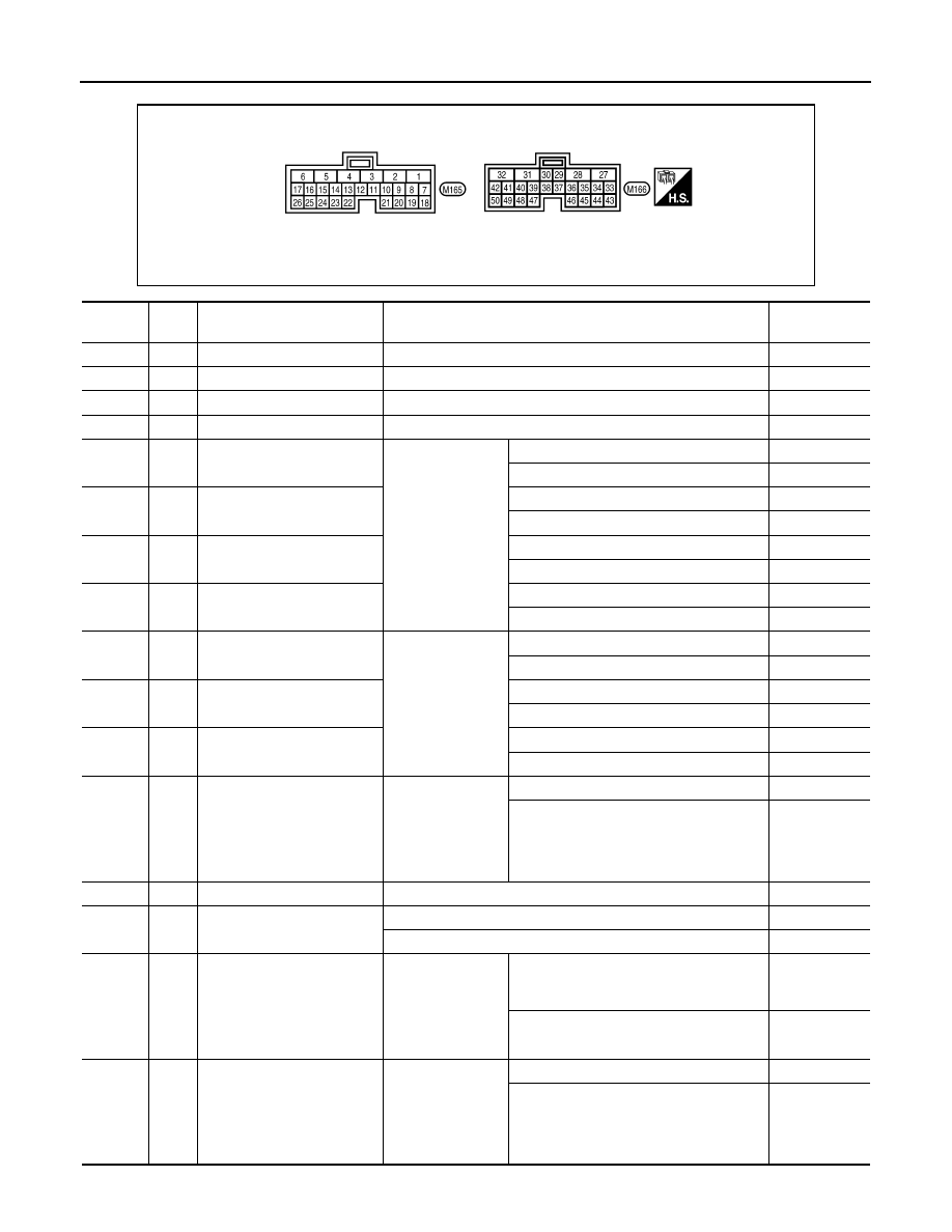
Terminal Layout
AWDIA0620ZZ
Terminal
Wire
color
Item
Condition
Data (Approx.)
1
L
CAN-H
–
–
2
P
CAN-L
–
–
3
SB
K-LINE (CONSULT signal)
–
–
6
B
Ground
Always
0V
10
LG
Actuator position switch 1
• Vehicle stopped
• Engine running
• A/T selector le-
ver “N” position
• Brake pedal de-
pressed
4WD shift switch: 2WD and 4LO
0V
4WD shift switch: 4H
Battery voltage
11
W
Actuator position switch 2
4WD shift switch: 4LO
0V
4WD shift switch: 2WD and 4H
Battery voltage
12
BR
Actuator position switch 3
4WD shift switch: 2WD and 4H
0V
4WD shift switch: 4LO
Battery voltage
13
L
Actuator position switch 4
4WD shift switch: 4H and 4LO
0V
4WD shift switch: 2WD
Battery voltage
14
G
4WD shift switch (2WD)
Ignition switch: ON
4WD shift switch: 2WD
Battery voltage
4WD shift switch: 4H and 4LO
0V
15
O
4WD shift switch (4H)
4WD shift switch: 4H
Battery voltage
4WD shift switch: 2WD and 4LO
0V
16
W
4WD shift switch (4LO)
4WD shift switch: 4LO
Battery voltage
4WD shift switch: 2WD and 4H
0V
17
O
Wait detection switch
• Vehicle stopped
• Engine running
• A/T selector le-
ver “N” position
• Brake pedal de-
pressed
4WD shift switch: 4H and 4LO
0V
4WD shift switch: 2WD
Battery voltage
18
B
Ground
Always
0V
19
R
Power supply
(Memory back-up)
Ignition switch: ON
Battery voltage
Ignition switch: OFF
Battery voltage
23
R
ATP switch
• Vehicle stopped
• Engine running
• A/T selector le-
ver “N”
• Brake pedal de-
pressed
4WD shift switch
: 4H to 4LO or 4LO to 4H
(While actuator motor is operating.)
0V
Except the above
Battery voltage
24
Y
4LO switch
• Vehicle stopped
• Engine running
• A/T selector le-
ver “N” position
• Brake pedal de-
pressed
4WD shift switch: 4LO
0V
Except the above
Battery voltage
August 2012
2012 Pathfinder

TRANSFER CONTROL UNIT
DLN-241
< ECU DIAGNOSIS INFORMATION >
[TRANSFER: TX15B]
C
E
F
G
H
I
J
K
L
M
A
B
DLN
N
O
P
25
W/G
Ignition switch monitor
Ignition switch: ON
Battery voltage
Ignition switch: OFF
0V
27
L
Actuator motor power supply
Ignition switch: ON
Battery voltage
Ignition switch: OFF (5 seconds after ignition switch is turned
OFF)
0V
28
SB
Actuator motor (+)
• Vehicle stopped
• Engine running
• A/T selector le-
ver “N” position
• Brake pedal de-
pressed
When 4WD shift switch is operated (while
actuator motor is operating)
Battery voltage
→
0V
When 4WD shift switch is not operated
0V
31
G
Actuator motor (-)
Always
0V
32
B
Ground
Always
0V
35
V
4WD shift indicator lamp
(Rear indicator)
Engine running
Rear indicator of 4WD shift indicator lamp
: ON
0V
Rear indicator of 4WD shift indicator lamp
: OFF
Battery voltage
36
BR
4WD shift indicator lamp
(Front and center indicator)
Front and center indicator of 4WD shift in-
dicator lamp: ON
0V
Front and center indicator of 4WD shift in-
dicator lamp: OFF
Battery voltage
37
O
4LO indicator lamp
4LO indicator lamp: ON
0V
4LO indicator lamp: OFF
Battery voltage
38
GR
4WD warning lamp
4WD warning lamp: ON
0V
4WD warning lamp: OFF
Battery voltage
39
LG
ATP warning lamp
• Vehicle stopped
• Engine running
• A/T selector le-
ver “P” position
• Brake pedal de-
pressed
4WD shift switch: 4H to 4LO or 4LO to 4H
(While actuator motor is operating.)
Battery voltage
Except the above
0V
40
V
Transfer shut off relay
Ignition switch: ON
0V
Ignition switch: OFF (5 seconds after ignition switch is turned
OFF)
Battery voltage
42
LG
Transfer shift high relay
• Vehicle stopped
• Engine running
• A/T selector le-
ver “N” position
• Brake pedal de-
pressed
4WD shift switch: 2WD to 4H or 4H to 4LO
or 2WD to 4LO
0V
Except the above
Battery voltage
44
Y
Power supply
Ignition switch: ON
Battery voltage
Ignition switch: OFF (5 seconds after ignition switch is turned
OFF)
0V
45
GR
Power supply
Ignition switch: ON
Battery voltage
Ignition switch: OFF (5 seconds after ignition switch is turned
OFF)
0V
Terminal
Wire
color
Item
Condition
Data (Approx.)
August 2012
2012 Pathfinder

DLN-242
< ECU DIAGNOSIS INFORMATION >
[TRANSFER: TX15B]
TRANSFER CONTROL UNIT
CAUTION:
When using a circuit tester to measure voltage for inspection, be sure not to extend forcibly any connector terminals.
NOTE:
Data are reference value and are measured between each terminal and ground.
DTC Index
INFOID:0000000007357537
DTC CHART
47
O
Transfer shift high relay moni-
tor
• Vehicle stopped
• Engine running
• A/T selector le-
ver “N” position
• Brake pedal de-
pressed
4WD shift switch: 2WD to 4H or 4H to 4LO
or 2WD to 4LO (while actuator motor is op-
erating)
Battery voltage
→
0V
Except the above
0V
48
R
Transfer shift low relay moni-
tor
4WD shift switch: 4LO to 4H or 4H to 2WD
or 4LO to 2WD (while actuator motor is op-
erating)
Battery voltage
→
0V
Except the above
0V
50
Y
Transfer shift low relay
4WD shift switch: 4LO to 4H or 4H to 2WD
or 4LO to 2WD
0V
Except the above
Battery voltage
Terminal
Wire
color
Item
Condition
Data (Approx.)
DTC
CONSULT
Diagnostic item is detected when...
Reference
[P1801] *INITIAL START*
Due to removal of battery which cuts off power sup-
ply to transfer control unit, self-diagnosis memory
function is suspended.
[P1802]
CONTROL UNIT (1,2,3)
Malfunction is detected in the memory (RAM) sys-
tem of transfer control unit.
[P1803]
Malfunction is detected in the memory (ROM) sys-
tem of transfer control unit.
[P1804]
Malfunction is detected in the memory (EEPROM)
system of transfer control unit.
[P1807] VHCL SPEED SEN·AT
• Malfunction is detected in output shaft revolution
signal that is output from TCM through CAN
communication.
• Improper signal is input while driving.
[P1808] VHCL SPEED SEN·ABS
• Malfunction is detected in vehicle speed signal
that is output from ABS actuator and electric unit
(control unit) through CAN communication.
• Improper signal is input while driving.
[P1809] CONTROL UNIT 4
AD converter system of transfer control unit is mal-
functioning.
[P1810] 4L POSI SW TF
Improper signal from 4LO switch is input due to
open or short circuit.
[P1811]
BATTERY VOLTAGE
Power supply voltage for transfer control unit is ab-
normally low while driving.
[P1813] 4WD MODE SW
More than two switch inputs are simultaneously de-
tected due to short circuit of 4WD shift switch.
[P1814] 4WD DETECT SWITCH
Improper signal from wait detection switch is input
due to open or short circuit.
[P1816] PNP SW/CIRC
When transmission range switch signal is malfunc-
tion or communication error between the modules.
August 2012
2012 Pathfinder

TRANSFER CONTROL UNIT
DLN-243
< ECU DIAGNOSIS INFORMATION >
[TRANSFER: TX15B]
C
E
F
G
H
I
J
K
L
M
A
B
DLN
N
O
P
NOTE:
If “SHIFT ACT POSI SW [P1818]” or “SHIFT ACT CIR [P1819]” is displayed, first erase self-diagnostic results. (“SHIFT ACT POSI SW
[P1818]” or “SHIFT ACT CIR [P1819]” may be displayed after installing transfer control unit or transfer assembly.)
FLASH CODE CHART
[P1817] SHIFT ACTUATOR
• Motor does not operate properly due to open or
short circuit in actuator motor.
• Malfunction is detected in the actuator motor.
(When 4WD shift switch is operated and actuator
motor is not operated)
• Malfunction is detected in transfer shift high relay
or transfer shift low relay.
[P1818] SHIFT ACT POSI SW
• Improper signal from actuator position switch is
input due to open or short circuit.
• Malfunction is detected in actuator position
switch.
[P1819] SHIFT ACT CIR
• Malfunction is detected in transfer shut off relay
1 and transfer shut off relay 2.
• Malfunction occurs in transfer control device
drive circuit.
[P1820] ENGINE SPEED SIG
• Malfunction is detected in engine speed signal
that is output from ECM through CAN communi-
cation.
• Improper signal is input while driving.
[U1010] CONTROL UNIT (CAN)
Detecting error during the initial diagnosis of CAN
controller of transfer control unit.
DTC
CONSULT
Diagnostic item is detected when...
Reference
Flashing pattern
Item
Diagnostic item is detected when...
Reference
2
Output shaft revolution
signal (from TCM)
• Malfunction is detected in output shaft revo-
lution signal that is output from TCM through
CAN communication.
• Improper signal is input while driving.
3
Vehicle speed signal
(from ABS)
• Malfunction is detected in vehicle speed sig-
nal that is output from ABS actuator and
electric unit (control unit) through CAN com-
munication.
• Improper signal is input while driving.
4
CAN communication
Malfunction has been detected from CAN
communication.
5
AD converter
AD converter system of transfer control unit is
malfunctioning.
6
4LO switch
Improper signal from 4LO switch is input due
to open or short circuit.
7
Engine speed signal
• Malfunction is detected in engine speed sig-
nal that is output from ECM through CAN
communication.
• Improper signal is input while driving.
8
Power supply
Power supply voltage for transfer control unit is
abnormally low while driving.
9
4WD shift switch
More than two switch inputs are simultaneous-
ly detected due to short circuit of 4WD shift
switch.
10
Wait detection switch
Improper signal from wait detection switch is
input due to open or short circuit.
August 2012
2012 Pathfinder

DLN-244
< ECU DIAGNOSIS INFORMATION >
[TRANSFER: TX15B]
TRANSFER CONTROL UNIT
NOTE:
If actuator position switch” or transfer control device” is displayed, first erase self-diagnostic results. (They may be displayed after install-
ing transfer control unit or transfer assembly.)
11
Actuator motor
• Motor does not operate properly due to open
or short circuit in actuator motor.
• Malfunction is detected in the actuator mo-
tor. (When 4WD shift switch is operated and
actuator motor is not operated.)
• Malfunction is detected in transfer shift high
relay or transfer shift low relay.
12
Actuator position
switch
• Improper signal from actuator position
switch is input due to open or short circuit.
• Malfunction is detected in the actuator posi-
tion switch.
13
Transfer control device
• Malfunction is detected in transfer shut off
relay 1 and transfer shut off 2.
• Malfunction occurs in transfer control device
drive circuit.
14
Transmission range
switch signal
Transmission range switch signal is malfunc-
tion or communication error between the mod-
ules.
Repeats flickering
every 0.25 sec.
Data erase display
• Power supply failure of memory back-up.
• Battery is disconnected for a long time.
• Battery performance is poor.
Repeats flickering
every 2 to 5 sec.
—
Circuits that the self-diagnosis covers have no
malfunction.
—
No flickering
Transmission range
switch or 4WD shift
switch
Transmission range switch or 4WD shift switch
circuit is shorted or open.
Flashing pattern
Item
Diagnostic item is detected when...
Reference
August 2012
2012 Pathfinder
Нет комментариевНе стесняйтесь поделиться с нами вашим ценным мнением.
Текст