Nissan Pathfinder (2012 year). Instruction — part 409
CONDENSER
HA-53
< REMOVAL AND INSTALLATION >
C
D
E
F
G
H
J
K
L
M
A
B
HA
N
O
P
CONDENSER
Removal and Installation for Condenser
INFOID:0000000007356327
REMOVAL
1. Discharge the refrigerant. Refer to
HA-36, "HFC-134a (R-134a) Service Procedure"
.
2. Remove the radiator. Refer to
CO-46, "Removal and Installation"
(VQ40DE).
CAUTION:
Be careful not to damage the core surface of the condenser and the radiator.
3. Disconnect the front high-pressure flexible A/C hose and the front high-pressure A/C pipe from the con-
denser.
CAUTION:
Cap or wrap the joint of the pipes with suitable material such as vinyl tape to avoid the entry of air.
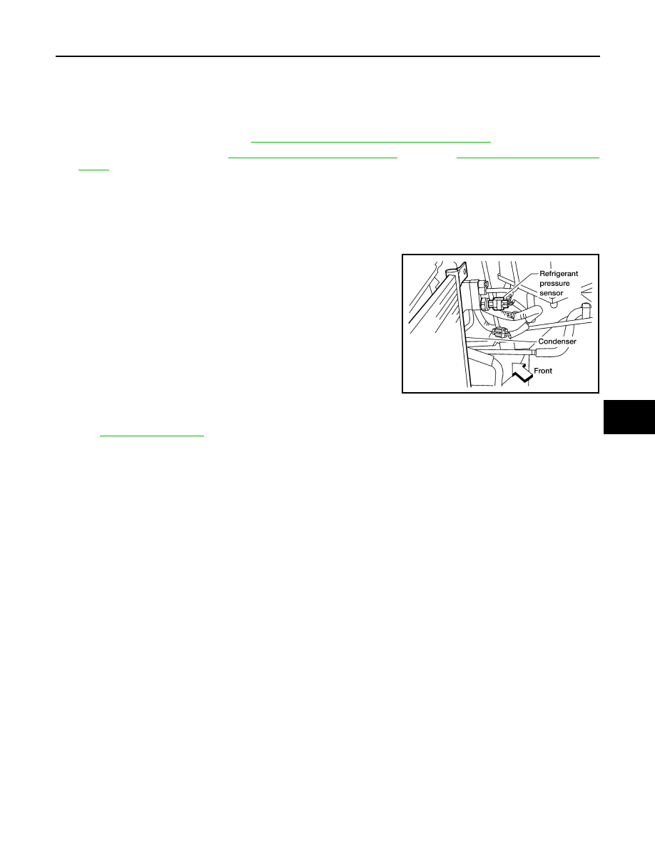
4. Disconnect the refrigerant pressure sensor harness connector.
5. Remove the refrigerant pressure sensor from the condenser.
6. Lift the condenser out of the mounting grommets and remove
the condenser.
NOTE:
The condenser and liquid tank are serviced as an assembly.
INSTALLATION
Installation is in the reverse order of removal.
CAUTION:
• Do not reuse O-rings.
• Apply A/C oil to the O-rings of the front high-pressure A/C pipe, refrigerant pressure sensor, and
front high-pressure flexible A/C hose for installation.
• After charging refrigerant, check for leaks.
• Replace the mounting grommets as necessary.
LJIA0177E
August 2012
2012 Pathfinder
HA-54
< REMOVAL AND INSTALLATION >
REFRIGERANT PRESSURE SENSOR
REFRIGERANT PRESSURE SENSOR
Removal and Installation for Refrigerant Pressure Sensor
INFOID:0000000007356328
REMOVAL
1. Discharge the refrigerant. Refer to
HA-36, "HFC-134a (R-134a) Service Procedure"
.
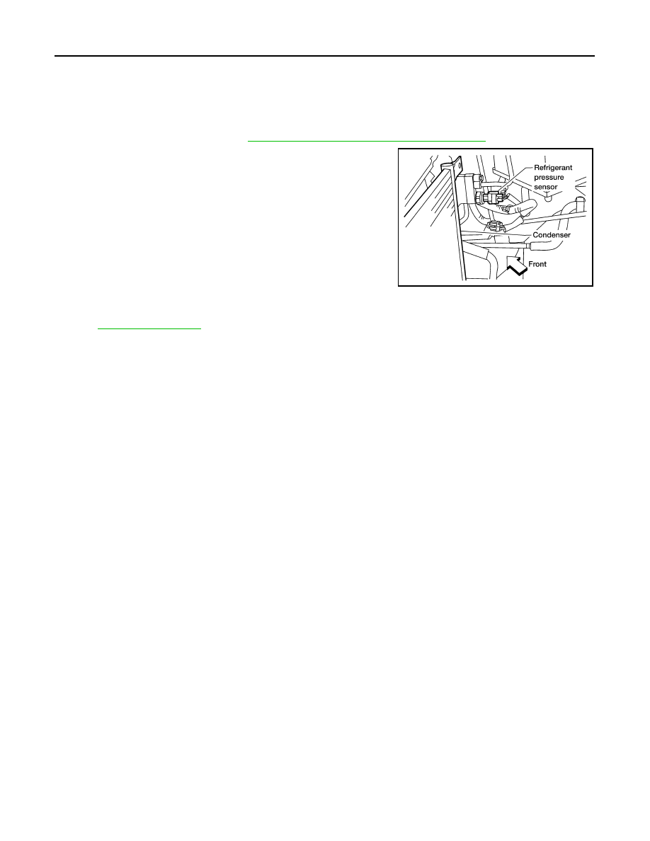
2. Disconnect the refrigerant pressure sensor harness connector
and remove the refrigerant pressure sensor from the condenser.
CAUTION:
Be careful not to damage the condenser fins.
INSTALLATION
Installation is in the reverse order of removal.
CAUTION:
• Be careful not to damage the condenser fins.
• Do not reuse O-rings.
• Apply A/C oil to the O-ring of the refrigerant pressure sensor for installation.
• After charging refrigerant, check for leaks.
LJIA0177E
August 2012
2012 Pathfinder
EXPANSION VALVE
HA-55
< REMOVAL AND INSTALLATION >
C
D
E
F
G
H
J
K
L
M
A
B
HA
N
O
P
EXPANSION VALVE
Removal and Installation - Expansion Valve
INFOID:0000000007356329
REMOVAL
1. Discharge the refrigerant. Refer to
HA-25, "HFC-134a (R-134a) Service Procedure"
.
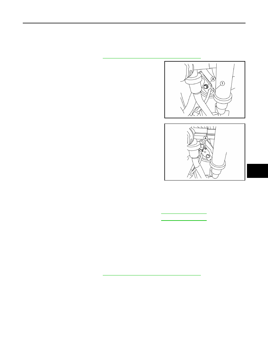
2. Remove the high-pressure pipe and low-pressure pipe bolt (A)
from the front expansion valve (1).
CAUTION:
Cap or wrap the A/C refrigerant pipe ends and the evapora-
tor pipe ends with a suitable material such as vinyl tape to
avoid the entry of air and contaminants.
3. Remove the front expansion valve bolts (A).
4. Remove the front expansion valve.
INSTALLATION
Installation is in the reverse order of removal.
CAUTION:
• Do not reuse O-rings.
• Apply A/C oil to the O-rings on the front expansion valve and the A/C refrigerant pipes for installa-
tion.
• After charging refrigerant, check for leaks.
Removal and Installation - Rear Expansion Valve
INFOID:0000000008807281
REMOVAL
1. Discharge the refrigerant. Refer to
HA-25, "HFC-134a (R-134a) Service Procedure"
.
2. Reposition the RH third row seatback out of the way of the access panel.
3. Open the access panel in the luggage side lower finisher RH.
4. Disconnect the rear high-pressure and low-pressure A/C pipes from the rear expansion valve.
CAUTION:
Cap or wrap the A/C refrigerant pipe ends with a suitable material such as vinyl tape to avoid the
entry of air and contaminants.
5. Remove the rear expansion valve.
INSTALLATION
Installation is in the reverse order of removal.
ALIIA0626ZZ
ALIIA0625ZZ
Expansion valve bolts
: Refer to
A/C refrigerant pipe to expansion valve bolt
: Refer to
August 2012
2012 Pathfinder
HA-56
< REMOVAL AND INSTALLATION >
EXPANSION VALVE
CAUTION:
• Do not reuse O-rings.
• Apply A/C oil to the O-rings on then front expansion valve and the A/C refrigerant pipes for installa-
tion.
• After charging refrigerant, check for leaks.
Rear expansion valve bolts
: Refer to
A/C refrigerant pipe to expansion valve bolt
: Refer to
August 2012
2012 Pathfinder
AMBIENT SENSOR
HA-57
< REMOVAL AND INSTALLATION >
C
D
E
F
G
H
J
K
L
M
A
B
HA
N
O
P
AMBIENT SENSOR
Removal and Installation
INFOID:0000000007356330
REMOVAL
1. Remove the front grille. Refer to
EXT-20, "Removal and Installation"
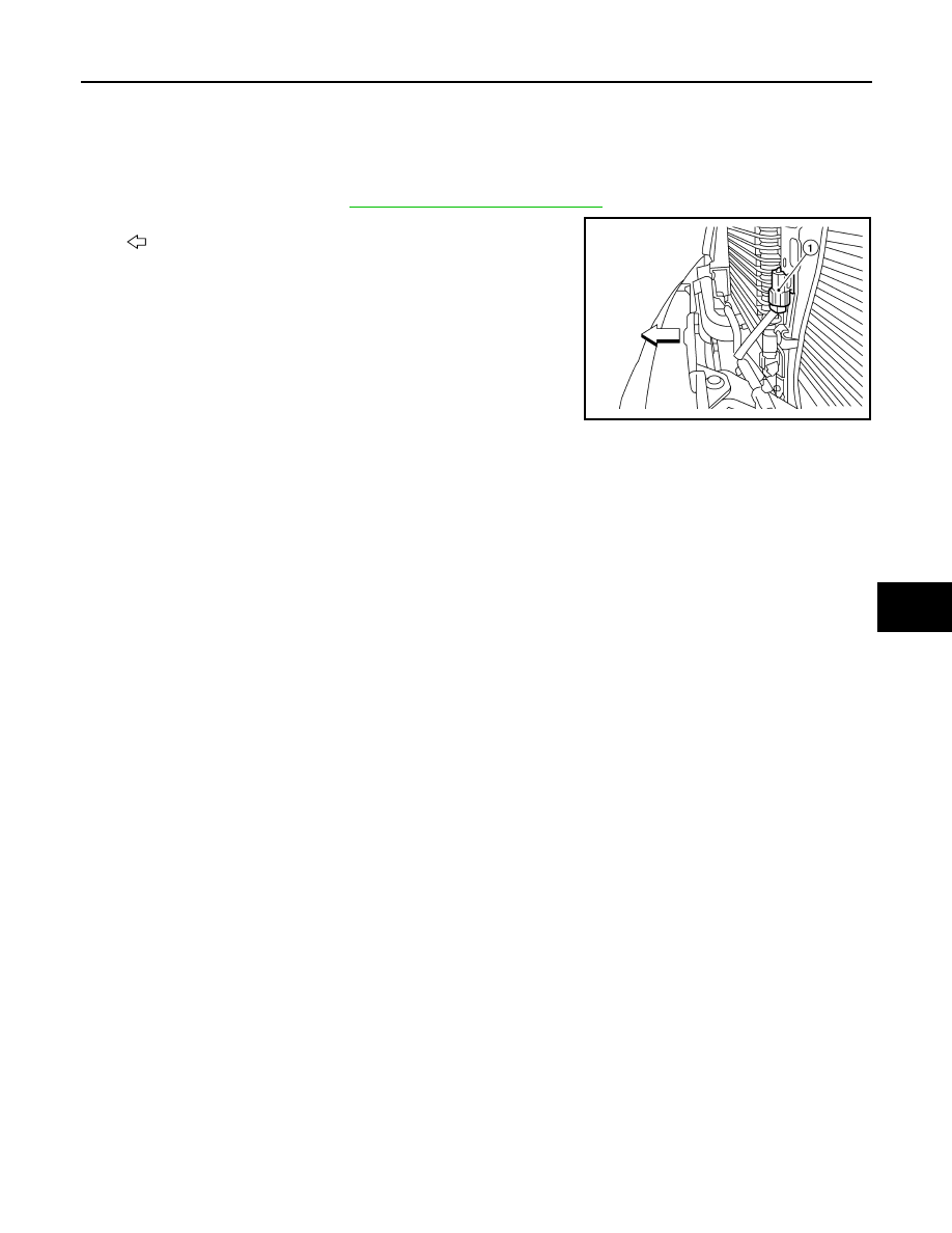
2. Disconnect the ambient sensor (1) electrical connector.
•
: Front
NOTE:
The ambient sensor is located behind the front grille, below the
hood latch.
3. Release the ambient sensor (1) clip and then remove the ambi-
ent sensor.
INSTALLATION
Installation is in the reverse order of removal.
AWIIA0262ZZ
August 2012
2012 Pathfinder
HA-58
< REMOVAL AND INSTALLATION >
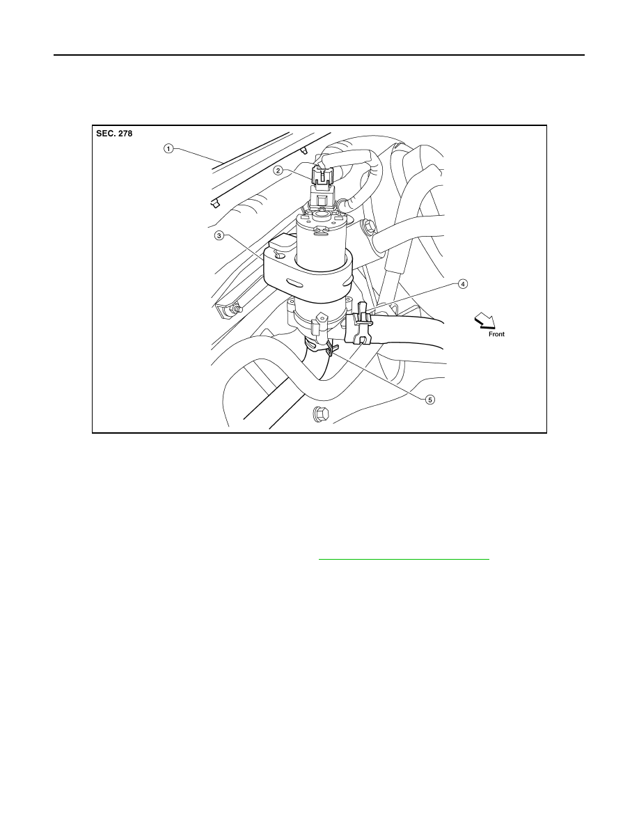
HEATER PUMP
HEATER PUMP
Removal and Installation
INFOID:0000000007356331
Heater Pump
NOTE:
• Only the VQ40DE engine is equipped with a heater pump for the rear heater system.
• When removing components such as hoses, tubes/lines, etc., cap or plug openings to prevent fluid from
spilling.
REMOVAL
1. Partially drain the engine cooling system. Refer to
CO-12, "Changing Engine Coolant"
2. Disconnect the heater pump electrical connector.
3. Disconnect the two heater hoses.
4. Remove the heater pump from the bracket securing the heater pump to the cowl top.
CAUTION:
Do not disassemble the heater pump, replace the heater pump as an assembly.
INSTALLATION
Installation is in the reverse order of removal.
CAUTION:
• The heater pump rubber mount must be fully seated on the bracket.
• Do not disassemble the heater pump, replace the heater pump as an assembly.
LBIA0414E
1.
Cowl top
2.
Heater pump electrical connector
3.
Heater pump
4.
Heater hose and clamp
5.
Heater hose and clamp
August 2012
2012 Pathfinder

SERVICE DATA AND SPECIFICATIONS (SDS)
HA-59
< SERVICE DATA AND SPECIFICATIONS (SDS)
C
D
E
F
G
H
J
K
L
M
A
B
HA
N
O
P
SERVICE DATA AND SPECIFICATIONS (SDS)
SERVICE DATA AND SPECIFICATIONS (SDS)
Service Data and Specification (SDS)
INFOID:0000000007356332
COMPRESSOR
OIL
REFRIGERANT
* : Always check with Parts Department for latest parts information.
Make
ZEXEL VALEO CLIMATE CONTROL*
Model
DKS-17D
Type
Swash plate
Displacement
175.5 cm
3
(10.7 in
3
) / revolution
Cylinder bore
×
stroke
30.5 mm (1.20 in) x 24.0 mm (0.94 in)
Direction of rotation
Clockwise (viewed from drive end)
Drive belt
Poly V
Name
NISSAN A/C System Oil Type S or equivalent
Capacity
With rear A/C
210 m (7.1 US fl oz, 7.4 Imp fl oz)
Without rear A/C
180 m (6.1 US fl oz, 6.3 Imp fl oz)
Type
HFC 134a (R-134a)
Capacity
With rear A/C
0.85
±
0.05 kg (1.87
±
0.11 lb)
Without rear A/C
0.70
±
0.05 kg (1.54
±
0.11 lb)
August 2012
2012 Pathfinder
HAC-1
VENTILATION, HEATER & AIR CONDITIONER
C
D
E
F
G
H
J
K
L
M
SECTION
HAC
A
B
HAC
N
O
P
CONTENTS
HEATER & AIR CONDITIONING CONTROL SYSTEM
AUTOMATIC AIR CONDITIONER
BASIC INSPECTION . . . . . . . . .
DIAGNOSIS AND REPAIR WORKFLOW . . ..
How to Perform Trouble Diagnosis For Quick And
Accurate Repair . . . . . . . . . . . . . ....
INSPECTION AND ADJUSTMENT . . . . . .
Operational Check (Front) . . . . . . . . . .....
Operational Check (Rear) . . . . . . . . . .....
SYSTEM DESCRIPTION . . . . . . . ..
FUNCTION INFORMATION . . . . . . . .
Component Part Location . . . . . . . . . .....
Symptom Table . . . . . . . . . . . . . ...
REFRIGERATION SYSTEM . . . . . . . ..
Refrigerant Cycle . . . . . . . . . . . . .
Refrigerant System Protection . . . . . . . .
AUTOMATIC AIR CONDITIONER SYSTEM . .
Control System Diagram . . . . . . . . . . .
Control System Description . . . . . . . . . .
Discharge Air Flow (Front) . . . . . . . . . ..
Switches And Their Control Function (Front) . . ..
Switches And Their Control Function (Rear) . . ...
DIAGNOSIS SYSTEM (HVAC) . . . . . . ..
CONSULT Function (HVAC) . . . . . . . . ...
DIAGNOSIS SYSTEM (BCM) . . . . . . .
COMMON ITEM . . . . . . . . . . . . . . .
COMMON ITEM : CONSULT Function (BCM -
COMMON ITEM) . . . . . . . . . . . . . .
AIR CONDITIONER . . . . . . . . . . . . ...
AIR CONDITIONER : CONSULT Function (BCM -
AIR CONDITIONER) . . . . . . . . . . . ...
SELF-DIAGNOSIS FUNCTION . . . . . . ..
A/C Auto Amp. Self-Diagnosis . . . . . . . . .
A/C and AV Switch Assembly Self-Diagnosis . . .
A/C System Self-Diagnosis Code Chart . . . . ..
DTC/CIRCUIT DIAGNOSIS . . . . . . .
MODE DOOR MOTOR . . . . . . . . . ..
System Description . . . . . . . . . . . . ..
Mode Door Motor (Front) Component Function
Check . . . . . . . . . . . . . . . . . ..
Mode Door Motor (Front) Diagnosis Procedure . ..
AIR MIX DOOR MOTOR . . . . . . . . ...
System Description . . . . . . . . . . . . ..
Air Mix Door Motor (Driver) Component Function
Check . . . . . . . . . . . . . . . . . ..
Air Mix Door Motor (Driver) Diagnosis Procedure .
Air Mix Door Motor (Passenger) Component
Function Check . . . . . . . . . . . . . .
Air Mix Door Motor (Passenger) Diagnosis Proce-
dure . . . . . . . . . . . . . . . . . . .
INTAKE DOOR MOTOR . . . . . . . . ...
System Description . . . . . . . . . . . . ..
Intake Door Motor Component Function Check . ..
Intake Door Motor Diagnosis Procedure . . . . .
BLOWER MOTOR CONTROL SYSTEM . . ..
System Description . . . . . . . . . . . . ..
Front Blower Motor Component Function Check .
Front Blower Motor Diagnosis Procedure . . . .
Front Blower Motor Component Inspection . . . .
Rear Blower Motor Description . . . . . . . .
Rear Blower Motor Component Function Check . .
Rear Air Control (Front) Diagnosis Procedure #1 .
Rear Air Control (Rear) Diagnosis Procedure #2 .
Rear Air Control (Rear) Diagnosis Procedure #3 .
Rear Air Control (Rear) Diagnosis Procedure #4 .
Rear Blower Motor And Relay Component Inspec-
tion . . . . . . . . . . . . . . . . . . ...
REAR AIR CONTROL SYSTEM . . . . . ...
August 2012
2012 Pathfinder
Нет комментариевНе стесняйтесь поделиться с нами вашим ценным мнением.
Текст