Nissan Pathfinder (2012 year). Instruction — part 417

HAC-58
< DTC/CIRCUIT DIAGNOSIS >
[AUTOMATIC AIR CONDITIONER]
REAR AIR CONTROL SYSTEM
4. Check for hot air at rear foot discharge air outlets in the maximum heat position and cold air at rear roof
discharge air outlets in the maximum cold position.
Does the rear air control (rear) operate properly?
YES
>> Inspection End.
NO
>> Check rear air control (rear). Refer to
HAC-62, "Rear Air Control (Rear) Diagnosis Procedure"
.
Rear Air Control (Front) Diagnosis Procedure
INFOID:0000000007356375
Regarding Wiring Diagram information, refer to
HAC-95, "Wiring Diagram - Automatic"
DIAGNOSTIC PROCEDURE FOR REAR AIR CONTROL (FRONT)
SYMPTOM:
• Temperature/mode operation is malfunctioning.
1.
CHECK REAR AIR CONTROL (FRONT) REAR CONTROL SELECT SWITCH
1. With the rear blower motor set to maximum speed, rotate the rear temperature/mode control dial back and
forth slowly between maximum heat and maximum cooling.
2. Check for the tone of the air blowing from the rear vents to change, and for the air to move between the
roof vents and the foot vents.
Is the inspection result normal?
YES
>> Rear air control and air mix door (rear) are working properly. Refer to
for insufficient cooling or
HAC-120, "Component Function Check"
for insufficient
heating.
NO
>> GO TO 2.
2.
CHECK AIR MIX DOOR MOTOR (REAR) POSITION BALANCED RESISTOR (PBR) FEEDBACK VOLT-
AGE
1. Using CONSULT, check "RR FDBCK" in "DATA MONITOR" mode in "HVAC". Refer to
.
2. Observe "RR FDBCK" voltage while rotating rear temperature control dial (front) between 32
°
C (90
°
F)
and 18
°
C (60
°
F).
Is the inspection result normal?
YES
>> • Air mix door motor (rear) is OK.
• Inspect air mix door (rear) for mechanical failure and repair if necessary.
NO
>> GO TO 3.
3.
CHECK REAR AIR CONTROL (FRONT) POWER SUPPLY
1. Turn ignition switch ON.
2. Check voltage between rear air control (front) harness connector R2 terminal 10 and ground.
Is the inspection result normal?
YES
>> GO TO 4.
NO
>> Repair harness or connector.
4.
CHECK REAR AIR CONTROL (FRONT) GROUND CIRCUIT
1. Turn ignition switch OFF.
2. Check continuity between rear air control (front) harness connector R2 terminal 1 and ground.
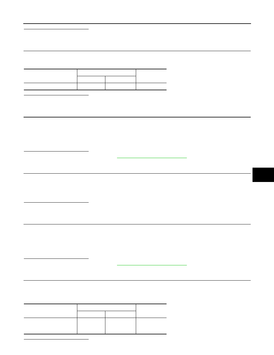
Monitor Item
Condition
Results
RR FDBCK
Rotate rear temperature control dial (front) be-
tween maximum cold and maximum hot
Voltage varies between 0.2 and 4.8V.
Battery voltage should exist.
Continuity should exist.
August 2012
2012 Pathfinder
REAR AIR CONTROL SYSTEM
HAC-59
< DTC/CIRCUIT DIAGNOSIS >
[AUTOMATIC AIR CONDITIONER]
C
D
E
F
G
H
J
K
L
M
A
B
HAC
N
O
P
Is the inspection result normal?
YES
>> GO TO 5.
NO
>> Repair harness or connector.
5.
CHECK REAR AIR CONTROL (FRONT) REFERENCE VOLTAGE
1. Turn ignition switch ON.
2. Check voltage between rear air control (front) harness connector R2 terminal 3 and ground.
Is the inspection result normal?
YES
>> GO TO 7.
NO
>> GO TO 6.
6.
CHECK REAR AIR CONTROL (FRONT) REFERENCE VOLTAGE CIRCUIT
1. Disconnect A/C auto amp. and rear air control (front) connectors.
2. Check continuity between A/C auto amp. harness connector M50 terminal 28 and rear air control (front)
harness connector R2 terminal 3.
Is the inspection result normal?
YES
>> Replace A/C auto amp. Refer to
VTL-7, "Removal and Installation"
.
NO
>> Repair harness or connector.
7.
CHECK REAR AIR CONTROL (FRONT) REFERENCE GROUND CIRCUIT
1. Turn ignition switch OFF.
2. Check continuity between rear air control (front) harness connector R2 terminal 8 and ground.
Is the inspection result normal?
YES
>> GO TO 9.
NO
>> GO TO 8.
8.
CHECK REAR AIR CONTROL (FRONT) REFERENCE GROUND CIRCUIT FOR OPEN
1. Disconnect A/C auto amp. connector and rear air control (front) harness connector.
2. Check continuity between A/C auto amp. harness connector M49 terminal 3 and rear air control (front)
harness connector R2 terminal 8.
Is the inspection result normal?
YES
>> Replace A/C auto amp. Refer to
VTL-7, "Removal and Installation"
.
NO
>> Repair harness or connector.
9.
CHECK REAR AIR CONTROL (FRONT) AUX TEMP POT VOLTAGE
1. Turn ignition switch ON.
2. Check voltage between A/C auto amp. harness connector M50 terminal 37 and ground while turning knob
between full cold and full hot.
Is the inspection result normal?
Connector
Terminals
Voltage (Ap-
prox.)
(+)
(-)
Rear air control (front): R2
3
Ground
4.5V
Continuity should exist.
Continuity should exist.
Continuity should exist.
Connector
Terminals
Voltage (Ap-
prox.)
(+)
(-)
A/C auto amp.: M50
37
Ground
Varying be-
tween 0.1V and
4.9V
August 2012
2012 Pathfinder
HAC-60
< DTC/CIRCUIT DIAGNOSIS >
[AUTOMATIC AIR CONDITIONER]
REAR AIR CONTROL SYSTEM
YES
>> GO TO 11.
NO
>> GO TO 10.
10.
CHECK REAR AIR CONTROL (FRONT) AUX TEMP POT CIRCUIT
1. Turn ignition switch OFF.
2. Disconnect A/C auto amp. connector and rear air control (front) connector.
3. Check continuity between A/C auto amp. harness connector M50 terminal 37 and rear air control (front)
harness connector R2 terminal 7.
Is the inspection result normal?
YES
>> Replace A/C auto amp. Refer to
VTL-7, "Removal and Installation"
NO
>> Repair harness or connector.
11.
CHECK AIR MIX DOOR MOTOR (REAR) CIRCUITS FOR OPEN AND SHORT TO GROUND
1. Turn ignition switch OFF.
2. Disconnect the A/C auto amp. harness connector M50 and the air mix door motor (rear) harness connec-
tor B155.
3. Check continuity between A/C auto amp. harness connector M50 terminals 43, 44 and the air mix door
motor (rear) harness connector B155 terminal 1, 6.
4. Check continuity between A/C auto amp. harness connector M50 terminals 43, 44 and ground.
Is the inspection result normal?
YES
>> GO TO 12.
NO
>> Repair or replace harness as necessary.
12.
CHECK A/C AUTO AMP. FOR AIR MIX DOOR MOTOR (REAR) POWER AND GROUND
1. Reconnect A/C auto amp. harness connector.
2. Turn ignition switch ON.
3. Rotate temperature control dial (rear) to maximum hot.
4. Check voltage between A/C auto amp. harness connector M50 terminal 43 and terminal 44 while rotating
temperature control dial (rear) to maximum cold and back to maximum heat.
Is the inspection result normal?
YES
>> GO TO 13.
NO
>> Replace A/C auto amp. Refer to
VTL-7, "Removal and Installation"
13.
CHECK AIR MIX DOOR MOTOR (REAR) PBR CIRCUITS FOR OPEN AND SHORT TO GROUND
1. Turn ignition switch OFF.
2. Disconnect the A/C auto amp. harness connectors M49 and M50.
3. Check continuity between A/C auto amp. harness connector M49 terminal 3 and M50 terminal 28 and air
mix door motor (rear) harness connector B155 terminal 2, 3.
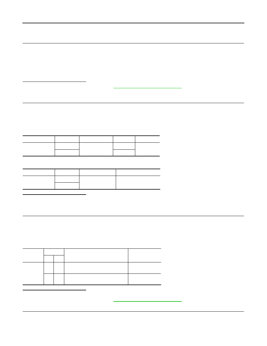
Continuity should exist.
Connector
Terminal
Connector
Terminal
Continuity
M50
43
B155
1
Yes
44
6
Connector
Terminal
—
Continuity
M50
43
Ground
No
44
Connector
Terminals
Condition Voltage
(Approx.)
(+) (-)
M50
43
44
Rotate rear temperature control dial
(front) to maximum cold
Battery voltage
44
43
Rotate rear temperature control dial
(front) to maximum heat
Battery voltage
August 2012
2012 Pathfinder
REAR AIR CONTROL SYSTEM
HAC-61
< DTC/CIRCUIT DIAGNOSIS >
[AUTOMATIC AIR CONDITIONER]
C
D
E
F
G
H
J
K
L
M
A
B
HAC
N
O
P
4. Check continuity between A/C auto amp. harness connector M49 terminal 3, M50 terminal 28 and ground.
Is the inspection result normal?
YES
>> GO TO 14.
NO
>> Repair or replace harness as necessary.
14.
CHECK PBR FEEDBACK SIGNAL CIRCUIT FOR OPEN AND SHORT TO GROUND
1. Check continuity between A/C auto amp. harness connector M50 terminal 30 and air mix door motor
(rear) harness connector B155 terminal 4.
2. Check continuity between A/C auto amp. harness connector M50 terminal 30 and ground.
Is the inspection result normal?
YES
>> GO TO 15.
NO
>> Repair or replace harness as necessary.
15.
CHECK A/C AUTO AMP. FOR 5 VOLT REFERENCE (VREF), VREF RETURN, AND FEEDBACK SIG-
NAL
1. Reconnect A/C auto amp. harness connectors.
2. Turn ignition switch ON.
3. Check voltage between A/C auto amp. harness connector M49 terminal 3, and M50 terminal 28.
4. Check voltage between A/C auto amp. harness connector M50 terminal 30 and ground.
Is the inspection result normal?
YES
>> GO TO 16.
NO
>> Replace A/C auto amp. Refer to
VTL-7, "Removal and Installation"
.
16.
CHECK A/C AUTO AMP. FOR FEEDBACK SIGNAL
1. Reconnect the air mix door motor (rear) harness connector B155.
2. Check voltage between A/C auto amp. harness connector M50 terminal 30 and ground.
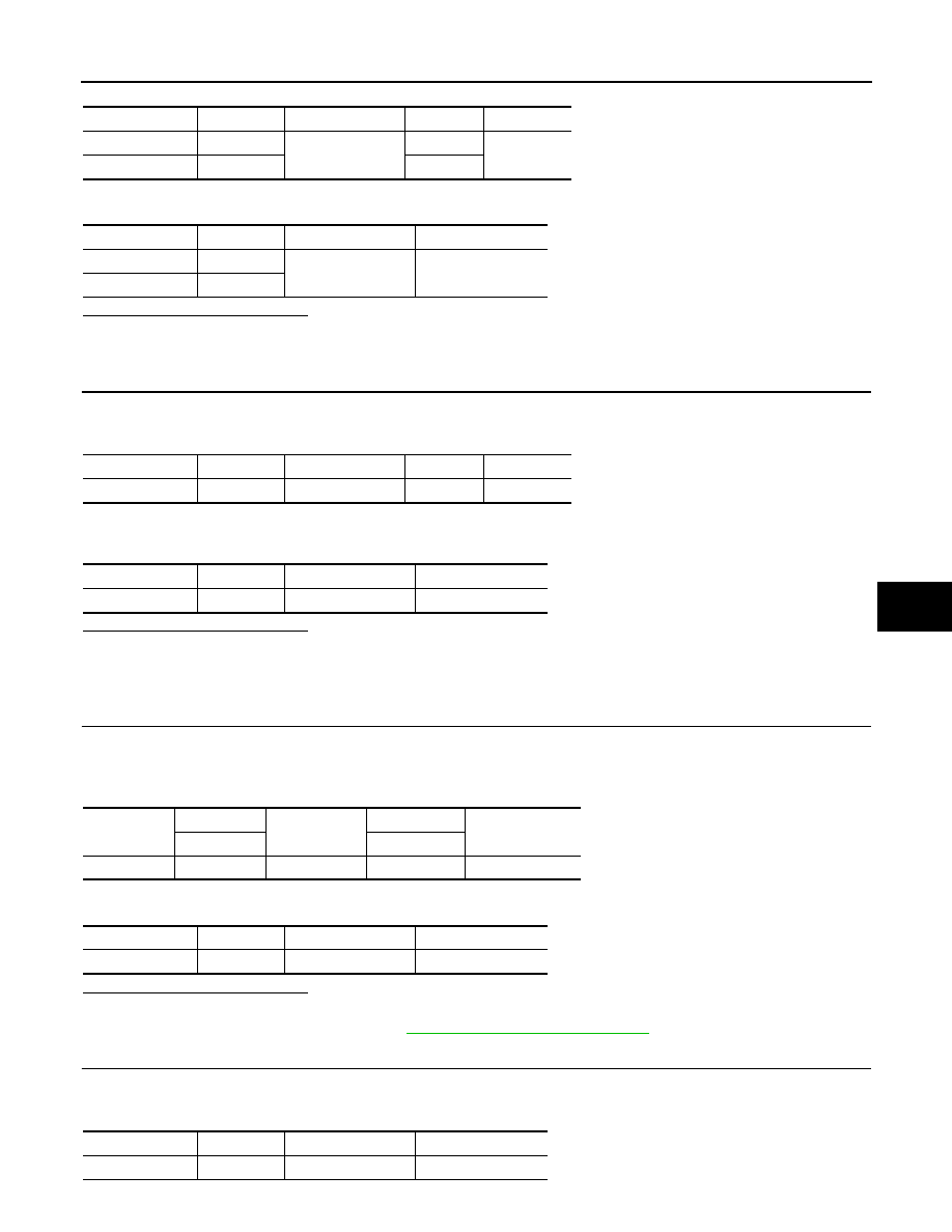
Connector
Terminal
Connector
Terminal
Continuity
M49
3
B155
2
Yes
M50
28
3
Connector
Terminal
—
Continuity
M49
3
Ground
No
M50
28
Connector
Terminal
Connector
Terminal
Continuity
M50
30
B155
4
Yes
Connector
Terminal
—
Continuity
M50
30
Ground
No
Connector
Terminals
Connector
Terminals
Voltage (Approx.)
(+)
(-)
M50
28
M49
3
5V
Connector
Terminal
—
Voltage (Approx.)
M50
30
Ground
0V
Connector
Terminal
—
Voltage (Approx.)
M50
30
Ground
0.1 to 4.9V
August 2012
2012 Pathfinder

HAC-62
< DTC/CIRCUIT DIAGNOSIS >
[AUTOMATIC AIR CONDITIONER]
REAR AIR CONTROL SYSTEM
Is the inspection result normal?
YES
>> Inspect air mix door (rear) for binding or mechanical failure. If air mix door (rear) moves freely,
replace A/C auto amp. Refer to
VTL-7, "Removal and Installation"
.
NO
>> Replace the air mix door motor (rear). Refer to
VTL-30, "Removal and Installation"
Rear Air Control (Rear) Diagnosis Procedure
INFOID:0000000007356376
Regarding Wiring Diagram information, refer to
HAC-95, "Wiring Diagram - Automatic"
1.
CHECK REAR AIR CONTROL (FRONT) REAR CONTROL SELECT SWITCH
Did the REAR CTRL lamp illuminate when selected?
Is the inspection result normal?
YES
>> GO TO 2.
NO
>> GO TO 3.
2.
CHECK AIR MIX DOOR MOTOR (REAR) POSITION BALANCED RESISTOR (PBR) FEEDBACK VOLT-
AGE
1. Turn ignition switch ON.
2. Using CONSULT, check "RR FDBCK" in "DATA MONITOR" mode in "HVAC". Refer to
.
3. Observe "RR FDBCK" voltage while rotating rear temperature control dial (rear) between 32
°
C (90
°
F) and
18
°
C (60
°
F).
Is the inspection result normal?
YES
>> • Air mix door motor (rear) is OK.
• Inspect air mix door (rear) for mechanical failure and repair if necessary.
NO
>> GO TO 12.
3.
CHECK REAR AIR CONTROL (REAR) GROUND CIRCUIT
1. Turn ignition switch OFF.
2. Check continuity between rear air control (rear) harness connector M208 terminal 1 and ground.
Is the inspection result normal?
YES
>> GO TO 4.
NO
>> Repair harness or connector.
4.
CHECK REAR AIR CONTROL (FRONT) REAR CONTROL TELLTALE SIGNAL
While repeatedly pressing and releasing the rear air control (front) rear control select switch, check voltage
between rear air control (front) harness connector R2 terminal 4 and ground.
Is the inspection result normal?
YES
>> Replace rear air control (front). Refer to
VTL-7, "Removal and Installation"
NO
>> GO TO 5.
Monitor Item
Condition
Results
RR FDBCK
Rotate rear temperature control dial (rear) be-
tween maximum cold and maximum hot
Voltage varies between 0.1 and 4.9V.
Continuity should exist.
Connector
Terminals
Voltage (Ap-
prox.)
(+)
(-)
Rear air control (front): R2
4
Ground
Switching be-
tween battery
voltage and
7.5V
August 2012
2012 Pathfinder

REAR AIR CONTROL SYSTEM
HAC-63
< DTC/CIRCUIT DIAGNOSIS >
[AUTOMATIC AIR CONDITIONER]
C
D
E
F
G
H
J
K
L
M
A
B
HAC
N
O
P
5.
CHECK REAR AIR CONTROL (FRONT) REAR CONTROL SELECT SWITCH SIGNAL
While pressing and holding the rear air control (front) rear control select switch, check voltage between rear air
control (front) harness connector R2 terminal 5 and ground.
Is the inspection result normal?
YES
>> GO TO 8.
NO
>> GO TO 6.
6.
CHECK REAR AIR CONTROL (FRONT) REAR CONTROL SELECT SWITCH SIGNAL
1. Turn ignition switch OFF.
2. Disconnect A/C auto amp connector (M50).
3. Turn ignition switch ON.
4. While pressing and holding the rear air control (front) rear control select switch, check voltage between
rear air control (front) harness connector R2 terminal 5 and ground.
Is the inspection result normal?
YES
>> Replace A/C auto amp. Refer to
VTL-7, "Removal and Installation"
.
NO
>> GO TO 7.
7.
CHECK REAR AIR CONTROL (FRONT) REAR CONTROL SELECT SWITCH CIRCUIT
1. Turn ignition switch OFF.
2. Disconnect rear air control (front) connector.
3. Check continuity between A/C auto amp. harness connector M50 terminal 39 and rear air control (front)
harness connector R2 terminal 5.
4. Check continuity between A/C auto amp. harness connector M50 terminal 39 ground.
Is the inspection result normal?
YES
>> Replace rear air control (front). Refer to
VTL-7, "Removal and Installation"
NO
>> Repair harness or connector.
8.
CHECK REAR AIR CONTROL (FRONT) REAR CONTROL SELECT SWITCH SIGNAL
While pressing and holding the rear air control (front) rear control select switch, check voltage between A/C
auto amp. harness connector M50 terminal 39 and ground.
Is the inspection result normal?
YES
>> GO TO 9.
NO
>> Repair harness or connector.
9.
CHECK REAR AIR CONTROL (FRONT) REAR CONTROL TELLTALE SIGNAL
Repeatedly press and release the rear air control (front) rear control select switch and check voltage between
A/C auto amp. harness connector M50 terminal 35 and ground.
Connector
Terminals
Voltage (Ap-
prox.)
(+)
(-)
Rear air control (front): R2
5
Ground
6.5V
Connector
Terminals
Voltage (Ap-
prox.)
(+)
(-)
Rear air control (front): R2
5
Ground
6.5V
Continuity should exist.
Continuity should not exist.
Connector
Terminals
Voltage (Ap-
prox.)
(+)
(-)
A/C auto amp.: M50
39
Ground
6.5V
August 2012
2012 Pathfinder

HAC-64
< DTC/CIRCUIT DIAGNOSIS >
[AUTOMATIC AIR CONDITIONER]
REAR AIR CONTROL SYSTEM
Is the inspection result normal?
YES
>> Repair harness or connector.
NO
>> GO TO 10.
10.
CHECK REAR AIR CONTROL (FRONT) REAR CONTROL TELLTALE CIRCUIT
1. Turn ignition switch OFF.
2. Disconnect A/C auto amp connector M50 and rear air control (front) connector R2.
3. Check continuity between A/C auto amp. harness connector M50 terminal 35 and rear air control (front)
harness connector R2 terminal 4.
4. Check continuity between A/C auto amp. harness connector M50 terminal 35 and ground.
Is the inspection result normal?
YES
>> GO TO 11.
NO
>> Repair harness or connector.
11.
CHECK REAR AIR CONTROL (FRONT) REAR CONTROL TELLTALE CIRCUIT
1. Reconnect rear air control (front) connector.
2. Check continuity between rear air control (front) connector R2 terminal 4 and ground.
Is the inspection result normal?
YES
>> Replace A/C auto amp. Refer to
VTL-7, "Removal and Installation"
NO
>> Replace rear air control (front). Refer to
VTL-7, "Removal and Installation"
12.
CHECK REAR AIR CONTROL (REAR) GROUND CIRCUIT
1. Turn ignition switch OFF.
2. Check continuity between rear air control (rear) harness connector M208 terminal 1 and ground.
Is the inspection result normal?
YES
>> GO TO 13.
NO
>> Repair harness or connector.
13.
CHECK REAR AIR CONTROL (REAR) REFERENCE VOLTAGE
1. Turn ignition switch ON.
2. Check voltage between rear air control (rear) harness connector M208 terminal 3 and ground.
Is the inspection result normal?
YES
>> GO TO 15.
NO
>> GO TO 14.
14.
CHECK REAR AIR CONTROL (REAR) REFERENCE VOLTAGE CIRCUIT
Connector
Terminals
Voltage (Ap-
prox.)
(+)
(-)
A/C auto amp.: M50
35
Ground
Switching be-
tween battery
voltage and
7.5V
Continuity should exist.
Continuity should not exist.
Continuity should not exist.
Continuity should exist.
Connector
Terminals
Voltage (Ap-
prox.)
(+)
(-)
Rear air control (rear): M208
3
Ground
4.5V
August 2012
2012 Pathfinder

REAR AIR CONTROL SYSTEM
HAC-65
< DTC/CIRCUIT DIAGNOSIS >
[AUTOMATIC AIR CONDITIONER]
C
D
E
F
G
H
J
K
L
M
A
B
HAC
N
O
P
1. Disconnect A/C auto amp. connector.
2. Check continuity between A/C auto amp. harness connector M50 terminal 28 and rear air control (rear)
harness connector M208 terminal 3.
Is the inspection result normal?
YES
>> Replace A/C auto amp. Refer to
VTL-7, "Removal and Installation"
.
NO
>> Repair harness or connector.
15.
CHECK REAR AIR CONTROL (REAR) REFERENCE GROUND CIRCUIT
1. Turn ignition switch OFF.
2. Check continuity between rear air control (rear) harness connector M208 terminal 8 and ground.
Is the inspection result normal?
YES
>> GO TO 17
NO
>> GO TO 18.
16.
CHECK REAR AIR CONTROL (REAR) REFERENCE GROUND CIRCUIT FOR OPEN
1. Disconnect A/C auto amp. connector and rear air control (rear) harness connector.
2. Check continuity between A/C auto amp. harness connector M49 terminal 3 and rear air control (rear) har-
ness connector M208 terminal 8.
Is the inspection result normal?
YES
>> Replace A/C auto amp. Refer to
VTL-7, "Removal and Installation"
.
NO
>> Repair harness or connector.
17.
CHECK REAR AIR CONTROL (REAR) AUX TEMP POT VOLTAGE
1. Turn ignition ON.
2. Check voltage between rear air control (rear) harness connector M208 terminal 7 and ground while turn-
ing knob between full cold and full hot.
Is the inspection result normal?
YES
>> GO TO 19.
NO
>> GO TO 18.
18.
CHECK REAR AIR CONTROL (REAR) AUX TEMP POT CIRCUIT
1. Turn ignition switch OFF.
2. Disconnect A/C auto amp. connector and rear air control (rear) connector.
3. Check continuity between A/C auto amp. harness connector M50 terminal 51 and rear air control (rear)
harness connector M208 terminal 7.
4. Check continuity between A/C auto amp. harness connector M50 terminal 51 and ground.
Is the inspection result normal?
YES
>> Replace rear air control (rear) switch. Refer to
VTL-7, "Removal and Installation"
.
NO
>> Repair harness or connector.
Continuity should exist.
Continuity should exist.
Continuity should exist.
Connector
Terminals
Voltage (Ap-
prox.)
(+)
(-)
Rear air control (rear): M208
7
Ground
Varying be-
tween 0.1V and
4.9V
Continuity should exist.
Continuity should not exist.
August 2012
2012 Pathfinder
Нет комментариевНе стесняйтесь поделиться с нами вашим ценным мнением.
Текст