Nissan Pathfinder (2012 year). Instruction — part 327

P0137, P0157 HO2S2
EC-697
< DTC/CIRCUIT DIAGNOSIS >
[VK56DE]
C
D
E
F
G
H
I
J
K
L
M
A
EC
N
P
O
1. Check harness continuity between ECM terminal and HO2S2 terminal as per the following.
Refer to Wiring Diagram.
2. Check harness continuity between the following terminals and ground.
Refer to Wiring Diagram.
3. Also check harness for short to power.
OK or NG
OK
>> GO TO 5.
NG
>> Repair open circuit or short to ground or short to power in harness or connectors.
5.
CHECK HEATED OXYGEN SENSOR 2
EC-697, "Component Inspection"
OK or NG
OK
>> GO TO 6.
NG
>> Replace malfunctioning heated oxygen sensor 2. Refer to
.
6.
CHECK INTERMITTENT INCIDENT
GI-37, "Intermittent Incident"
.
>>
INSPECTION END
Component Inspection
INFOID:0000000007358568
HEATED OXYGEN SENSOR 2
With CONSULT
1. Turn ignition switch ON and select “DATA MONITOR” mode with CONSULT.
2. Start engine and warm it up to the normal operating temperature.
3. Turn ignition switch OFF and wait at least 10 seconds.
4. Start engine and keep the engine speed between 3,500 and 4,000 rpm for at least 1 minute under no load.
5. Let engine idle for 1 minute.
6. Select “FUEL INJECTION” in “ACTIVE TEST” mode, and select “HO2S2 (B1)/(B2)” as the monitor item
with CONSULT.
DTC
Terminals
Bank
ECM
Sensor
P0137
55
1
1
P0157
74
1
2
Continuity should exist.
DTC
Terminals
Bank
ECM
Sensor
P0137
55
1
1
P0157
74
1
2
Continuity should not exist.
August 2012
2012 Pathfinder
EC-698
< DTC/CIRCUIT DIAGNOSIS >
[VK56DE]
P0137, P0157 HO2S2
7. Check “HO2S2 (B1)/(B2)” at idle speed when adjusting “FUEL INJECTION” to
±
25%.
“HO2S2 (B1)/(B2)” should be above 0.58 V at least once when the “FUEL INJECTION” is + 25%.
“HO2S2 (B1)/(B2)” should be below 0.18 V at least once when the “FUEL INJECTION” is
−
25%.
CAUTION:
• Discard any heated oxygen sensor which has been dropped from a height of more than 0.5 m (19.7
in) onto a hard surface such as a concrete floor; use a new one.
• Before installing new heated oxygen sensor, clean exhaust system threads using Oxygen Sensor
Thread Cleaner [Commercial service tool (J-43897-18 or J-43897-12)] and approved Anti-seize Lubri-
cant (Commercial service tool).
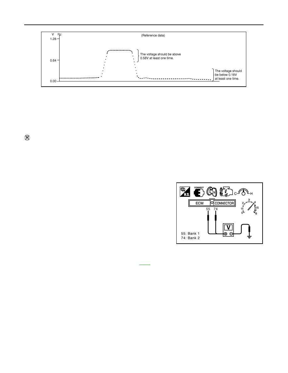
Without CONSULT
1. Start engine and warm it up to the normal operating temperature.
2. Turn ignition switch OFF and wait at least 10 seconds.
3. Start engine and keep the engine speed between 3,500 and 4,000 rpm for at least 1 minute under no load.
4. Let engine idle for 1 minute.
5. Set voltmeter probes between ECM terminal 55 [HO2S2 (B1) signal] and ground, or 74 [HO2S2 (B2) sig-
nal] and ground.
6. Check the voltage when revving up to 4,000 rpm under no load
at least 10 times.
(Depress and release accelerator pedal as soon as possible.)
The voltage should be above 0.58 V at least once during
this procedure.
The voltage should be below 0.18 V at least once during this
procedure.
If the voltage can be confirmed at step 6, step 7 is not nec-
essary.
7. Keep vehicle at idling for 10 minutes, then check voltage. Or
check the voltage when coasting from 80 km/h (50 MPH) in the
D position.
The voltage should be above 0.58 V at least once during this procedure.
The voltage should be below 0.18 V at least once during this procedure.
8. If NG, replace heated oxygen sensor 2. Refer to
CAUTION:
• Discard any heated oxygen sensor which has been dropped from a height of more than 0.5 m (19.7
in) onto a hard surface such as a concrete floor; use a new one.
• Before installing new heated oxygen sensor, clean exhaust system threads using Oxygen Sensor
Thread Cleaner [Commercial service tool (J-43897-18 or J-43897-12)] and approved Anti-seize Lubri-
cant (Commercial service tool).
JMBIA0605GB
PBIB2054E
August 2012
2012 Pathfinder
P0138, P0158 HO2S2
EC-699
< DTC/CIRCUIT DIAGNOSIS >
[VK56DE]
C
D
E
F
G
H
I
J
K
L
M
A
EC
N
P
O
P0138, P0158 HO2S2
Component Description
INFOID:0000000007358569
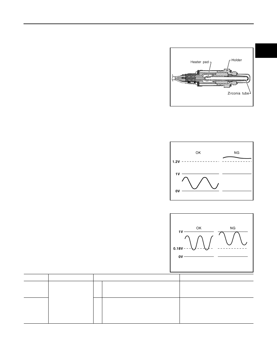
The heated oxygen sensor 2, after three way catalyst (manifold),
monitors the oxygen level in the exhaust gas on each bank.
Even if switching characteristics of the air fuel ratio (A/F) sensor 1
are shifted, the air-fuel ratio is controlled to stoichiometric, by the sig-
nal from the heated oxygen sensor 2.
This sensor is made of ceramic zirconia. The zirconia generates volt-
age from approximately 1 V in richer conditions to 0 V in leaner con-
ditions.
Under normal conditions the heated oxygen sensor 2 is not used for
engine control operation.
On Board Diagnosis Logic
INFOID:0000000007358570
The heated oxygen sensor 2 has a much longer switching time between rich and lean than the air fuel ratio (A/
F) sensor 1. The oxygen storage capacity of the three way catalyst (manifold) causes the longer switching
time.
MALFUNCTION A
To judge malfunctions of heated oxygen sensor 2, ECM monitors
whether the voltage is unusually high during various driving condi-
tions such as fuel cut.
MALFUNCTION B
To judge malfunctions of heated oxygen sensor 2, ECM monitors
whether the minimum voltage of sensor is sufficiently low during var-
ious driving conditions such as fuel cut.
DTC Confirmation Procedure
INFOID:0000000007358571
Perform PROCEDURE FOR MALFUNCTION A first.
SEF327R
PBIB1848E
PBIB2376E
DTC No.
Trouble diagnosis name
DTC detecting condition
Possible cause
P0138
0138
(Bank 1)
Heated oxygen sensor 2
circuit high voltage
A)
An excessively high voltage from the sensor
is sent to ECM.
• Harness or connectors
(The sensor circuit is open or shorted)
• Heated oxygen sensor 2
P0158
0158
(Bank 2)
B)
The minimum voltage from the sensor is not
reached to the specified voltage.
• Harness or connectors
(The sensor circuit is open or shorted)
• Heated oxygen sensor 2
• Fuel pressure
• Fuel injector
August 2012
2012 Pathfinder

EC-700
< DTC/CIRCUIT DIAGNOSIS >
[VK56DE]
P0138, P0158 HO2S2
If 1st trip DTC cannot be confirmed, perform PROCEDURE FOR MALFUNCTION B.
NOTE:
If DTC Confirmation Procedure has been previously conducted, always perform the following before conduct-
ing the next step.
1. Turn ignition switch OFF and wait at least 10 seconds.
2. Turn ignition switch ON.
3. Turn ignition switch OFF and wait at least 10 seconds.
PROCEDURE FOR MALFUNCTION A
With CONSULT
1. Turn ignition switch ON and select “DATA MONITOR” mode with CONSULT.
2. Start engine and warm it up to the normal operating temperature.
3. Turn ignition switch OFF and wait at least 10 seconds.
4. Turn ignition switch ON.
5. Turn ignition switch OFF and wait at least 10 seconds.
6. Start engine and keep the engine speed between 3,500 and 4,000 rpm for at least 1 minute under no load.
7. Let engine idle for 2 minutes.
8. Check 1st trip DTC.
9. If 1st trip DTC is detected, go to
With GST
Follow the procedure “With CONSULT” above.
PROCEDURE FOR MALFUNCTION B
With CONSULT
TESTING CONDITION:
For better results, perform “DTC WORK SUPPORT” at a temperature of 0 to 30
°
C (32 to 86
°
F).
1. Turn ignition switch ON and select “DATA MONITOR” mode with CONSULT.
2. Start engine and warm it up to the normal operating temperature.
3. Turn ignition switch OFF and wait at least 10 seconds.
4. Turn ignition switch ON.
5. Turn ignition switch OFF and wait at least 10 seconds.
6. Start engine and keep the engine speed between 3,500 and 4,000 rpm for at least 1 minute under no load.
7. Let engine idle for 1 minute.
8. Check that “COOLAN TEMP/S” indicates more than 70
°
C (158
°
F).
If not, warm up engine and go to next step when “COOLAN TEMP/S” indication reaches 70
°
C (158
°
F).
9. Open engine hood.
10. Select “HO2S2 (B1) P1146” (for DTC P0138) or “HO2S2 (B2) P1166” (for DTC P0158) of “HO2S2” in
“DTC WORK SUPPORT” mode with CONSULT.
11. Follow the instructions displayed.
NOTE:
It will take at most 10 minutes until “COMPLETED” is displayed.
12. Check that “OK” is displayed after touching “SELF-DIAG RESULTS”.
If “NG” is displayed, go to
.
If “CAN NOT BE DIAGNOSED” is displayed, perform the following procedure.
a. Turn ignition switch OFF and leave the vehicle in a cool place (soak the vehicle).
b. Return to step 1.
Overall Function Check
INFOID:0000000007358572
PROCEDURE FOR MALFUNCTION B
Use this procedure to check the overall function of the heated oxygen sensor 2 circuit. During this check, a 1st
trip DTC might not be confirmed.
With GST
August 2012
2012 Pathfinder
P0138, P0158 HO2S2
EC-701
< DTC/CIRCUIT DIAGNOSIS >
[VK56DE]
C
D
E
F
G
H
I
J
K
L
M
A
EC
N
P
O
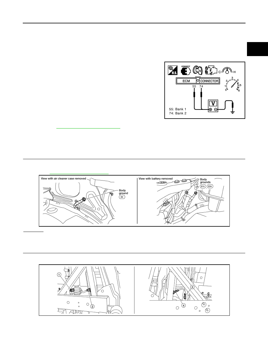
1. Start engine and warm it up to the normal operating temperature.
2. Turn ignition switch OFF and wait at least 10 seconds.
3. Start engine and keep the engine speed between 3,500 and 4,000 rpm for at least 1 minute under no load.
4. Let engine idle for 1 minute.
5. Set voltmeter probes between ECM terminal 55 [HO2S2 (B2) signal] and ground, or 74 [HO2S2 (B1) sig-
nal] and ground.
6. Check the voltage when revving up to 4,000 rpm under no load
at least 10 times.
(Depress and release accelerator pedal as soon as possible.)
The voltage should be below 0.18 V at least once during this
procedure.
If the voltage can be confirmed in step 6, step 7 is not nec-
essary.
7. Keep vehicle at idling for 10 minutes, then check the voltage. Or
check the voltage when coasting from 80 km/h (50 MPH) in the
D position.
The voltage should be below 0.18 V at least once during this
procedure.
8. If NG, go to
Diagnosis Procedure
INFOID:0000000007358573
PROCEDURE FOR MALFUNCTION A
1.
CHECK GROUND CONNECTIONS
1. Turn ignition switch OFF.
2. Loosen and retighten ground screws on the body.
OK or NG
OK
>> GO TO 2.
NG
>> Repair or replace ground connections.
2.
CHECK HEATED OXYGEN SENSOR 2 GROUND CIRCUIT FOR OPEN AND SHORT
1. Disconnect heated oxygen sensor 2 (HO2S2) harness connector.
PBIB2054E
BBIA0539E
ALBIA0365ZZ
August 2012
2012 Pathfinder

EC-702
< DTC/CIRCUIT DIAGNOSIS >
[VK56DE]
P0138, P0158 HO2S2
2. Disconnect ECM harness connector.
3. Check harness continuity between ECM terminal 78 and HO2S2 terminal 4.
Refer to Wiring Diagram.
4. Also check harness for short to ground and short to power.
OK or NG
OK
>> GO TO 3.
NG
>> Repair open circuit or short to ground or short to power in harness or connectors.
3.
CHECK HO2S2 INPUT SIGNAL CIRCUIT FOR OPEN AND SHORT
1. Check harness continuity between ECM terminal and HO2S2 terminal as per the following.
Refer to Wiring Diagram.
2. Check harness continuity between the following terminals and ground.
Refer to Wiring Diagram.
3. Also check harness for short to power.
OK or NG
OK
>> GO TO 4.
NG
>> Repair open circuit or short to ground or short to power in harness or connectors.
4.
CHECK HO2S2 CONNECTOR FOR WATER
Check connectors for water.
OK or NG
OK
>> GO TO 5.
NG
>> Repair or replace harness or connectors.
5.
CHECK HEATED OXYGEN SENSOR 2
EC-705, "Component Inspection"
OK or NG
OK
>> GO TO 6.
NG
>> Replace malfunctioning heated oxygen sensor 2. Refer to
.
6.
CHECK INTERMITTENT INCIDENT
1.
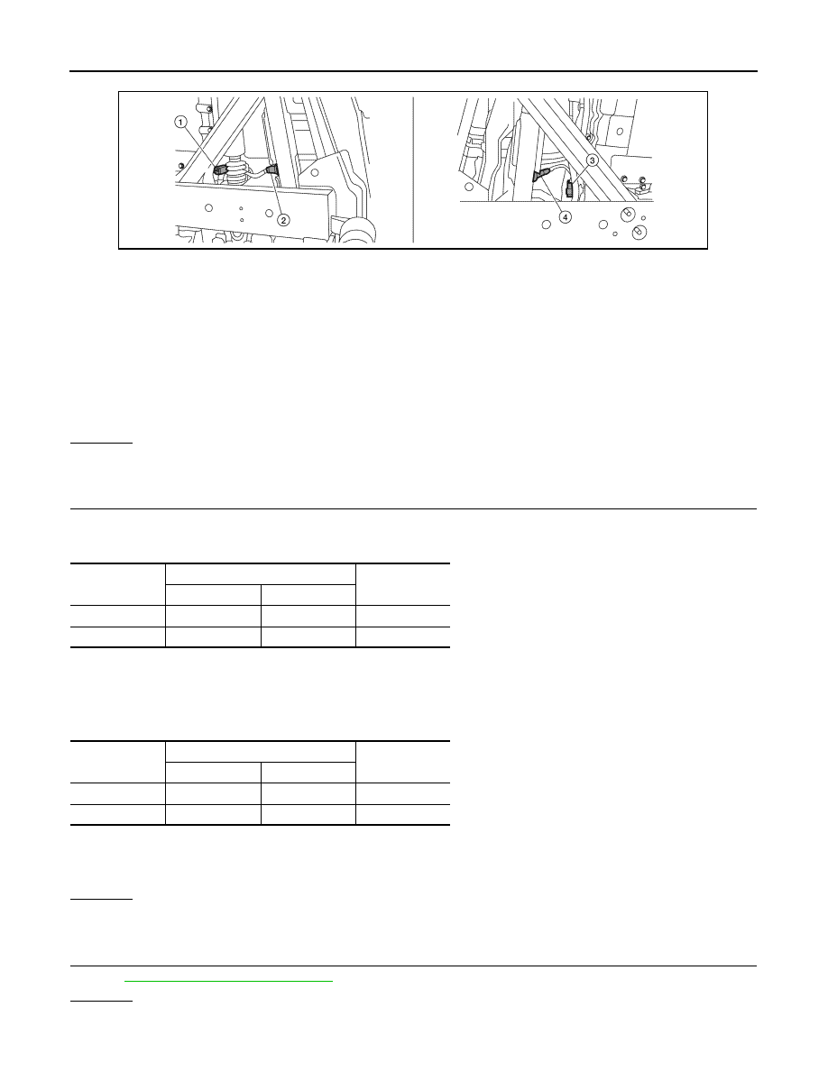
Heated oxygen sensor 2 (bank 1)
harness connector
2.
Heated oxygen sensor 2 (bank 1)
3.
Heated oxygen sensor 2 (bank 2)
harness connector
4.
Heated oxygen sensor 2 (bank 2)
Continuity should exist.
DTC
Terminals
Bank
ECM
Sensor
P0138
55
1
1
P0158
74
1
2
Continuity should exist.
DTC
Terminals
Bank
ECM
Sensor
P0138
55
1
1
P0158
74
1
2
Continuity should not exist.
Water should not exist.
August 2012
2012 Pathfinder
P0138, P0158 HO2S2
EC-703
< DTC/CIRCUIT DIAGNOSIS >
[VK56DE]
C
D
E
F
G
H
I
J
K
L
M
A
EC
N
P
O
GI-37, "Intermittent Incident"
.
>>
INSPECTION END
PROCEDURE FOR MALFUNCTION B
1.
CHECK GROUND CONNECTIONS
1. Turn ignition switch OFF.
2. Loosen and retighten ground screws on the body.
OK or NG
OK
>> GO TO 2.
NG
>> Repair or replace ground connections.
2.
CLEAR THE SELF-LEARNING DATA
With CONSULT
1. Start engine and warm it up to normal operating temperature.
2. Select “SELF-LEARNING CONT” in “WORK SUPPORT” mode with CONSULT.
3. Clear the self-learning control coefficient by touching “CLEAR”.
4. Run engine for at least 10 minutes at idle speed.
Is the 1st trip DTC P0172 or P0175 detected?
Is it difficult to start engine?
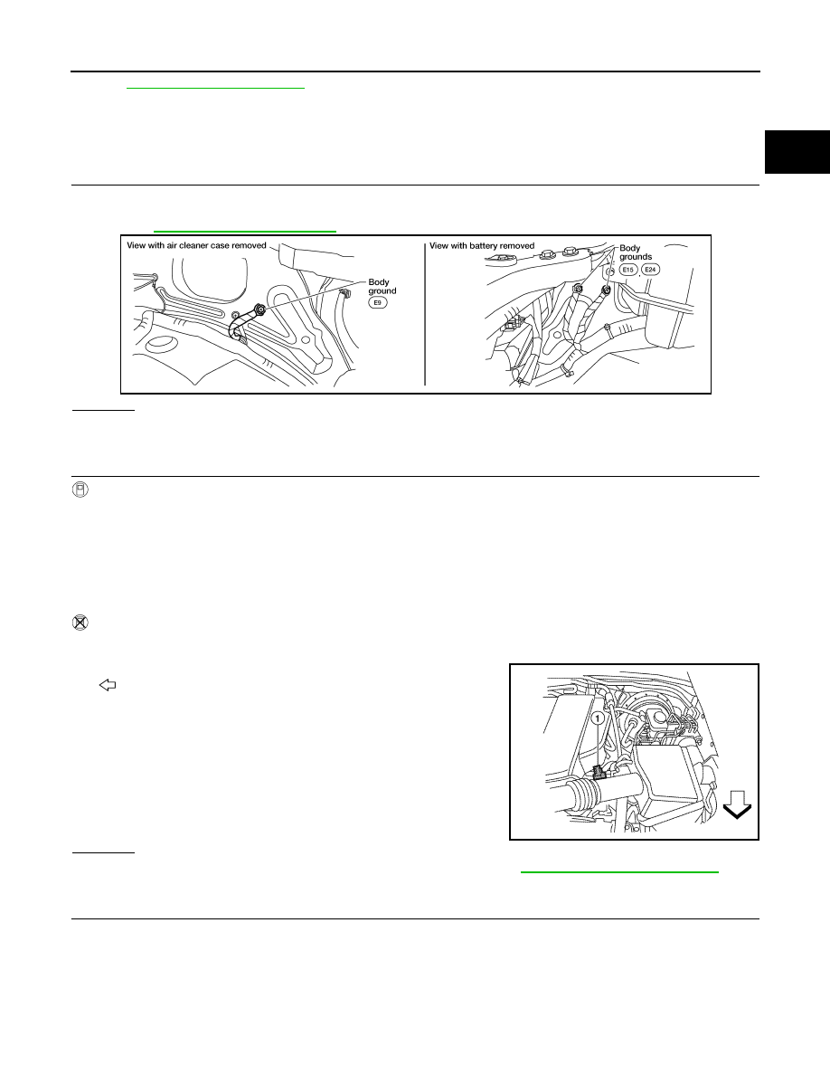
Without CONSULT
1. Start engine and warm it up to normal operating temperature.
2. Turn ignition switch OFF.
3. Disconnect mass air flow sensor (1) harness connector.
-
: Vehicle front
4. Restart engine and let it idle for at least 5 seconds.
5. Stop engine and reconnect mass air flow sensor harness con-
nector.
6. Check that DTC P0102 is displayed.
7. Erase the DTC memory.
8. Check that DTC P0000 is displayed.
9. Run engine for at least 10 minutes at idle speed.
Is the 1st trip DTC P0172 or P0175 detected?
Is it difficult to start engine?
Yes or No
Yes
>> Perform trouble diagnosis for DTC P0172, P0175. Refer to
.
No
>> GO TO 3.
3.
CHECK HEATED OXYGEN SENSOR 2 GROUND CIRCUIT FOR OPEN AND SHORT
1. Turn ignition switch OFF.
2. Disconnect heated oxygen sensor 2 (HO2S2) harness connector.
BBIA0539E
ALBIA0353ZZ
August 2012
2012 Pathfinder
EC-704
< DTC/CIRCUIT DIAGNOSIS >
[VK56DE]
P0138, P0158 HO2S2
3. Disconnect ECM harness connector.
4. Check harness continuity between ECM terminal 78 and HO2S2 terminal 4.
Refer to Wiring Diagram.
5. Also check harness for short to ground and short to power.
OK or NG
OK
>> GO TO 4.
NG
>> Repair open circuit or short to ground or short to power in harness or connectors.
4.
CHECK HO2S2 INPUT SIGNAL CIRCUIT FOR OPEN AND SHORT
1. Check harness continuity between ECM terminal and HO2S2 terminal as follows.
Refer to Wiring Diagram.
2. Check harness continuity between the following terminals and ground.
Refer to Wiring Diagram.
3. Also check harness for short to power.
OK or NG
OK
>> GO TO 5.
NG
>> Repair open circuit or short to ground or short to power in harness or connectors.
5.
CHECK HEATED OXYGEN SENSOR 2
EC-705, "Component Inspection"
OK or NG
OK
>> GO TO 6.
1.
Heated oxygen sensor 2 (bank 1)
harness connector
2.
Heated oxygen sensor 2 (bank 1)
3.
Heated oxygen sensor 2 (bank 2)
harness connector
4.
Heated oxygen sensor 2 (bank 2)
Continuity should exist.
ALBIA0365ZZ
DTC
Terminals
Bank
ECM
Sensor
P0138
55
1
1
P0158
74
1
2
Continuity should exist.
DTC
Terminals
Bank
ECM
Sensor
P0138
55
1
1
P0158
74
1
2
Continuity should not exist.
August 2012
2012 Pathfinder
Нет комментариевНе стесняйтесь поделиться с нами вашим ценным мнением.
Текст