Nissan Sentra. Instruction — part 416
EC-360
< DTC/CIRCUIT DIAGNOSIS >
[MRA8DE]
P1078 EVT CONTROL POSITION SENSOR
3.
CHECK EVT CONTROL POSITION SENSOR GROUND CIRCUIT
1. Turn ignition switch OFF.
2. Disconnect ECM harness connector.
3. Check the continuity between EVT control position sensor harness connector and ECM harness connec-
tor.
4. Also check harness for short to power.
Is the inspection result normal?
YES
>> GO TO 4.
NO
>> Repair or replace error-detected parts.
4.
CHECK EVT CONTROL POSITION SENSOR INPUT SIGNAL CIRCUIT
1. Disconnect ECM harness connector.
2. Check the continuity between EVT control position sensor harness connector and ECM harness connec-
tor.
3. Also check harness for short to ground and to power.
Is the inspection result normal?
YES
>> GO TO 5.
NO
>> Repair or replace error-detected parts.
5.
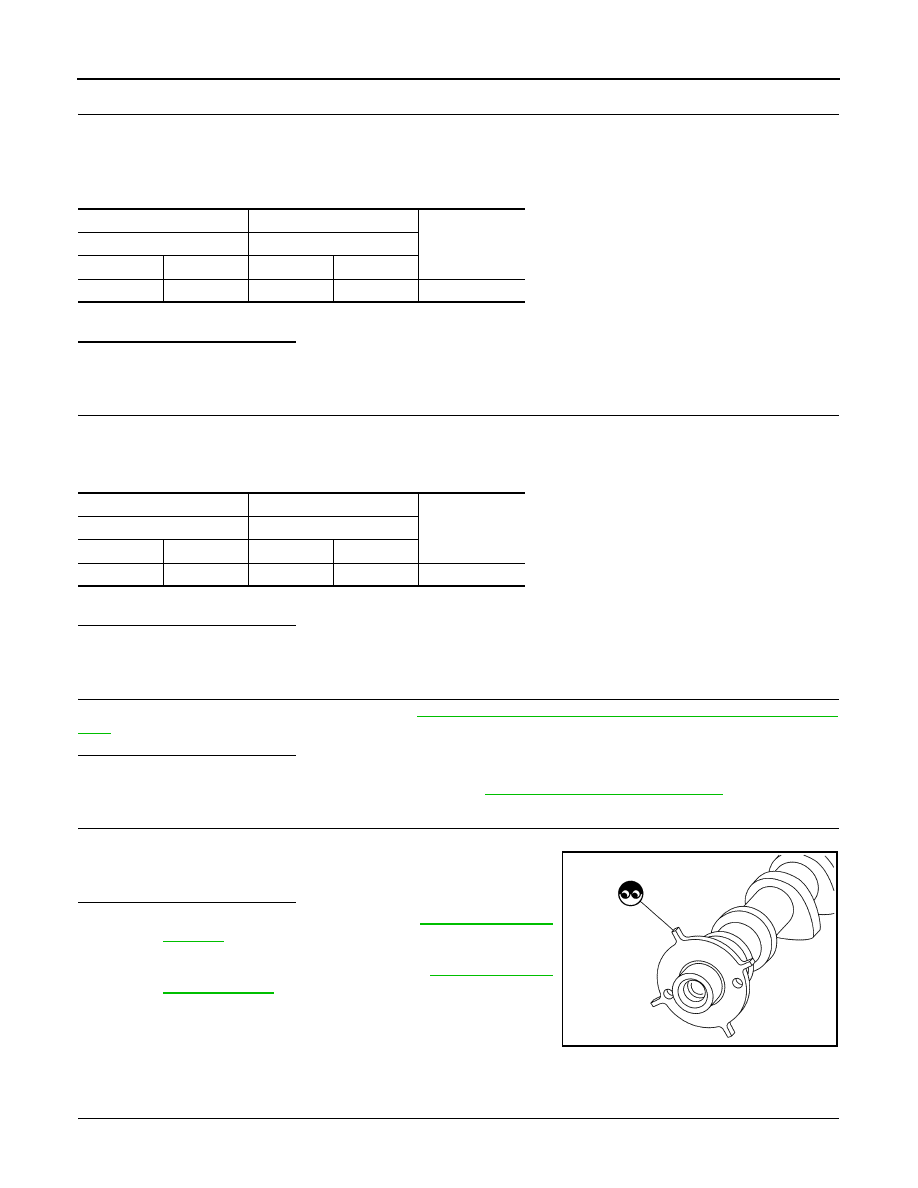
CHECK EVT CONTROL POSITION SENSOR
Check the EVT control position sensor. Refer to
EC-360, "Component Inspection (EVT Control Position Sen-
Is the inspection result normal?
YES
>> GO TO 6.
NO
>> Replace EVT control position sensor. Refer to
EM-60, "Removal and Installation"
.
6.
CHECK CAMSHAFT (EXT)
Check the following.
• Accumulation of debris to the signal plate of camshaft rear end
• Chipping signal plate of camshaft rear end
Is the inspection result normal?
YES
>> Check intermittent incident. Refer to
NO
>> Remove debris and clean the signal plate of camshaft
rear end or replace camshaft. Refer to
.
Component Inspection (EVT Control Position Sensor)
INFOID:0000000009758612
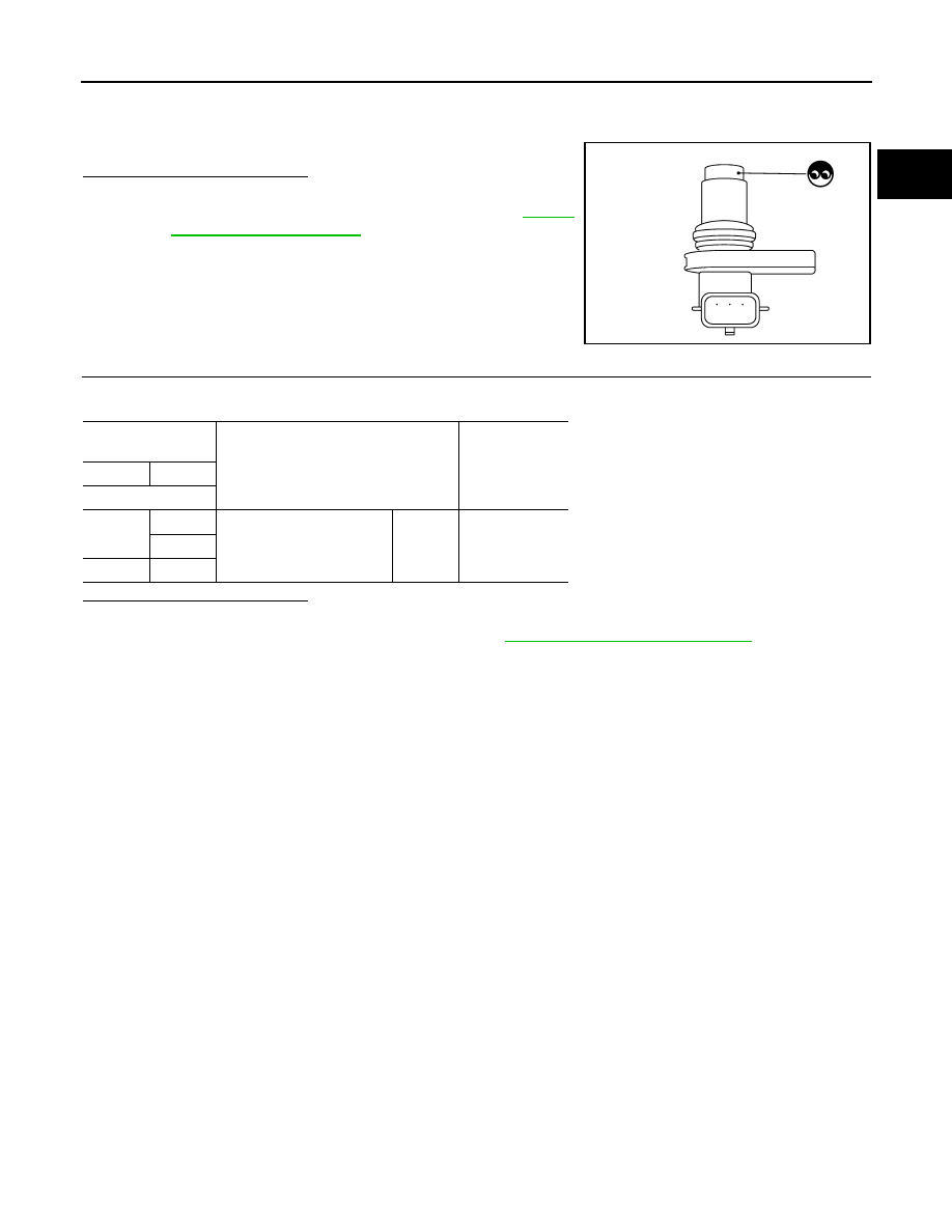
1.
EXHAUST VALVE TIMING (EVT) CONTROL POSITION SENSOR-1
1. Turn ignition switch OFF.
+
−
Continuity
EVT control position sensor
ECM
Connector
Terminal
Connector
Terminal
F57
2
F24
42
Existed
+
−
Continuity
EVT control position sensor
ECM
Connector
Terminal
Connector
Terminal
F57
3
F24
43
Existed
JSBIA0600ZZ
P1078 EVT CONTROL POSITION SENSOR
EC-361
< DTC/CIRCUIT DIAGNOSIS >
[MRA8DE]
C
D
E
F
G
H
I
J
K
L
M
A
EC
N
P
O
2. Disconnect EVT control position sensor harness connector.
3. Loosen the fixing bolt of the sensor.
4. Remove EVT control position sensor.
5. Visually check the sensor for chipping.
Is the inspection result normal?
YES
>> GO TO 2.
NO
>> Replace EVT control position sensor. Refer to
.
2.
EVT CONTROL POSITION SENSOR-2
Check resistance EVT control position sensor terminals as shown below.
Is the inspection result normal?
YES
>> INSPECTION END
NO
>> Replace EVT control position sensor. Refer to
EM-60, "Removal and Installation"
.
JMBIA0065ZZ
EVT control position
sensor
Condition
Resistance
+
−
Terminal
1
2
Temperature
°C (°F)
25 (77)
Except 0 or
∞ Ω
3
2
3

EC-362
< DTC/CIRCUIT DIAGNOSIS >
[MRA8DE]
P1148 CLOSED LOOP CONTROL
P1148 CLOSED LOOP CONTROL
DTC Logic
INFOID:0000000009758613
DTC DETECTION LOGIC
NOTE:
DTC P1148 is displayed with DTC for A/F sensor 1.
When the DTC is detected, perform the trouble diagnosis of DTC corresponding to A/F sensor 1.
Diagnosis Procedure
INFOID:0000000009758614
DTC P1148 is displayed with DTC for A/F sensor 1.
When the DTC is detected, perform the trouble diagnosis of DTC corresponding to A/F sensor 1.
.
DTC No.
CONSULT screen terms
(Trouble diagnosis content)
DTC detecting condition
Possible cause
P1148
CLOSED LOOP-B1
(CLOSED LOOP-B1)
The closed loop control function does not
operate even when vehicle is being driven in
the specified condition.
• Harness or connectors
(A/F sensor 1 circuit is open or shorted.)
• A/F sensor 1
• A/F sensor 1 heater

P117A AIR FUEL RATIO
EC-363
< DTC/CIRCUIT DIAGNOSIS >
[MRA8DE]
C
D
E
F
G
H
I
J
K
L
M
A
EC
N
P
O
P117A AIR FUEL RATIO
DTC Logic
INFOID:0000000009758615
DTC DETECTION LOGIC
NOTE:
If DTC P117A is displayed with other DTC, first perform the trouble diagnosis for the other DTC. Refer
DTC CONFIRMATION PROCEDURE
1.
PRECONDITIONING-1
If DTC Confirmation Procedure has been previously conducted, always perform the following before conduct-
ing the next test.
1. Turn ignition switch OFF and wait at least 10 seconds.
2. Turn ignition switch ON.
3. Turn ignition switch OFF and wait at least 10 seconds.
NOTE:
Before performing the following procedure, confirm that battery voltage is 11 V or more at idle.
>> GO TO 2.
2.
PRECONDITIONING-2
1. Turn ignition switch ON.
2. Clear the mixture ratio self-learning value. Refer to
.
Will CONSULT be used?
YES
>> GO TO 3.
NO
>> GO TO 6.
3.
PERFORM DTC CONFIRMATION PROCEDURE-1
1. Turn ignition switch ON.
2. Select “COOLANT TEMP/S” in “DATA MONITOR” mode of “ENGINE” using CONSULT.
3. Start engine.
4. Make sure that “COOLANT TEMP/S” indicates more than 80
°C (176°F).
>> GO TO 4.
4.
PERFORM DTC CONFIRMATION PROCEDURE-2
With CONSULT
1. Select “SYSTEM 1 DIAGNOSIS B B1” and “SYSTEM 1 DIAGNOSIS A B1” in “DATA MONITOR” mode of
“ENGINE” using CONSULT.
2. Drive vehicle under the following conditions for at least 5 consecutive seconds.
CAUTION:
DTC No.
CONSULT screen terms
(Trouble diagnosis content)
DTC detecting condition
Possible cause
P117A
AIR FUEL RATIO B1
(AIR FUEL RATIO B1)
ECM detects a lean/rich air fuel ratio state in any
cylinder for a specified length of time.
• Fuel injector
• Exhaust gas leaks
• Incorrect fuel pressure
• Mass air flow sensor
• Intake air leaks
• Lack of fuel
• Incorrect PCV hose connection
• Improper spark plug
• Insufficient compression
• The fuel injector circuit is open or
shorted
• ignition coil
• The ignition signal circuit is open or
shorted
Нет комментариевНе стесняйтесь поделиться с нами вашим ценным мнением.
Текст