Nissan Sentra. Instruction — part 372

EC-184
< DTC/CIRCUIT DIAGNOSIS >
[MRA8DE]
P0078 EVT CONTROL SOLENOID VALVE
4. Also check harness for short to ground.
Is the inspection result normal?
YES
>> Perform the trouble diagnosis for power supply circuit.
NO
>> Repair or replace error-detected parts.
3.
CHECK EXHAUST VALVE TIMING CONTROL SOLENOID VALVE GROUND CIRCUIT
1. Turn ignition switch OFF.
2. Disconnect ECM harness connector.
3. Check the continuity between EVT control solenoid valve harness connector and ECM harness connec-
tor.
4. Also check harness for short to ground and to power.
Is the inspection result normal?
YES
>> GO TO 4.
NO
>> Repair or replace error-detected parts.
4.
CHECK EXHAUST VALVE TIMING CONTROL SOLENOID VALVE
Check the exhaust valve timing control solenoid valve. Refer to
EC-181, "Component Inspection (IVT Control
Is the inspection result normal?
YES
>> Check intermittent incident. Refer to
GI-39, "Intermittent Incident"
.
NO
>> Replace exhaust valve timing control solenoid valve. Refer to
EM-49, "Removal and Installation"
Component Inspection (EVT Control Solenoid Valve)
INFOID:0000000009758445
1.
CHECK EXHAUST VALVE TIMING CONTROL SOLENOID VALVE-1
1. Turn ignition switch OFF.
2. Disconnect exhaust valve timing control solenoid valve harness connector.
3. Check resistance between exhaust valve timing control solenoid valve terminals as per the following.
Is the inspection result normal?
YES
>> GO TO 2.
NO
>> Replace exhaust valve timing control solenoid valve. Refer to
EM-49, "Removal and Installation"
2.
CHECK EXHAUST VALVE TIMING CONTROL SOLENOID VALVE-2
1. Remove exhaust valve timing control solenoid valve. Refer to
.
+
+
Continuity
EVT control solenoid valve
IPDM E/R
Connector
Terminal
Connector
Terminal
F55
1
E45
26
Existed
+
+
Continuity
EVT control solenoid valve
ECM
Connector
Terminal
Connector
Terminal
F55
2
F25
94
Existed
Exhaust valve timing control
solenoid valve
Resistance
+
−
Terminal
1
2
7.0 - 7.8
Ω [at 20°C (68°F)]
1
Ground
∞ Ω
(Continuity should not exist)
2
P0078 EVT CONTROL SOLENOID VALVE
EC-185
< DTC/CIRCUIT DIAGNOSIS >
[MRA8DE]
C
D
E
F
G
H
I
J
K
L
M
A
EC
N
P
O
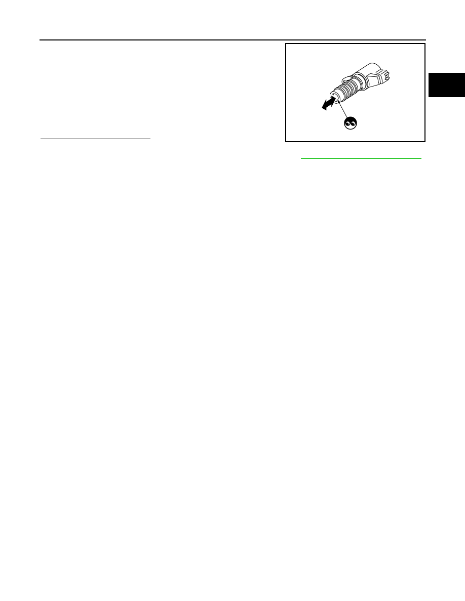
2. Provide 12 V DC between exhaust valve timing control solenoid
valve terminals 1 and 2, and then interrupt it. Check that the
plunger moves as shown in the figure.
CAUTION:
Do not apply 12 V DC continuously for 5 seconds or more.
Doing so may result in damage to the coil in exhaust valve
timing control solenoid valve.
NOTE:
Always replace O-ring when exhaust valve timing control
solenoid valve is removed.
Is the inspection result normal?
YES
>> INSPECTION END
NO
>> Replace exhaust valve timing control solenoid valve. Refer to
EM-49, "Removal and Installation"
JMBIA0079ZZ

EC-186
< DTC/CIRCUIT DIAGNOSIS >
[MRA8DE]
P0101, P0102, P0103 MAF SENSOR
P0101, P0102, P0103 MAF SENSOR
DTC Logic
INFOID:0000000009758446
DTC DETECTION LOGIC
DTC CONFIRMATION PROCEDURE
1.
PRECONDITIONING
If DTC Confirmation Procedure has been previously conducted, always perform the following procedure
before conducting the next test.
1. Turn ignition switch OFF and wait at least 10 seconds.
2. Turn ignition switch ON.
3. Turn ignition switch OFF and wait at least 10 seconds.
Which DTC is detected?
P0102 >> GO TO 2.
P0101 or P0103>>GO TO 3.
2.
PERFORM DTC CONFIRMATION PROCEDURE FOR DTC P0102
1. Start engine and wait at least 5 seconds.
2. Check DTC.
Is DTC detected?
YES
>> Proceed to
.
NO
>> INSPECTION END
3.
PERFORM DTC CONFIRMATION PROCEDURE FOR DTC P0101 AND P0103-1
1. Turn ignition switch ON and wait at least 5 seconds.
2. Check DTC.
Is DTC detected?
YES
>> Proceed to
.
NO
>> GO TO 4.
4.
PERFORM DTC CONFIRMATION PROCEDURE FOR DTC P0101 AND P0103-2
1. Start engine and wait at least 5 seconds.
2. Check DTC.
Is DTC detected?
YES
>> Proceed to
.
NO
>> INSPECTION END
DTC No.
CONSULT screen terms
(Trouble diagnosis content)
DTC detecting condition
Possible cause
P0101
MAF SEN/CIRCUIT-B1
(Mass or volume air flow “A”
circuit range/performance)
An excessively high voltage from the mass air
flow sensor is sent to ECM.
• Harness or connectors
(Mass air flow sensor circuit is open or
shorted.)
• Mass air flow sensor
• Sensor power supply 2 circuit
P0102
MAF SEN/CIRCUIT-B1
(Mass or volume air flow “A”
circuit low input)
An excessively low voltage from the mass air
flow sensor is sent to ECM.
• Harness or connectors
(Mass air flow sensor circuit is open or
shorted.)
• Intake air leaks
• Mass air flow sensor
• Sensor power supply 2 circuit
P0103
MAF SEN/CIRCUIT-B1
(Mass or volume air flow “A”
circuit high input)
An excessively high voltage from the mass air
flow sensor is sent to ECM.
• Harness or connectors
(Mass air flow sensor circuit is open or
shorted.)
• Mass air flow sensor
• Sensor power supply 2 circuit

P0101, P0102, P0103 MAF SENSOR
EC-187
< DTC/CIRCUIT DIAGNOSIS >
[MRA8DE]
C
D
E
F
G
H
I
J
K
L
M
A
EC
N
P
O
Diagnosis Procedure
INFOID:0000000009758447
1.
INSPECTION START
Confirm the detected DTC.
Which DTC is detected?
P0102 >> GO TO 2.
P0101 and P0103>>GO TO 3.
2.
CHECK INTAKE SYSTEM
Check the following for connection.
• Air duct
• Vacuum hoses
• Intake air passage between air duct to intake manifold
Is the inspection result normal?
YES
>> GO TO 3.
NO
>> Reconnect or replace error-detected parts.
3.
CHECK MASS AIR FLOW (MAF) SENSOR POWER SUPPLY
1. Turn ignition switch OFF.
2. Disconnect MAF sensor harness connector.
3. Turn ignition switch ON.
4. Check the voltage between MAF sensor harness connector and ground.
Is the inspection result normal?
YES
>> GO TO 4.
NO
>> GO TO 7.
4.
CHECK MAF SENSOR GROUND CIRCUIT
1. Turn ignition switch OFF.
2. Disconnect ECM harness connector.
3. Check the continuity between MAF sensor harness connector and ECM harness connector.
4. Also check harness for short to power.
Is the inspection result normal?
YES
>> GO TO 5.
NO
>> Repair or replace error-detected parts.
5.
CHECK MAF SENSOR INPUT SIGNAL CIRCUIT
1. Check the continuity between MAF sensor harness connector and ECM harness connector.
2. Also check harness for short to ground and short to power.
+
−
Voltage
(Approx.)
MAF sensor
Connector
Terminal
F31
1
Ground
5 V
+
−
Continuity
MAF sensor
ECM
Connector
Terminal
Connector
Terminal
F31
2
F24
34
Existed
+
−
Continuity
MAF sensor
ECM
Connector
Terminal
Connector
Terminal
F31
3
F24
35
Existed
Нет комментариевНе стесняйтесь поделиться с нами вашим ценным мнением.
Текст