Nissan Sentra. Instruction — part 474
TURN SIGNAL LAMP CIRCUIT
EXL-99
< DTC/CIRCUIT DIAGNOSIS >
C
D
E
F
G
H
I
J
K
M
A
B
EXL
N
O
P
TURN SIGNAL LAMP CIRCUIT
Description
INFOID:0000000009757522
The BCM monitors inputs from the combination switch to determine when to activate the turn signals. The
BCM outputs voltage direction to the left and right turn signals during turn signal operation or both during haz-
ard warning operation. The BCM sends a turn signal indicator request to the combination meter via the CAN
communication lines.
The BCM performs the fast flasher operation (fail-safe) if any bulb or harness of the turn signal lamp circuit is
open.
NOTE:
Turn signal lamp blinks at normal speed when using the hazard warning lamp.
Component Function Check
INFOID:0000000009757523
1.
CHECK TURN SIGNAL LAMP
CONSULT
1. Select FLASHER of BCM (FLASHER) active test item.
2. With operating the test items, check that the turn signal lamp blinks.
Does the turn signal lamp blink?
YES
>> Turn signal lamp circuit is normal.
NO
>> Refer to
.
Diagnosis Procedure
INFOID:0000000009757524
Regarding Wiring Diagram information, refer to
.
1.
CHECK TURN SIGNAL LAMP BULB
Check the applicable lamp bulb to be sure the proper bulb standard is in use and the bulb is not open.
Is the bulb OK?
YES
>> GO TO 2.
NO
>> Replace the bulb.
2.
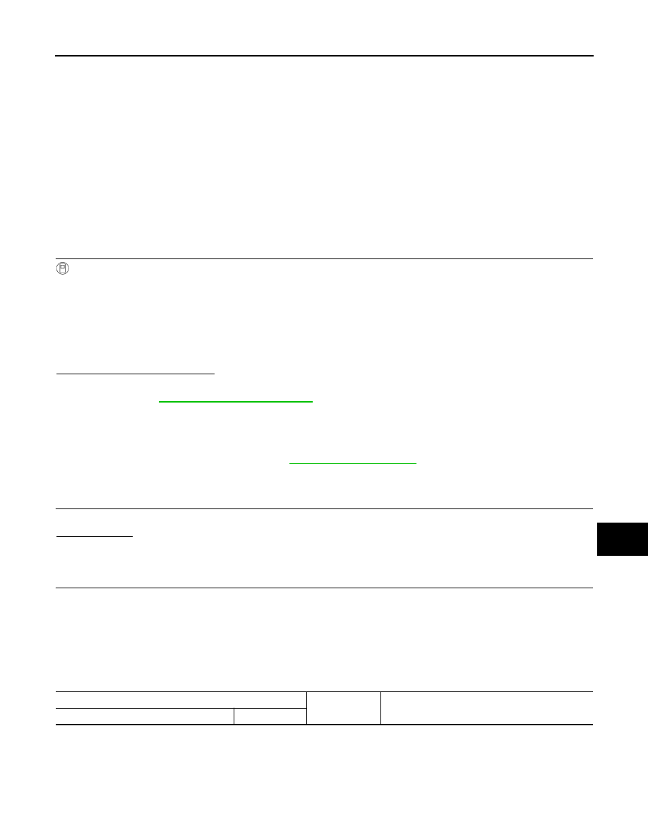
CHECK TURN SIGNAL LAMP OUTPUT VOLTAGE
1. Turn the ignition switch OFF.
2. Disconnect the front or rear combination lamp harness connector or the door mirror harness connector (if
equipped with turn signal in mirror) in question.
3. Turn the ignition switch ON.
4. Operate the turn signal switch.
5. While the turn signal is operating, check the voltage between the front combination lamp harness connec-
tor and ground.
LH
: Turn signal lamps (LH) ON
RH
: Turn signal lamps (RH) ON
OFF
: The turn signal lamps OFF
(+)
(
−)
Voltage
(Approx.)
Connector
Terminal
EXL-100
< DTC/CIRCUIT DIAGNOSIS >
TURN SIGNAL LAMP CIRCUIT
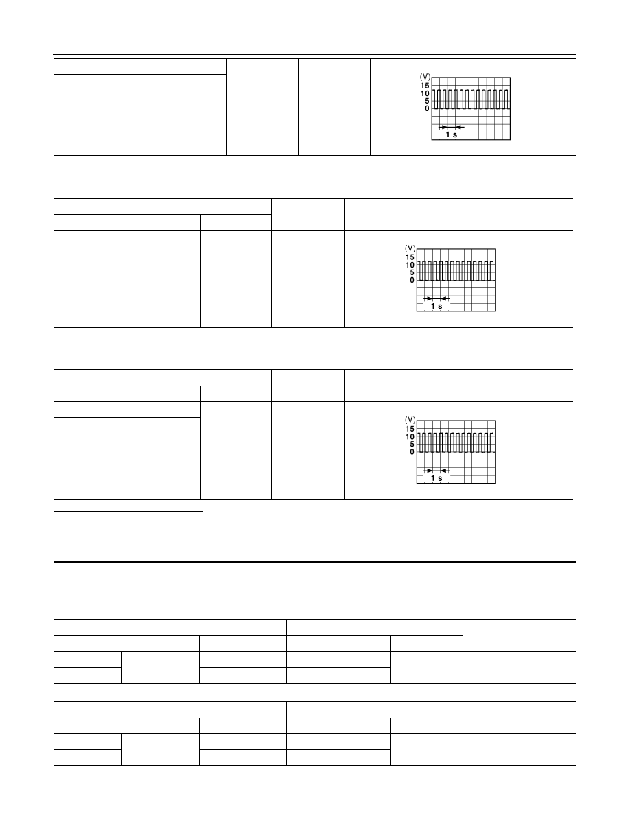
6. While the turn signal is operating, check the voltage between the rear combination lamp harness connec-
tor and ground.
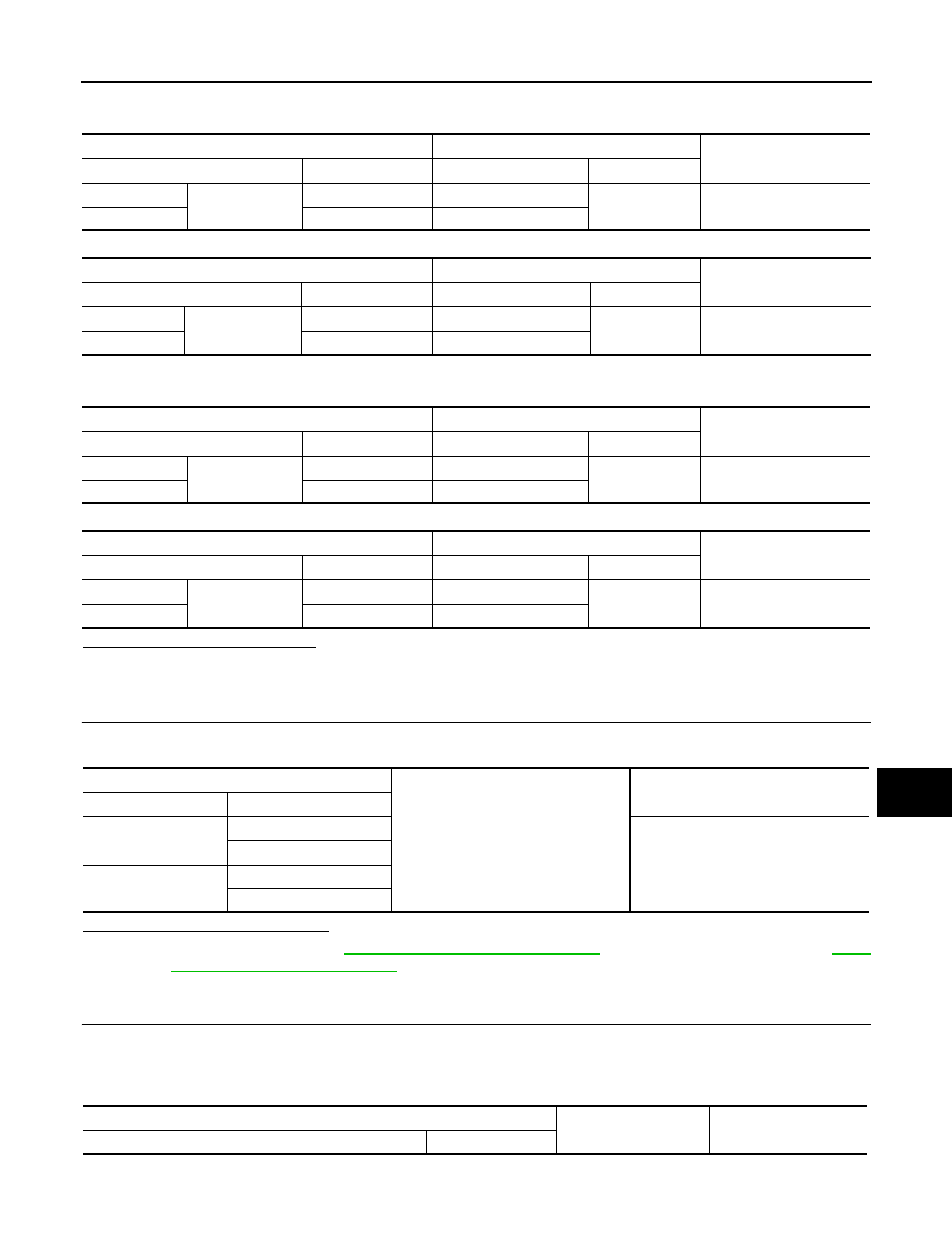
7. While the turn signal is operating, check the voltage between the door mirror harness connector and
ground.
Is the inspection result normal?
YES
>> GO TO 5.
NO
>> GO TO 3.
3.
CHECK TURN SIGNAL LAMP CIRCUIT FOR OPEN
1. Turn the ignition switch OFF.
2. Disconnect BCM harness connector in question.
3. Check continuity between the BCM harness connector and the front combination lamp harness connector.
With Intelligent Key
Without Intelligent Key
RH
E20
4
Ground
LH
E21
PKID0926E
(+)
(
−)
Voltage
(Approx.)
Connector
Terminal
RH
B42
4
Ground
LH
B25
(+)
(
−)
Voltage
(Approx.)
Connector
Terminal
RH
D106
10
Ground
LH
D7
PKID0926E
PKID0926E
BCM
Front combination lamp
Continuity
Connector
Terminal
Connector
Terminal
LH
M85
85
E21
4
Yes
RH
84
E20
BCM
Front combination lamp
Continuity
Connector
Terminal
Connector
Terminal
LH
B57
41
E21
4
Yes
RH
42
E20
TURN SIGNAL LAMP CIRCUIT
EXL-101
< DTC/CIRCUIT DIAGNOSIS >
C
D
E
F
G
H
I
J
K
M
A
B
EXL
N
O
P
4. Check continuity between the BCM harness connector and the rear combination lamp harness connector.
With Intelligent Key
Without Intelligent Key
5. Check continuity between the BCM harness connector and the door mirror harness connector in question.
With Intelligent Key
Without Intelligent Key
Is the inspection results normal?
YES
>> GO TO 4.
NO
>> Repair or replace the harness or connectors.
4.
CHECK TURN SIGNAL LAMP SHORT CIRCUIT
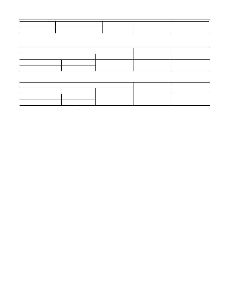
1. Check continuity between the BCM harness connector and ground.
Are the inspection results normal?
YES
>> Replace BCM. Refer to
BCS-73, "Removal and Installation"
(with Intelligent Key system) or
126, "Removal and Installation"
(without Intelligent Key system).
NO
>> Repair or replace the harness or connectors.
5.
CHECK TURN SIGNAL LAMP GROUND CIRCUIT
1. Turn the ignition switch OFF.
2. Check continuity between the front combination lamp harness connector or the rear combination lamp
harness connector or the door mirror harness connector in question and ground.
BCM
Rear combination lamp
Continuity
Connector
Terminal
Connector
Terminal
LH
M85
85
B25
4
Yes
RH
84
B42
BCM
Rear combination lamp
Continuity
Connector
Terminal
Connector
Terminal
LH
B57
41
B25
4
Yes
RH
42
B42
BCM
Rear combination lamp
Continuity
Connector
Terminal
Connector
Terminal
LH
M85
85
D7
10
Yes
RH
84
D106
BCM
Rear combination lamp
Continuity
Connector
Terminal
Connector
Terminal
LH
B57
41
D7
10
Yes
RH
42
D106
BCM
Ground
Continuity
Connector
Terminal
M85 (with Intelligent
Key)
84
No
85
B57 (without Intelli-
gent Key)
41
42
Front combination lamp
(
−)
Continuity
Connector
Terminal
EXL-102
< DTC/CIRCUIT DIAGNOSIS >
TURN SIGNAL LAMP CIRCUIT
3. Check continuity between the rear combination lamp harness connector and ground.
4. Check continuity between the door mirror harness connector and ground.
Are the inspection results normal?
YES
>> Replace the malfunctioning lamp.
NO
>> Repair or replace the harness or connectors.
LH
E21
7
Ground
Yes
RH
E20
Rear combination lamp
(
−)
Continuity
Connector
Terminal
LH
B25
6
Ground
Yes
RH
B42
Door mirror
(
−)
Continuity
Connector
Terminal
LH
D7
8
Ground
Yes
RH
D106
Нет комментариевНе стесняйтесь поделиться с нами вашим ценным мнением.
Текст