Nissan Sentra. Instruction — part 423

EC-388
< DTC/CIRCUIT DIAGNOSIS >
[MRA8DE]
P1564 ASCD STEERING SWITCH
P1564 ASCD STEERING SWITCH
DTC Logic
INFOID:0000000009758643
DTC DETECTION LOGIC
NOTE:
If DTC P1564 is displayed with DTC P0605, first perform the trouble diagnosis for DTC P0605. Refer to
DTC CONFIRMATION PROCEDURE
1.
PRECONDITIONING
If DTC Confirmation Procedure has been previously conducted, always perform the following procedure
before conducting the next test.
1. Turn ignition switch OFF and wait at least 10 seconds.
2. Turn ignition switch ON.
3. Turn ignition switch OFF and wait at least 10 seconds.
>> GO TO 2.
2.
PERFORM DTC CONFIRMATION PROCEDURE
1. Turn ignition switch ON.
2. Wait at least 10 seconds.
3. Press MAIN switch for at least 10 seconds, then release it and wait at least 10 seconds.
4. Press CANCEL switch for at least 10 seconds, then release it and wait at least 10 seconds.
5. Press ACCEL/RES switch for at least 10 seconds, then release it and wait at least 10 seconds.
6. Press COAST/SET switch for at least 10 seconds, then release it and wait at least 10 seconds.
7. Check DTC.
Is DTC detected?
YES
>> Proceed to
.
NO
>> INSPECTION END
Diagnosis Procedure
INFOID:0000000009758644
1.
CHECK ASCD STEERING SWITCH CIRCUIT
With CONSULT
1. Turn ignition switch ON.
2. Select “CANCEL SW”, “RESUME/ACC SW” and “SET SW” in “DATA MONITOR” mode of “ENGINE”
using CONSULT.
3. Check each item indication as per the following conditions.
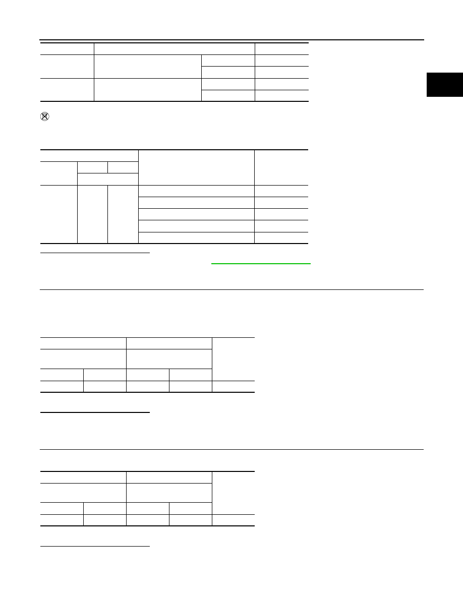
DTC No.
CONSULT screen terms
(Trouble diagnosis content)
DTC detecting condition
Possible cause
P1564
ASCD SW
(ASCD SW)
• An excessively high voltage signal from the
ASCD steering switch is sent to ECM.
• ECM detects that input signal from the
ASCD steering switch is out of the specified
range.
• ECM detects that the ASCD steering switch
is stuck ON.
• Harness or connectors
(ASCD steering switch circuit is open
or shorted.)
• ASCD steering switch
• ECM
Monitor item
Condition
Indication
MAIN SW
MAIN switch
Pressed
ON
Released
OFF
CANCEL SW
CANCEL switch
Pressed
ON
Released
OFF
P1564 ASCD STEERING SWITCH
EC-389
< DTC/CIRCUIT DIAGNOSIS >
[MRA8DE]
C
D
E
F
G
H
I
J
K
L
M
A
EC
N
P
O
Without CONSULT
1. Turn ignition switch ON.
2. Check the voltage between ECM harness connector terminals.
Is the inspection result normal?
YES
>> Check intermittent incident. Refer to
GI-39, "Intermittent Incident"
.
NO
>> GO TO 2.
2.
CHECK ASCD STEERING SWITCH GROUND CIRCUIT
1. Turn ignition switch OFF.
2. Disconnect ECM harness connector.
3. Disconnect combination switch (spiral cable) harness connector.
4. Check the continuity between combination switch (spiral cable) and ECM harness connector.
5. Also check harness for short to ground and to power.
Is the inspection result normal?
YES
>> GO TO 3.
NO
>> Repair or replace error-detected parts.
3.
CHECK ASCD STEERING SWITCH INPUT SIGNAL CIRCUIT
1. Check the continuity between ECM harness connector and combination switch.
2. Also check harness for short to ground and to power.
Is the inspection result normal?
YES
>> GO TO 4.
NO
>> Repair or replace error-detected parts.
RESUME/ACC
SW
ACCEL/RES switch
Pressed
ON
Released
OFF
SET SW
COAST/SET switch
Pressed
ON
Released
OFF
Monitor item
Condition
Indication
ECM
Condition
Voltage
(Approx.)
Connector
+
-
Terminal
E16
110
111
MAIN switch: Pressed
0 V
CANCEL switch: Pressed
1 V
COAST/SET switch: Pressed
2 V
ACCEL/RES switch: Pressed
3 V
All ASCD steering switches: Released
4 V
+
−
Continuity
Combination switch
(Spiral cable)
ECM
Connector
Terminal
Connector
Terminal
M80
22
E16
111
Existed
+
−
Continuity
Combination switch
(Spiral cable)
ECM
Connector
Terminal
Connector
Terminal
M80
27
E16
110
Existed
EC-390
< DTC/CIRCUIT DIAGNOSIS >
[MRA8DE]
P1564 ASCD STEERING SWITCH
4.
CHECK ASCD STEERING SWITCH
EC-390, "Component Inspection"
Is the inspection result normal?
YES
>> Check intermittent incident. Refer to
GI-39, "Intermittent Incident"
.
NO
>> Replace ASCD steering switch. Refer to
EC-15, "ENGINE CONTROL SYSTEM :
.
Component Inspection
INFOID:0000000009758645
1.
CHECK ASCD STEERING SWITCH
1. Disconnect combination switch (spiral cable) harness connector.
2. Check the resistance between combination switch harness connector terminals as per the following condi-
tions.
Is the inspection result normal?
YES
>> INSPECTION END
NO
>> Replace ASCD steering switch. Refer to
EC-15, "ENGINE CONTROL SYSTEM :
.
Combination switch
(Spiral cable)
Condition
Resistance
(Approx.)
Connector
+
−
Terminals
M108
1
3
MAIN switch: Pressed
0
Ω
CANCEL switch: Pressed
250
Ω
COAST/SET switch: Pressed
660
Ω
ACCEL/RES switch: Pressed
1,480
Ω
All ASCD steering switches: Released
4,000
Ω

P1572 ASCD BRAKE SWITCH
EC-391
< DTC/CIRCUIT DIAGNOSIS >
[MRA8DE]
C
D
E
F
G
H
I
J
K
L
M
A
EC
N
P
O
P1572 ASCD BRAKE SWITCH
DTC Logic
INFOID:0000000009758646
DTC DETECTION LOGIC
NOTE:
• If DTC P1572 is displayed with DTC P0605, first perform the trouble diagnosis for DTC P0605. Refer
.
• This self-diagnosis has the one trip detection logic. When malfunction A is detected, DTC is not
stored in ECM memory. And in that case, 1st trip DTC and 1st trip freeze frame data are displayed.
1st trip DTC is erased when ignition switch OFF. And even when malfunction A is detected in two
consecutive trips, DTC is not stored in ECM memory.
DTC CONFIRMATION PROCEDURE
1.
PRECONDITIONING
If DTC Confirmation Procedure has been previously conducted, always perform the following procedure
before conducting the next test.
1. Turn ignition switch OFF and wait at least 10 seconds.
2. Turn ignition switch ON.
3. Turn ignition switch OFF and wait at least 10 seconds.
NOTE:
Procedure for malfunction B is not described here. It takes extremely long time to complete procedure for mal-
function B. By performing procedure for malfunction A, the incident that causes malfunction B can be
detected.
>> GO TO 2.
2.
PERFORM DTC CONFIRMATION PROCEDURE FOR MALFUNCTION A
1. Start engine.
2. Press MAIN switch and make sure that CRUISE indicator is displayed in combination meter.
3. Drive the vehicle for at least 5 consecutive seconds as per the following conditions.
CAUTION:
Always drive vehicle at a safe speed.
NOTE:
This procedure may be conducted with the drive wheels lifted in the shop or by driving the vehicle.
If a road test is expected to be easier, it is unnecessary to lift the vehicle.
4. Check DTC.
Is DTC detected?
YES
>> Proceed to
.
NO
>> GO TO 3.
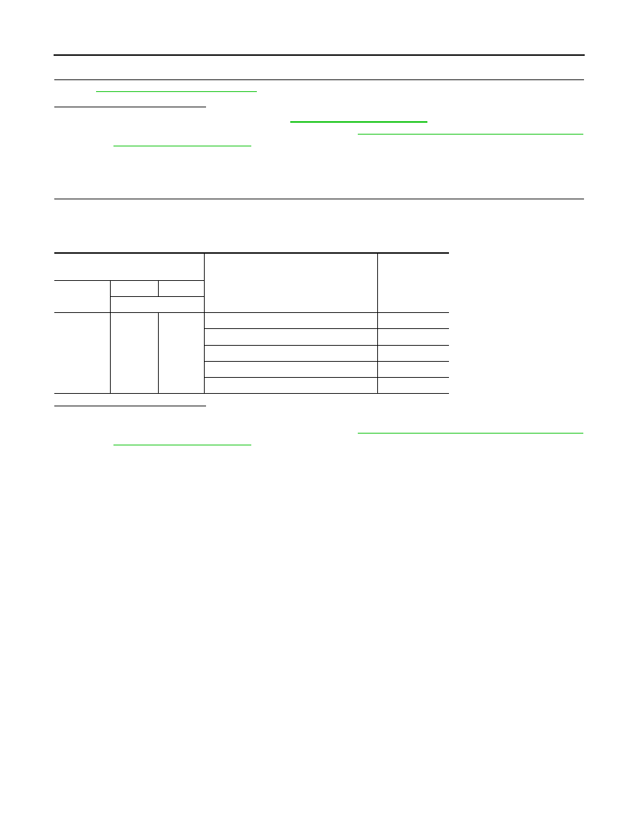
DTC No.
CONSULT screen terms
(Trouble diagnosis content)
DTC detecting condition
Possible cause
P1572
ASCD BRAKE SW
(ASCD BRAKE SW)
A)
When the vehicle speed is above 30 km/
h (19 MPH), ON signals from the stop
lamp switch and the brake pedal position
switch are sent to the ECM at the same
time.
• Harness or connectors
(Stop lamp switch circuit is shorted.)
(Brake pedal position switch circuit is
shorted.)
• Stop lamp switch
• Brake pedal position switch
• Stop lamp relay
• Incorrect stop lamp switch installation
• Incorrect brake pedal position switch in-
stallation
• ECM
B)
Brake pedal position switch signal is not
sent to ECM for extremely long time while
the vehicle is driving.
Vehicle speed
More than 30 km/h (19 mph)
Selector lever
Suitable position
Нет комментариевНе стесняйтесь поделиться с нами вашим ценным мнением.
Текст