Nissan Sentra. Instruction — part 652
MWI-54
< DTC/CIRCUIT DIAGNOSIS >
POWER SUPPLY AND GROUND CIRCUIT
NO
>> GO TO 2.
2.
CHECK POWER SUPPLY CIRCUIT
1. Turn ignition switch OFF.
2. Disconnect BCM connectors.
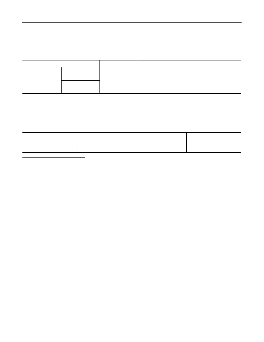
3. Check voltage between BCM connector and ground.
Is the inspection result normal?
YES
>> GO TO 3.
NO
>> Repair harness or connector.
3.
CHECK GROUND CIRCUIT
Check continuity between BCM connector and ground.
Is the inspection result normal?
YES
>> Inspection End.
NO
>> Repair harness or connector.
BCM
Ground
Ignition switch position
Connector
Terminal
OFF
ACC
ON
M20
63
Battery voltage
Battery voltage
Battery voltage
70
M21
11
—
0 V
Battery voltage
Battery voltage
BCM
Ground
Continuity
Connector
Terminal
M20
65
—
Yes
MWI
STEERING SWITCH (METER CONTROL SWITCH) SIGNAL CIRCUIT
MWI-55
< DTC/CIRCUIT DIAGNOSIS >
C
D
E
F
G
H
I
J
K
L
M
B
A
O
P
STEERING SWITCH (METER CONTROL SWITCH) SIGNAL CIRCUIT
Diagnosis Procedure
INFOID:0000000009758278
Regarding Wiring Diagram information, refer to
.
1.
CHECK COMBINATION METER INPUT SIGNAL
1. Turn ignition switch ON.
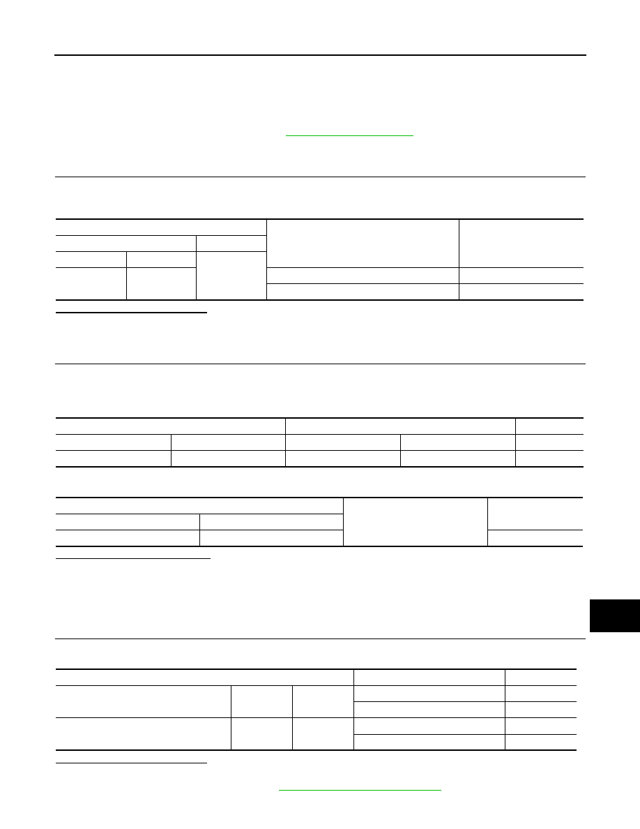
2. Measure voltage between the following terminals of the combination meter.
Is the inspection result normal?
YES
>> Inspection End.
NO
>> GO TO 2.
2.
CHECK STEERING SWITCH SIGNAL CIRCUIT
1. Turn ignition switch OFF.
2. Disconnect combination meter connector M24 and combination switch connector M80.
3. Check continuity between combination meter harness connector and steering switch harness connector.
4. Check continuity between combination meter harness connector and ground.
Is the inspection result normal?
YES
>> Inspection End.
NO
>> Repair or replace harness or connector.
Component Inspection
INFOID:0000000009758279
1.
CHECK STEERING SWITCH
Check continuity between spiral cable terminals.
Is the inspection result normal?
YES
>> Inspection End.
NO
>> Replace steering switch. Refer to
ST-10, "Removal and Installation"
.
Terminals
Condition
Voltage
(Approx.)
Combination meter
(
−)
Connector
(+)
Ground
M24
12
When meter control switch is pressed
0 V
Other than the above
5 V
Combination meter
Combination switch
Continuity
Connector
Terminal
Connector
Terminal
M24
12
M80
32
Yes
Combination meter
Ground
Continuity
Connector
Terminal
M24
12
No
Terminals
Condition
Continuity
Steering switch
(with audio steering switches)
17
16
When steering switch is pressed
Yes
Other than the above
No
Steering switch
(without audio steering switches)
13
16
When steering switch is pressed
Yes
Other than the above
No
MWI-56
< DTC/CIRCUIT DIAGNOSIS >
ILLUMINATION CONTROL SWITCH SIGNAL CIRCUIT
ILLUMINATION CONTROL SWITCH SIGNAL CIRCUIT
Diagnosis Procedure
INFOID:0000000009758280
Regarding Wiring Diagram information, refer to
.
1.
CHECK COMBINATION METER INPUT SIGNAL
1. Turn ignition switch ON.
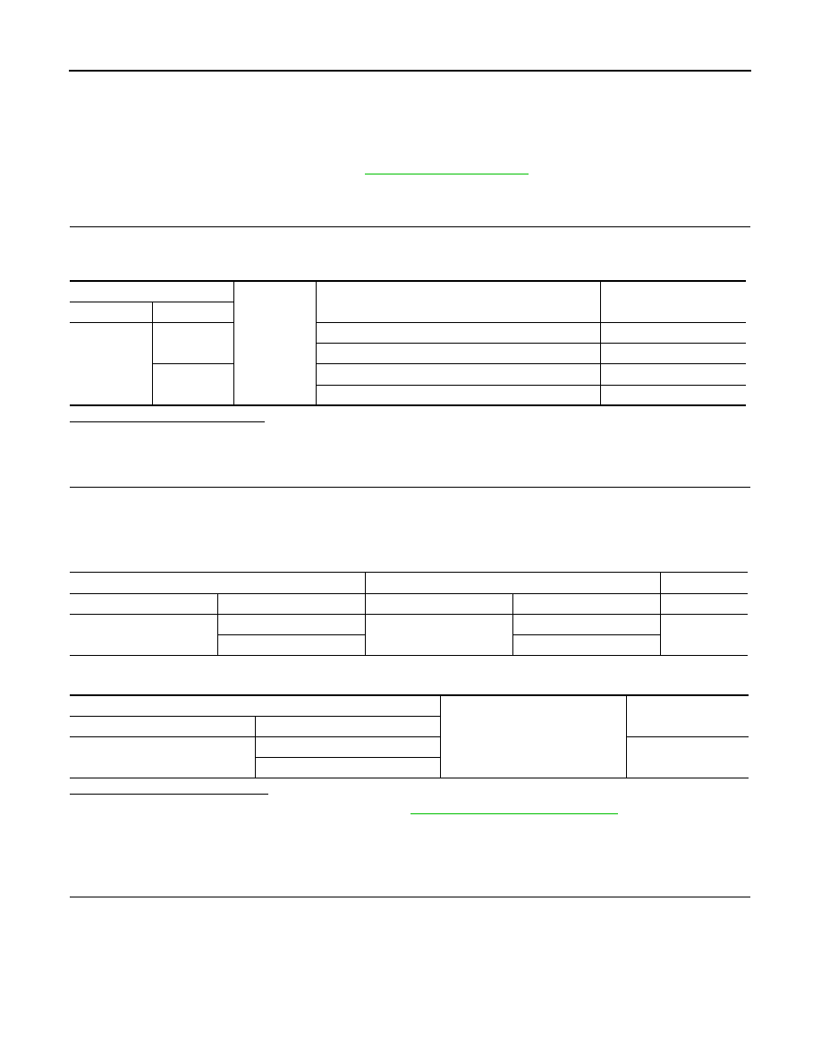
2. Check voltage between the following terminals of the illumination control switch.
Is the inspection result normal?
YES
>> Inspection End.
NO
>> GO TO 2.
2.
CHECK ILLUMINATION CONTROL SWITCH SIGNAL CIRCUIT
1. Turn ignition switch OFF.
2. Disconnect combination meter connector M24 and illumination control switch connector M66.
3. Check continuity between combination meter harness connector and illumination control switch harness
connector.
4. Check continuity between combination meter harness connector and ground.
Is the inspection result normal?
YES
>> Check illumination control switch. Refer to
MWI-56, "Component Inspection"
.
NO
>> Repair or replace harness or connector.
Component Inspection
INFOID:0000000009758281
1.
CHECK ILLUMINATION CONTROL SWITCH
1. Turn ignition switch OFF.
2. Disconnect illumination control switch connector.
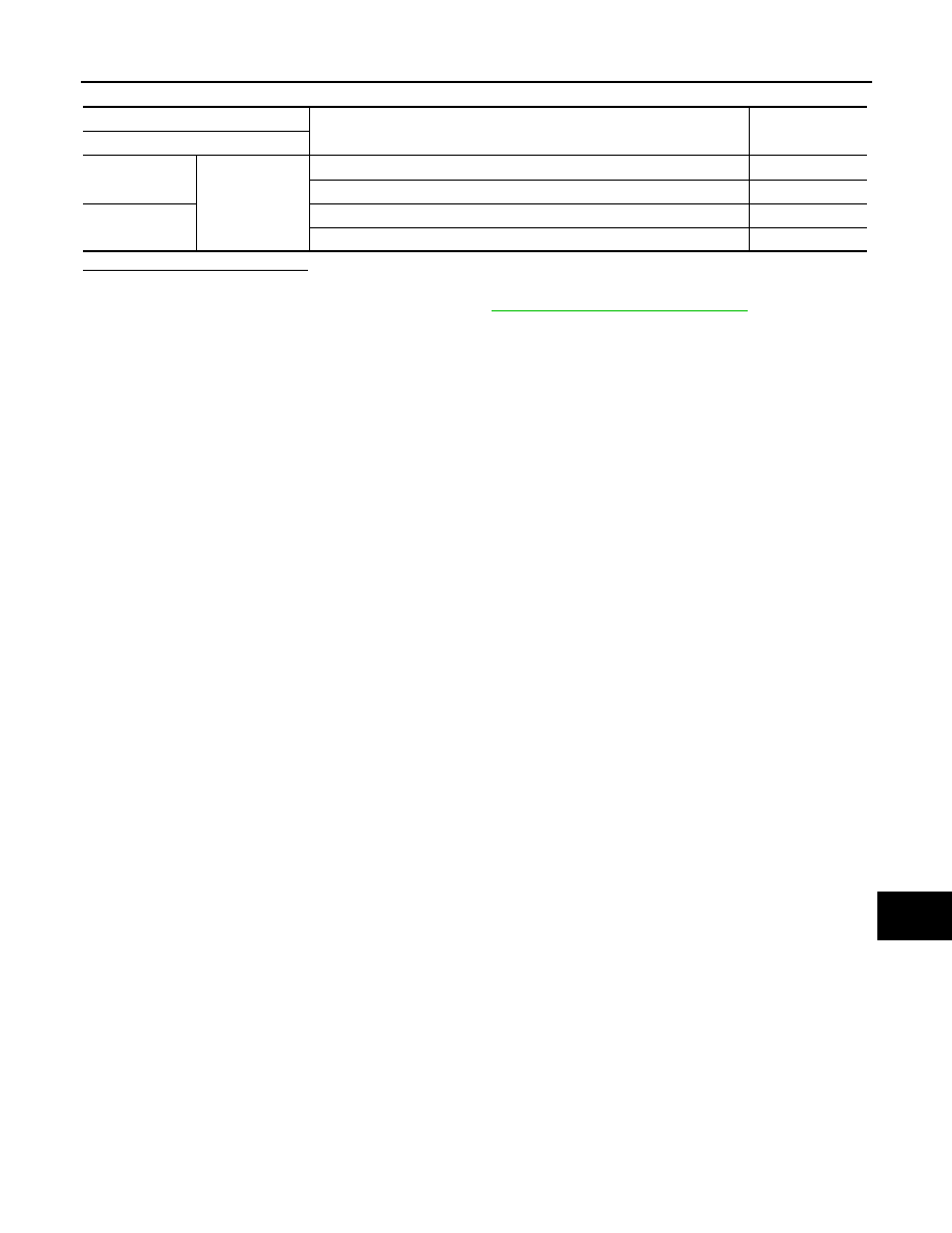
3. Check illumination control switch.
Illumination control switch
Ground
Condition
Voltage
(Approx.)
Connector
Terminals
M66
1
When illumination control switch (+) is pressed
0 V
Other than the above
5 V
2
When illumination control switch (
−) is pressed
0 V
Other than the above
5 V
Combination meter
Illumination control switch
Continuity
Connector
Terminal
Connector
Terminal
M24
33
M66
1
Yes
34
2
Combination meter
Ground
Continuity
Connector
Terminal
M24
33
No
34
MWI
ILLUMINATION CONTROL SWITCH SIGNAL CIRCUIT
MWI-57
< DTC/CIRCUIT DIAGNOSIS >
C
D
E
F
G
H
I
J
K
L
M
B
A
O
P
Is the inspection result normal?
YES
>> Inspection End.
NO
>> Replace illumination control switch. Refer to
MWI-80, "Removal and Installation"
Terminals
Condition
Continuity
Illumination control switch
1
4
When illumination control switch (+) is pressed
Yes
Other than the above
No
2
When illumination control switch (
−) is pressed
Yes
Other than the above
No
Нет комментариевНе стесняйтесь поделиться с нами вашим ценным мнением.
Текст