Nissan Sentra. Instruction — part 38
AV-144
< SYSTEM DESCRIPTION >
[DISPLAY AUDIO WITH BOSE]
DIAGNOSIS SYSTEM (AUDIO UNIT)
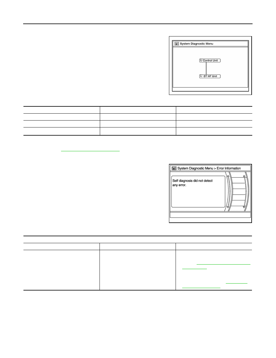
2. Self diagnosis screen is displayed. The bar graph visible in center of screen indicates progress of self
diagnosis.
3. Diagnosis results are displayed after the self diagnosis is com-
pleted. The unit names and the connection lines are color coded
according to the diagnostic results.
1: Control unit (audio unit) is displayed in red.
• Replace audio unit if Self Diagnosis did not run because control unit malfunction is indicated. The symptom is audio unit internal
error. Refer to
AV-203, "Removal and Installation"
.
• If multiple errors occur at the same time for a single unit, the screen switch colors are determined according to the following order
of priority: red > gray.
4. Comments of self diagnosis results can be viewed in the diagno-
sis result screen.
Audio Unit Self Diagnosis Results
AWNIA2832GB
Diagnosis results
Unit
Connection line
Normal
Green
Green
Connection malfunction
Gray
Yellow
Unit malfunction
1
Red
Green
JSNIA1870ZZ
Only Unit Part Is Displayed In Red
Screen switch
Description
Possible cause
Control unit
Malfunction is detected in audio unit power
supply and ground circuits.
• Audio unit power supply or ground cir-
cuits.
Refer to
.
• If no malfunction is detected in audio unit
power supply and ground circuits, re-
place audio unit. Refer to
.
AV
DIAGNOSIS SYSTEM (AUDIO UNIT)
AV-145
< SYSTEM DESCRIPTION >
[DISPLAY AUDIO WITH BOSE]
C
D
E
F
G
H
I
J
K
L
M
B
A
O
P
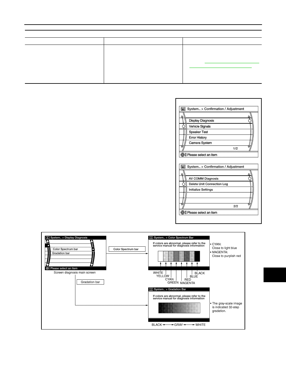
Audio Unit Confirmation/Adjustment
1. Select Confirmation/Adjustment.
2. Select each switch on the Confirmation/Adjustment screen to
display the relevant trouble diagnosis screen. Press the BACK
switch to return to the initial Confirmation/Adjustment screen.
Display Diagnosis
Vehicle Signals
A Connecting Cable Between Units Is Displayed In Yellow
Area with yellow connection lines
Description
Possible cause
Control unit
⇔ BT HF Unit
When one of the following is detected:
• malfunction is detected in Bluetooth
®
control unit power supply and ground cir-
cuits.
• malfunction is detected in AV communi-
cation circuits between audio unit and
Bluetooth
®
control unit.
• Bluetooth
®
control unit power supply or
ground circuits.
Refer to
TROL UNIT : Diagnosis Procedure"
• AV communication circuits between au-
dio unit and Bluetooth
®
control unit.
AWNIA2631GB
AWNIA2632GB
AV-146
< SYSTEM DESCRIPTION >
[DISPLAY AUDIO WITH BOSE]
DIAGNOSIS SYSTEM (AUDIO UNIT)
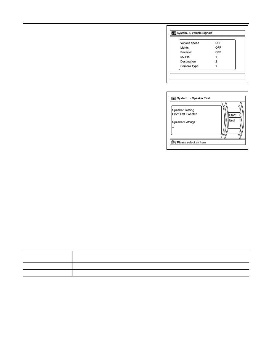
A comparison check can be made of each actual vehicle signal and
the signals recognized by the system.
Speaker Test
Select Speaker Test to display the Speaker Diagnosis screen. Press
Start to generate a test tone in a speaker. Press Start again to gener-
ate a test tone in the next speaker. Press End to stop the test tones.
Error History
The self diagnosis results are judged depending on whether any error occurs from when Self Diagnosis is
selected until the self diagnosis results are displayed.
However, the diagnosis results are judged normal if an error has occurred before the ignition switch is turned
ON and then no error has occurred until the self diagnosis start. Check the Error Record to detect any error
that may have occurred before the self diagnosis start because of this situation.
The frequency of occurrence is displayed in a count up manner. The actual count up method differs depending
on the error item.
Count up method A
• The counter is set to 40 if an error occurs. 1 is subtracted from the counter if the condition is normal at a next
ignition ON cycle.
• The counter lower limit is 1. The counter can be reset (no error record display) with the Delete log switch.
Count up method B
• The counter increases by 1 if an error occurs when ignition switch is ON. The counter will not decrease even
if the condition is normal at the next ignition ON cycle.
• The counter upper limit is 50. Any counts exceeding 50 are ignored. The counter can be reset (no error
record display) with the Delete log switch.
Error item
Some error items may be displayed simultaneously according to the cause. If some error items are displayed
simultaneously, the detection of the cause can be performed by the combination of display items
AWNIA2633GB
AWNIA2634GB
Display type of occurrence
frequency
Error history display item
Count up method A
AV communication line, control unit (AV)
Count up method B
Other than the above
AV
DIAGNOSIS SYSTEM (AUDIO UNIT)
AV-147
< SYSTEM DESCRIPTION >
[DISPLAY AUDIO WITH BOSE]
C
D
E
F
G
H
I
J
K
L
M
B
A
O
P
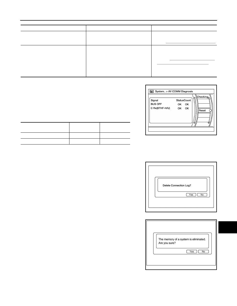
AV COMM Diagnosis
• Displays the communication status between audio unit (master
unit) and Bluetooth
®
control unit.
• The error counter displays OK if any malfunction was not detected
in the past and displays 0 if a malfunction is detected. It increases
by 1 if the condition is normal at the next ignition switch ON cycle.
The upper limit of the counter is 39.
• The error counter is erased if Reset is pressed.
NOTE:
“???” indicates UNKWN.
Delete Unit Connection Log
Deletes any unit connection records and error records from the
audio unit memory (clears the records of the unit that has been
removed).
Initialize Settings
Deletes data stored from the audio unit.
Error item
Description
Possible cause
CONTROL UNIT (AV)
AV communication circuit initial diagnosis
malfunction is detected.
Replace the audio unit if the malfunction
occurs constantly.
Refer to
AV-203, "Removal and Installation"
AV COMM CIRCUIT
When one of the following is detected:
• malfunction is detected in Bluetooth
®
control unit power supply and ground cir-
cuits.
• malfunction is detected in AV communi-
cation circuits between audio unit and
Bluetooth
®
control unit.
• Bluetooth
®
control unit power supply or
ground circuits.
Refer to
TROL UNIT : Diagnosis Procedure"
• AV communication circuits between au-
dio unit and Bluetooth
®
control unit.
Items
Status
(Current)
Counter
(Past)
BUS OFF
OK / ???
OK / 0 – 39
C Rx(BTHF-H/U)
OK / ???
OK / 0 – 39
AWNIA2833GB
AWNIA2637GB
JSNIA0155GB
Нет комментариевНе стесняйтесь поделиться с нами вашим ценным мнением.
Текст