Nissan Sentra. Instruction — part 45
AV-172
< BASIC INSPECTION >
[DISPLAY AUDIO WITH BOSE]
DIAGNOSIS AND REPAIR WORKFLOW
Is malfunctioning part detected?
YES
>> GO TO 4
NO
>> GO TO 2
4.
REPAIR OR REPLACE THE MALFUNCTIONING PART
1. Repair or replace the malfunctioning part.
2. Reconnect parts or connectors disconnected during Diagnostic Procedure.
>> GO TO 5
5.
FINAL CHECK
Refer to confirmed symptom in step 2, and make sure that the symptom is not detected.
Was the repair confirmed?
YES
>> Inspection End.
NO
>> GO TO 2
AV
POWER SUPPLY AND GROUND CIRCUIT
AV-173
< DTC/CIRCUIT DIAGNOSIS >
[DISPLAY AUDIO WITH BOSE]
C
D
E
F
G
H
I
J
K
L
M
B
A
O
P
DTC/CIRCUIT DIAGNOSIS
POWER SUPPLY AND GROUND CIRCUIT
AUDIO UNIT
AUDIO UNIT : Diagnosis Procedure
INFOID:0000000009758896
Regarding Wiring Diagram information, refer to
.
1.
CHECK FUSE
Check that the following fuses are not blown.
Are the fuses blown?
YES
>> Replace the blown fuse after repairing the affected circuit.
NO
>> GO TO 2.
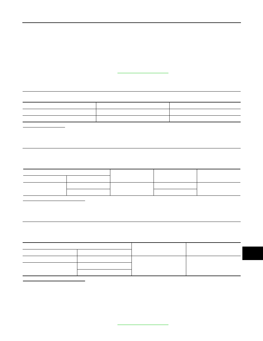
2.
CHECK POWER SUPPLY CIRCUIT
1. Turn ignition switch OFF.
2. Disconnect audio unit connector M94.
3. Check voltage between audio unit connector M94 and ground.
Is the inspection result normal?
YES
>> GO TO 3.
NO
>> Repair or replace harness or connectors.
3.
CHECK GROUND CIRCUIT
1. Turn ignition switch OFF.
2. Disconnect audio unit connector M95.
3. Check continuity between audio unit connectors and ground.
Is the inspection result normal?
YES
>> Inspection End.
NO
>> Repair or replace harness or connectors.
BOSE SPEAKER AMP
BOSE SPEAKER AMP : Diagnosis Procedure
INFOID:0000000009758897
Regarding Wiring Diagram information, refer to
.
Terminal No.
Signal name
Fuse No.
7
ACC power supply
18 (10A)
19
Battery power supply
26 (15A)
Audio unit
Ground
Condition
Voltage
(Approx.)
Connector
Terminal
M94
7
—
Ignition switch: ON
Battery voltage
19
Ignition switch: OFF
Audio unit
Ground
Continuity
Connector
Terminal
M94
20
—
Yes
M95
46
47

AV-174
< DTC/CIRCUIT DIAGNOSIS >
[DISPLAY AUDIO WITH BOSE]
POWER SUPPLY AND GROUND CIRCUIT
1.
CHECK FUSE
Check that the following fuses are not blown.
Are the fuses blown?
YES
>> Replace the blown fuse after repairing the affected circuit.
NO
>> GO TO 2.
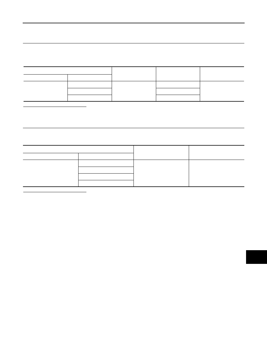
2.
CHECK POWER SUPPLY CIRCUIT
1. Turn ignition switch OFF.
2. Disconnect Bose speaker amp. connector B44.
3. Check voltage between Bose speaker amp. connector B44 and ground.
Is the inspection result normal?
YES
>> GO TO 3.
NO
>> Repair or replace harness or connectors.
3.
CHECK GROUND CIRCUIT
1. Turn ignition switch OFF.
2. Disconnect Bose speaker amp. connector B44.
3. Check continuity between Bose speaker amp. connector B44 and ground.
Is the inspection result normal?
YES
>> Inspection End.
NO
>> Repair or replace harness or connectors.
BLUETOOTH® CONTROL UNIT
BLUETOOTH® CONTROL UNIT : Diagnosis Procedure
INFOID:0000000009758898
Regarding Wiring Diagram information, refer to
.
1.
CHECK FUSE
Check that the following fuses are not blown.
Are the fuses blown?
Terminal No.
Signal name
Fuse No.
27
Battery power supply
23 (15A)
28
24 (15A)
Bose speaker amp.
Ground
Condition
Voltage
(Approx.)
Connector
Terminal
B44
27
—
Ignition switch: OFF
Battery voltage
28
Bose speaker amp.
Ground
Continuity
Connector
Terminal
B44
26
—
Yes
31
Terminal No.
Signal name
Fuse No.
1
Battery power supply
26 (15A)
2
ACC power supply
18 (10A)
3
Ignition signal
5 (10A)
AV
POWER SUPPLY AND GROUND CIRCUIT
AV-175
< DTC/CIRCUIT DIAGNOSIS >
[DISPLAY AUDIO WITH BOSE]
C
D
E
F
G
H
I
J
K
L
M
B
A
O
P
YES
>> Replace the blown fuse after repairing the affected circuit.
NO
>> GO TO 2.
2.
CHECK POWER SUPPLY CIRCUIT
1. Turn ignition switch OFF.
2. Disconnect Bluetooth
®
control unit connector M45.
3. Check voltage between Bluetooth
®
control unit connector M45 and ground.
Is the inspection result normal?
YES
>> GO TO 3.
NO
>> Repair or replace harness or connectors.
3.
CHECK GROUND CIRCUIT
1. Turn ignition switch OFF.
2. Check continuity between Bluetooth
®
control unit connector M45 and ground.
Is the inspection result normal?
YES
>> Inspection End.
NO
>> Repair or replace harness or connectors.
Bluetooth
®
control unit
Ground
Condition
Voltage
(Approx.)
Connector
Terminal
M45
1
—
Ignition switch: OFF
Battery voltage
2
Ignition switch: ACC
3
Ignition switch: ON
Bluetooth
®
control unit
Ground
Continuity
Connector
Terminal
M45
4
—
Yes
21
22
24
Нет комментариевНе стесняйтесь поделиться с нами вашим ценным мнением.
Текст