Nissan Sentra. Instruction — part 211
DIAGNOSIS SYSTEM (BCM) (WITHOUT INTELLIGENT KEY SYSTEM)
DEF-9
< SYSTEM DESCRIPTION >
C
D
E
F
G
H
I
J
K
M
A
B
DEF
N
O
P
DIAGNOSIS SYSTEM (BCM) (WITHOUT INTELLIGENT KEY SYSTEM)
COMMON ITEM
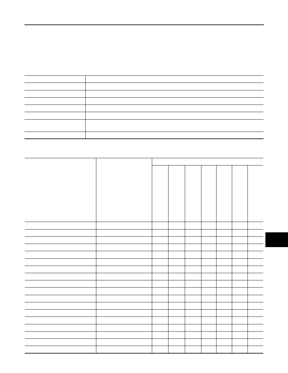
COMMON ITEM : CONSULT Function (BCM - COMMON ITEM)
INFOID:0000000010288766
APPLICATION ITEM
CONSULT performs the following functions via CAN communication with BCM.
SYSTEM APPLICATION
BCM can perform the following functions.
Direct Diagnostic Mode
Description
ECU identification
The BCM part number is displayed.
Self Diagnostic Result
The BCM self diagnostic results are displayed.
Data Monitor
The BCM input/output data is displayed in real time.
Active Test
The BCM activates outputs to test components.
Work support
The settings for BCM functions can be changed.
Configuration
• The vehicle specification can be read and saved.
• The vehicle specification can be written when replacing BCM.
CAN DIAG SUPPORT MNTR
The result of transmit/receive diagnosis of CAN communication is displayed.
System
Sub System
Direct Diagnostic Mode
ECU id
en
tif
ica
tion
Se
lf Di
ag
no
st
ic
Res
u
lt
Dat
a
M
on
ito
r
Acti
ve
T
est
W
o
rk
su
pp
ort
Co
nf
ig
ur
at
io
n
CAN DIAG SUP
P
OR
T MNTR
Door lock
DOOR LOCK
×
×
×
×
Rear window defogger
REAR DEFOGGER
×
×
Warning chime
BUZZER
×
×
Interior room lamp timer
INT LAMP
×
×
×
Remote keyless entry system
MULTI REMOTE ENT
×
×
×
Exterior lamp
HEAD LAMP
×
×
×
Wiper and washer
WIPER
×
×
×
Turn signal and hazard warning lamps FLASHER
×
×
Air conditioner
AIR CONDITIONER
×
Combination switch
COMB SW
×
BCM
BCM
×
×
×
×
×
Immobilizer
IMMU
×
×
×
Interior room lamp battery saver
BATTERY SAVER
×
×
×
Trunk open
TRUNK
×
RAP system
RETAINED PWR
×
×
Signal buffer system
SIGNAL BUFFER
×
TPMS
AIR PRESSURE MONITOR
×
×
×
×
Panic alarm system
PANIC ALARM
×

DEF-10
< SYSTEM DESCRIPTION >
DIAGNOSIS SYSTEM (BCM) (WITHOUT INTELLIGENT KEY SYSTEM)
REAR WINDOW DEFOGGER
REAR WINDOW DEFOGGER : CONSULT Function (BCM - REAR DEFOGGER)
INFOID:0000000010288767
DATA MONITOR
ACTIVE TEST
Monitor Item [Unit]
Description
IGN ON SW [On/Off]
Indicates condition of ignition switch ON position.
ACC ON SW [On/Off]
Indicates condition of ignition switch ACC position.
REAR DEF SW [On/Off]
Indicates condition of rear window defogger switch.
RR DEF TIME [On/Off]
Indicates condition of rear window defogger switch timer.
Test Item
Description
REAR DEFOGGER
This test is able to check rear window defogger operation [Off/On].

DIAGNOSIS SYSTEM (IPDM E/R) (WITH INTELLIGENT KEY SYSTEM)
DEF-11
< SYSTEM DESCRIPTION >
C
D
E
F
G
H
I
J
K
M
A
B
DEF
N
O
P
DIAGNOSIS SYSTEM (IPDM E/R) (WITH INTELLIGENT KEY SYSTEM)
Diagnosis Description
INFOID:0000000010288768
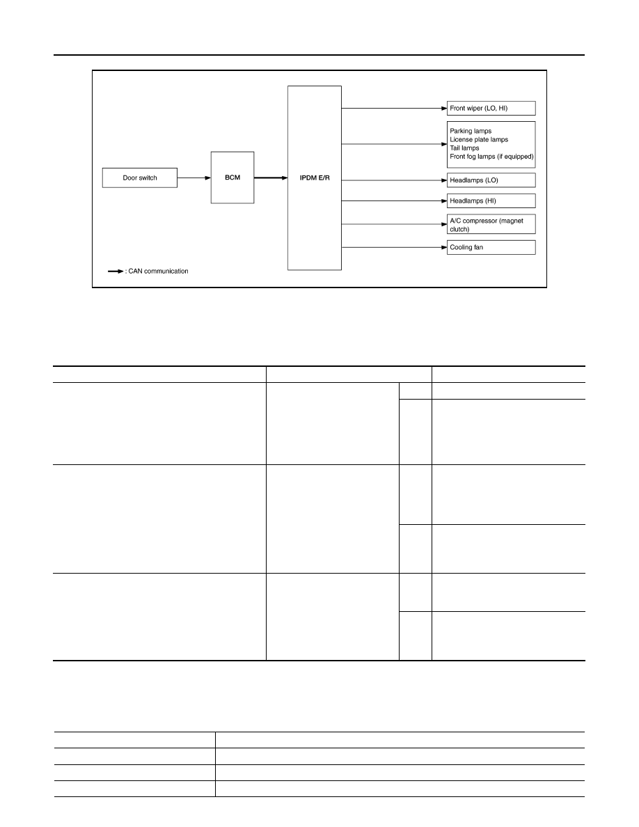
AUTO ACTIVE TEST
Description
In auto active test, the IPDM E/R sends a drive signal to the following systems to check their operation.
• Front wiper (LO, HI)
• Parking lamp
• License plate lamp
• Tail lamp
• Front fog lamp (if equipped)
• Headlamp (LO, HI)
• A/C compressor (magnet clutch)
• Cooling fan
Operation Procedure
NOTE:
Never perform auto active test in the following conditions.
• Passenger door is open
• CONSULT is connected
1. Close the hood and lift the wiper arms from the windshield. (Prevent windshield damage due to wiper
operation)
NOTE:
When auto active test is performed with hood opened, sprinkle water on windshield beforehand.
2. Turn the ignition switch OFF.
3. Turn the ignition switch ON, and within 20 seconds, press the driver door switch 10 times. Then turn the
ignition switch OFF.
4. Turn the ignition switch ON within 10 seconds. After that the horn sounds once and the auto active test
starts.
5. After a series of the following operations is repeated 3 times, auto active test is completed.
NOTE:
• When auto active test has to be cancelled halfway through test, turn the ignition switch OFF.
• When auto active test is not activated, door switch may be the cause. Check door switch. Refer to
.
Inspection in Auto Active Test
When auto active test is actuated, the following operation sequence is repeated 3 times.
Operation se-
quence
Inspection location
Operation
1
Front wiper
LO for 5 seconds
→ HI for 5 seconds
2
• Parking lamp
• License plate lamp
• Tail lamp
• Front fog lamp (if equipped)
10 seconds
3
Headlamp
LO for 10 seconds
→HI ON ⇔ OFF 5 times
4
A/C compressor (magnet clutch)
ON
⇔ OFF 5 times
5
Cooling fan
LO for 5 seconds
→ MID for 3 seconds → HI for 2 seconds
DEF-12
< SYSTEM DESCRIPTION >
DIAGNOSIS SYSTEM (IPDM E/R) (WITH INTELLIGENT KEY SYSTEM)
Concept of Auto Active Test
• IPDM E/R starts the auto active test with the door switch signals transmitted by BCM via CAN communica-
tion. Therefore, the CAN communication line between IPDM E/R and BCM is considered normal if the auto
active test starts successfully.
• The auto active test facilitates troubleshooting if any systems controlled by IPDM E/R cannot be operated.
Diagnosis Chart in Auto Active Test
CONSULT Function (IPDM E/R)
INFOID:0000000010288769
APPLICATION ITEM
CONSULT performs the following functions via CAN communication with IPDM E/R.
AWMIA1509GB
Symptom
Inspection contents
Possible cause
Any of the following components do not operate
• Parking lamp
• License plate lamp
• Tail lamp
• Front fog lamp (if equipped)
• Headlamp (HI, LO)
• Front wiper (HI, LO)
Perform auto active test.
Does the applicable system op-
erate?
YES
BCM signal input circuit
NO
• Lamp or motor
• Lamp or motor ground circuit
• Harness or connector between
IPDM E/R and applicable system
• IPDM E/R
A/C compressor does not operate
Perform auto active test.
Does the magnet clutch oper-
ate?
YES
• BCM signal input circuit
• CAN communication signal be-
tween BCM and ECM
• CAN communication signal be-
tween ECM and IPDM E/R
NO
• Magnet clutch
• Harness or connector between
IPDM E/R and magnet clutch
• IPDM E/R
Cooling fan does not operate
Perform auto active test.
Does the cooling fan operate?
YES
• ECM signal input circuit
• CAN communication signal be-
tween ECM and IPDM E/R
NO
• Cooling fan motor
• Harness or connector between
IPDM E/R and cooling fan motor
• IPDM E/R
Direct Diagnostic Mode
Description
Ecu Identification
The IPDM E/R part number is displayed.
Self Diagnostic Result
The IPDM E/R self diagnostic results are displayed.
Data Monitor
The IPDM E/R input/output data is displayed in real time.
Нет комментариевНе стесняйтесь поделиться с нами вашим ценным мнением.
Текст