Nissan Sentra. Instruction — part 387
EC-244
< DTC/CIRCUIT DIAGNOSIS >
[MRA8DE]
P014C, P014D, P015A, P015B A/F SENSOR 1
*: Check for linear voltage rise in response to engine being increased to about 4,000 rpm.
Without CONSULT
1. Repair or replace malfunctioning part.
2. Start engine and warm it up to normal operating temperature.
3. Check the voltage between ECM harness connector and ground.
*: Check for linear voltage rise in response to engine being increased to about 4,000 rpm.
Is the inspection result normal?
YES
>> INSPECTION END
NO
>> GO TO 4.
4.
CHECK MASS AIR FLOW SENSOR-3
With CONSULT
1. Turn ignition switch OFF.
2. Disconnect mass air flow sensor harness connector and reconnect it again.
3. Start engine and warm it up to normal operating temperature.
4. Connect CONSULT and select “DATA MONITOR” mode of “ENGINE”.
5. Select “MAS A/F SE-B1” and check indication.
*: Check for linear voltage rise in response to engine being increased to about 4,000 rpm.
Without CONSULT
1. Turn ignition switch OFF.
2. Disconnect mass air flow sensor harness connector and reconnect it again.
3. Start engine and warm it up to normal operating temperature.
4. Check the voltage between ECM harness connector and ground.
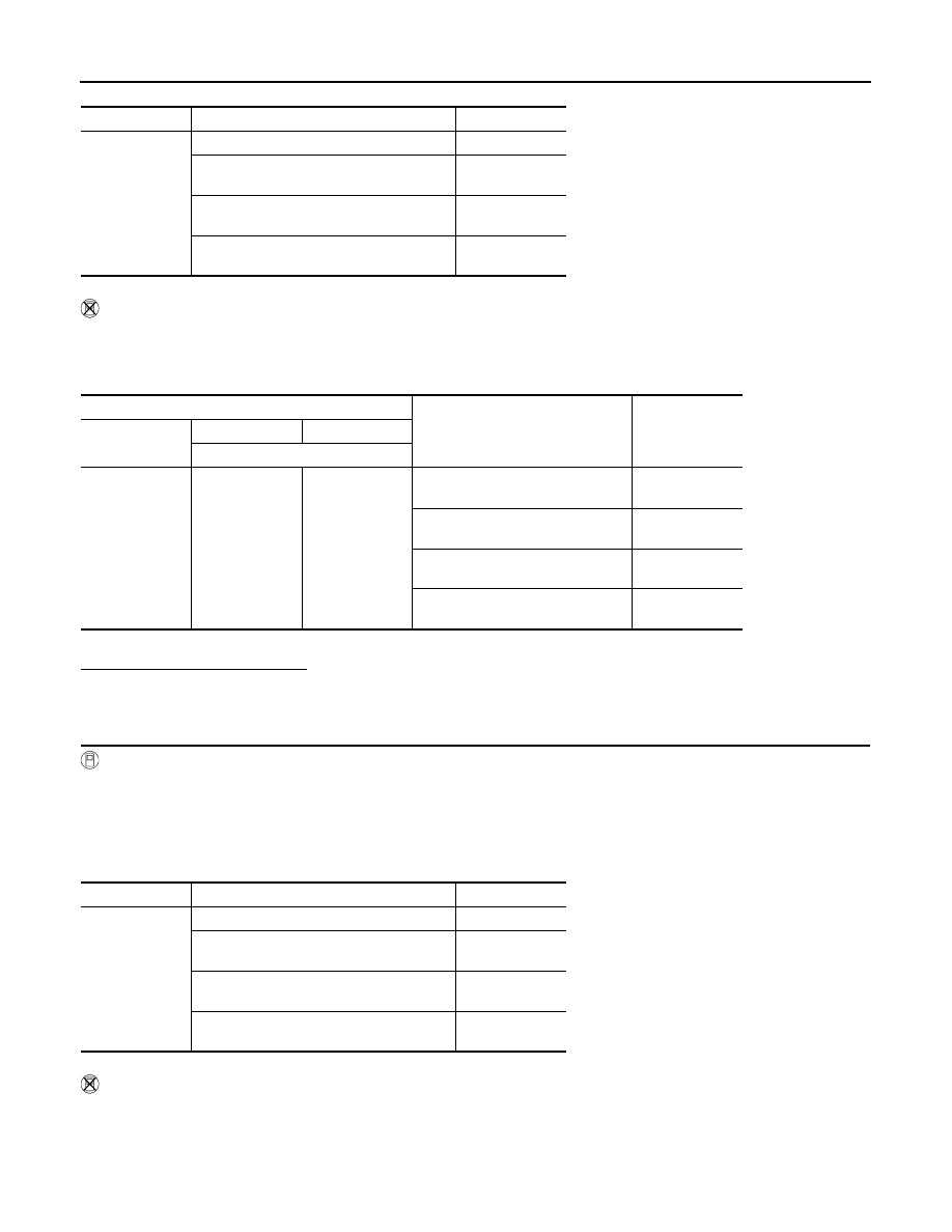
Monitor item
Condition
Value
MAS A/F SE-B1
Ignition switch ON (Engine stopped.)
Approx. 1.3 V
Idle (Engine is warmed-up to normal oper-
ating temperature.)
1.3 - 1.6 V
2,500 rpm (Engine is warmed-up to normal
operating temperature.)
1.8 - 2.2 V
Idle to about 4,000 rpm
1.3 - 1.6 V to Ap-
prox. 2.5 V*
ECM
Condition
Voltage
Connector
+
−
Terminal
F24
35
34
Ignition switch ON (Engine
stopped.)
Approx. 1.3 V
Idle (Engine is warmed-up to normal
operating temperature.)
1.3 - 1.6 V
2,500 rpm (Engine is warmed-up to
normal operating temperature.)
1.8 - 2.2 V
Idle to about 4,000 rpm
1.3 - 1.6 V to Ap-
prox. 2.5 V*
Monitor item
Condition
Value
MAS A/F SE-B1
Ignition switch ON (Engine stopped.)
Approx. 1.3 V
Idle (Engine is warmed-up to normal oper-
ating temperature.)
1.3 - 1.6 V
2,500 rpm (Engine is warmed-up to normal
operating temperature.)
1.8 - 2.2 V
Idle to about 4,000 rpm
1.3 - 1.6 V to Ap-
prox. 2.5 V*

P014C, P014D, P015A, P015B A/F SENSOR 1
EC-245
< DTC/CIRCUIT DIAGNOSIS >
[MRA8DE]
C
D
E
F
G
H
I
J
K
L
M
A
EC
N
P
O
*: Check for linear voltage rise in response to engine being increased to about 4,000 rpm.
Is the inspection result normal?
YES
>> INSPECTION END
NO
>> Clean or replace mass air flow sensor. Refer to
ECM
Condition
Voltage
Connector
+
−
Terminal
F24
35
34
Ignition switch ON (Engine
stopped.)
Approx. 1.3 V
Idle (Engine is warmed-up to normal
operating temperature.)
1.3 - 1.6 V
2,500 rpm (Engine is warmed-up to
normal operating temperature.)
1.8 - 2.2 V
Idle to about 4,000 rpm
1.3 - 1.6 V to Ap-
prox. 2.5 V*

EC-246
< DTC/CIRCUIT DIAGNOSIS >
[MRA8DE]
P0171 FUEL INJECTION SYSTEM FUNCTION
P0171 FUEL INJECTION SYSTEM FUNCTION
DTC Logic
INFOID:0000000009758498
DTC DETECTION LOGIC
With the Air/Fuel Mixture Ratio Self-Learning Control, the actual mixture ratio can be brought closely to the
theoretical mixture ratio based on the mixture ratio feedback signal from the A/F sensors 1. The ECM calcu-
lates the necessary compensation to correct the offset between the actual and the theoretical ratios.
In case the amount of the compensation value is extremely large (The actual mixture ratio is too lean.), the
ECM judges the condition as the fuel injection system malfunction and lights up the MIL (2 trip detection logic).
DTC CONFIRMATION PROCEDURE
1.
PRECONDITIONING
If DTC Confirmation Procedure has been previously conducted, always perform the following procedure
before conducting the next test.
1. Turn ignition switch OFF and wait at least 10 seconds.
2. Turn ignition switch ON.
3. Turn ignition switch OFF and wait at least 10 seconds.
>> GO TO 2.
2.
PERFORM DTC CONFIRMATION PROCEDURE-1
1. Clear the mixture ratio self-learning value. Refer to
.
2. Start engine.
Is it difficult to start engine?
YES
>> GO TO 3.
NO
>> GO TO 4.
3.
RESTART ENGINE
If it is difficult to start engine, the fuel injection system has a malfunction, too.
Crank engine while depressing accelerator pedal.
NOTE:
When depressing accelerator pedal three-fourths (3/4) or more, the control system does not start the
engine. Do not depress accelerator pedal too much.
Does engine start?
YES
>> Proceed to
.
NO
>> Check exhaust and intake air leak visually.
4.
PERFORM DTC CONFIRMATION PROCEDURE-2
1. Start engine and let it idle for at least 5 minutes.
2. Check 1st trip DTC.
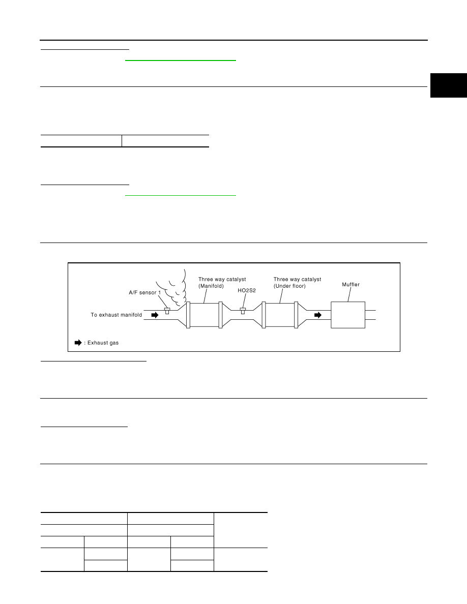
Sensor
Input signal to ECM
ECM function
Actuator
A/F sensor 1
Density of oxygen in exhaust gas
(Mixture ratio feedback signal)
Fuel injection control
Fuel injector
DTC No.
CONSULT screen terms
(Trouble diagnosis con-
tent)
DTC detecting condition
Possible cause
P0171
FUEL SYS-LEAN-B1
(System too lean bank 1)
• Fuel injection system does not operate properly.
• The amount of mixture ratio compensation is too
large. (The mixture ratio is too lean.)
• Intake air leaks
• A/F sensor 1
• Fuel injector
• Exhaust gas leaks
• Incorrect fuel pressure
• Lack of fuel
• Mass air flow sensor
• Incorrect PCV hose connection
P0171 FUEL INJECTION SYSTEM FUNCTION
EC-247
< DTC/CIRCUIT DIAGNOSIS >
[MRA8DE]
C
D
E
F
G
H
I
J
K
L
M
A
EC
N
P
O
Is 1st trip DTC detected?
YES
>> Proceed to
.
NO
>> GO TO 5.
5.
PERFORM DTC CONFIRMATION PROCEDURE-3
1. Turn ignition switch OFF and wait at least 10 seconds.
2. Start engine.
3. Maintain the following conditions for at least 10 consecutive minutes.
Hold the accelerator pedal as steady as possible.
CAUTION:
Always drive vehicle at a safe speed.
4. Check 1st trip DTC.
Is 1st trip DTC detected?
YES
>> Proceed to
.
NO
>> INSPECTION END
Diagnosis Procedure
INFOID:0000000009758499
1.
CHECK EXHAUST GAS LEAK
1. Start engine and run it at idle.
2. Listen for an exhaust gas leak before three way catalyst (manifold).
Is exhaust gas leak detected?
YES
>> Repair or replace error-detected parts.
NO
>> GO TO 2.
2.
CHECK FOR INTAKE AIR LEAK
1. Listen for an intake air leak after the mass air flow sensor.
2. Check PCV hose connection.
Intake air leak detected?
YES
>> Repair or replace error-detected parts.
NO
>> GO TO 3.
3.
CHECK A/F SENSOR 1 INPUT SIGNAL CIRCUIT
1. Turn ignition switch OFF.
2. Disconnect corresponding A/F sensor 1 harness connector.
3. Disconnect ECM harness connector.
4. Check the continuity between A/F sensor 1 harness connector and ECM harness connector.
*1: Except California
VHCL SPEED SE
50 - 120 km/h (31 - 75 MPH)
PBIB1216E
+
−
Continuity
A/F sensor 1
ECM
Connector
Terminal
Connector
Terminal
F12
*1
F42
*2
1
F24
41
Existed
2
45
Нет комментариевНе стесняйтесь поделиться с нами вашим ценным мнением.
Текст