Nissan Sentra. Instruction — part 348
EC-88
< ECU DIAGNOSIS INFORMATION >
[MRA8DE]
ECM
84
(W)
—
Sensor power supply
(Intake manifold runner
control valve position sen-
sor)
—
[Ignition switch: ON]
More than 4.98 V
86
(R)
128
(B/Y)
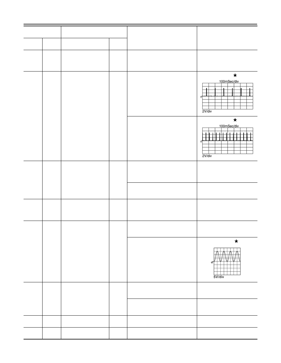
Ignition signal No. 1
Output
[Engine is running]
• Warm-up condition
• Idle speed
NOTE:
The pulse cycle changes depending
on rpm at idle
0 - 0.1 V
87
(LG)
Ignition signal No. 2
90
(P)
Ignition signal No. 3
[Engine is running]
• Warm-up condition
• Engine speed: 2,000 rpm
0 - 0.2 V
91
(SB)
Ignition signal No. 4
89
(GR)
128
(B/Y)
ECM relay
(Self shut-off)
Output
[Engine is running]
[Ignition switch: OFF]
• A few seconds after turning ignition
switch OFF
0 - 1.0 V
[Ignition switch: OFF]
• More than a few seconds after turn-
ing ignition switch OFF
Battery voltage
(11 - 14 V)
92
(LG)
—
Sensor ground
(Intake manifold runner
control valve position sen-
sor)
—
—
—
93
(LG)
128
(B/Y)
Intake valve timing control
solenoid valve
Output
[Engine is running]
• Warm-up condition
• Idle speed
0 V
[Engine is running]
• Warm-up condition
• When revving engine up to 2,000
rpm quickly
11 – 14 V
94
(G)
128
(B/Y)
Exhaust valve timing con-
trol solenoid valve
Output
[Engine is running]
• Warm-up condition
• Idle speed
0 V
[Engine is running]
• Warm-up condition
• Engine speed: 2,000 rpm
Battery voltage
(11 - 14 V)
97
(BR)
128
(GR)
EVAP canister vent con-
trol valve
Output
[Ignition switch: ON]
Battery voltage
(11 - 14 V)
99
(P)
—
CAN communication line
(CAN-L)
Input/
Output
—
—
Terminal No.
(Wire color)
Description
Condition
Value
(Approx.)
+
−
Signal name
Input/
Output
JPBIA4733ZZ
JPBIA4734ZZ
JMBIA1638GB

ECM
EC-89
< ECU DIAGNOSIS INFORMATION >
[MRA8DE]
C
D
E
F
G
H
I
J
K
L
M
A
EC
N
P
O
100
(L)
—
CAN communication line
(CAN-H)
Input/
Output
—
—
101
(G)
128
(B/Y)
Starter relay cut off signal
Input/
Output
[Ignition switch: ON]
0 V
[Engine is running]
• Warm-up condition
• Idle speed
Battery voltage
(11 - 14 V)
103
(P)
124
(Y)
Refrigerant pressure sen-
sor
Input
[Engine is running]
• Warm-up condition
• Both A/C switch and blower fan mo-
tor switch: ON (Compressor oper-
ates)
1.0 - 4.0 V
104
(L)
—
Sensor power supply
(Refrigerant pressure
sensor)
—
[Ignition switch: ON]
5.0 V
105
(V)
128
(B/Y)
Starter motor relay control
signal
Output
[Engine is running]
• Warm-up condition
• Idle speed
• Selector lever: D (CVT)
• Shift lever: 1st (M/T)
• Engine speed: Less than 1,500 rpm
NOTE:
To decrease engine speed, perform
the DTC confirmation procedure B in
P1650. Refer to
.
0 V
(While operating the starter mo-
tor)
[Engine is running]
• Warm-up condition
• Idle speed
Battery voltage
(11 - 14 V)
109
(O)
128
(B/Y)
Ignition switch
Input
[Ignition switch: OFF]
0 V
[Ignition switch: ON]
Battery voltage
(11 - 14 V)
110
(P)
111
(B)
ASCD steering switch
Input
[Ignition switch: ON]
• ASCD steering switch: OFF
4 V
[Ignition switch: ON]
• MAIN switch: Pressed
0 V
[Ignition switch: ON]
• CANCEL switch: Pressed
1 V
[Ignition switch: ON]
• ACCEL/RES switch: Pressed
3 V
[Ignition switch: ON]
• COAST/SET switch: Pressed
2 V
111
(B)
—
Sensor ground
(ASCD steering switch)
—
—
—
113
(G)
—
Sensor power supply
(EVAP control system
pressure sensor)
—
[Ignition switch: ON]
5.0 V
114
(P)
124
(SB)
EVAP control system
pressure sensor
Input
[Ignition switch: ON]
0.5 - 4.6 V
115
(SB)
128
(B/Y)
Stop lamp switch
Input
[Ignition switch: OFF]
• Brake pedal: Fully released
0 V
[Ignition switch: OFF]
• Brake pedal: Slightly depressed
Battery voltage
(11 - 14 V)
Terminal No.
(Wire color)
Description
Condition
Value
(Approx.)
+
−
Signal name
Input/
Output

EC-90
< ECU DIAGNOSIS INFORMATION >
[MRA8DE]
ECM
: Average voltage for pulse signal (Actual pulse signal can be confirmed by oscilloscope.)
*: Before measuring the terminal voltage, confirm that the battery is fully charged. Refer to
Fail Safe
INFOID:0000000009758391
NON DTC RELATED ITEM
116
(G)
128
(B/Y)
Brake pedal position
switch
Input
[Ignition switch: OFF]
• Brake pedal: Fully released
Battery voltage
(11 - 14 V)
[Ignition switch: OFF]
• Brake pedal: Slightly depressed
0 V
117
(BR)
128
(B/Y)
• PNP signal (CVT)
• Neutral switch (M/T)
Input
[Ignition switch: ON]
• Selector lever: P or N (CVT)
• Shifter lever: Neutral (M/T)
Battery voltage
(11 - 14 V)
[Ignition switch: ON]
• Except above
0 V
118
(O)
—
Sensor power supply
(Accelerator pedal posi-
tion sensor 2)
—
[Ignition switch: ON]
5.0 V
119
(W)
120
(Y)
Accelerator pedal posi-
tion sensor 2
Input
[Ignition switch: ON]
• Engine stopped
• Accelerator pedal: Fully released
0.3 – 0.6 V
[Ignition switch: ON]
• Engine stopped
• Accelerator pedal: Fully depressed
1.95 – 2.4 V
120
(Y)
—
Sensor ground
(Accelerator pedal posi-
tion sensor 2)
—
—
—
121
(G)
128
(B/Y)
Power supply for ECM
Input
[Ignition switch: ON]
Battery voltage
(11 - 14 V)
122
(V)
—
Sensor power supply
(Accelerator pedal posi-
tion sensor 1)
—
[Ignition switch: ON]
5.0 V
123
(B/Y)
—
ECM ground
—
—
—
124
(V)
—
Sensor ground
(EVAP control system
pressure sensor, refriger-
ant pressure sensor)
—
—
—
126
(R)
127
(GR)
Accelerator pedal posi-
tion sensor 1
Input
[Ignition switch: ON]
• Engine stopped
• Accelerator pedal: Fully released
0.6 – 0.9 V
[Ignition switch: ON]
• Engine stopped
• Accelerator pedal: Fully depressed
3.9 – 4.7 V
127
(GR)
—
Sensor ground
(Accelerator pedal posi-
tion sensor 1)
—
—
—
128
(B/Y)
—
ECM ground
—
—
—
Terminal No.
(Wire color)
Description
Condition
Value
(Approx.)
+
−
Signal name
Input/
Output

ECM
EC-91
< ECU DIAGNOSIS INFORMATION >
[MRA8DE]
C
D
E
F
G
H
I
J
K
L
M
A
EC
N
P
O
DTC RELATED ITEM
Description
When a DTC is detected, ECM executes a mode (in the Fail-safe mode) applicable to the DTC. The fail-safe
mode has the preset traveling control mode (accelerator angle variation and engine output limit) and device fix
mode.
Fail Safe Pattern
Fail Safe List
×:Applicable —: Not applicable
Detected
items
Engine operating condition
in fail-safe mode
Remarks
Reference page
Malfunction
indicator
circuit
Engine speed will not rise
more than 2,500 rpm due
to the fuel cut
When there is an open circuit on MIL circuit, the ECM cannot warn the
driver by lighting up MIL when there is malfunction on engine control
system.
Therefore, when electrical controlled throttle and part of ECM related
diagnoses are continuously detected as NG for 5 trips, ECM warns the
driver that engine control system malfunctions and MIL circuit is open
by means of operating fail safe function.
The fail safe function also operates when above diagnoses except MIL
circuit are detected and demands the driver to repair the malfunction.
EC-467, "Compo-
nent Function
Check"
Fail safe mode
Vehicle behavior
Traveling con-
trol mode
Accelerator an-
gle variation
control
ECM controls the accelerator pedal depression speed to make it slower than actual speed. This
causes a drop in accelerating performance and encourages the driver to repair malfunction.
NOTE:
ECM does not control the accelerator pedal releasing speed.
Engine output
control
ECM reduces the engine output, according to the rise in engine speed. This reduces the vehicle
speed to encourage the driver to repair malfunction.
Device fix mode
• This mode fixes the IVT control solenoid valve and the EVT control solenoid valve in the refer-
ence position.
• The intake manifold runner control valve motor is turned OFF (intake manifold runner control
valve opens).
Pattern
Fail safe mode
A
Traveling control mode
Accelerator angle variation control
B
Engine output control
C
Device fix mode
DTC
No.
Detected items
Vehicle behavior
Pattern
Others
A
B
C
P0075
Intake valve timing control
—
—
×
ECM activates the IVT intermediate lock control solenoid
valve to bring the cam sprocket into an intermediate lock con-
dition.
P0078
Exhaust valve timing control
—
—
×
—
P0101
P0102
P0103
Mass air flow sensor circuit
×
×
×
—
P0122
P0123
P0222
P0223
P2135
Throttle position sensor
—
—
—
The ECM controls the electric throttle control actuator in reg-
ulating the throttle opening in order for the idle position to be
within +10 degrees.
The ECM regulates the opening speed of the throttle valve to
be slower than the normal condition.
So, the acceleration will be poor.
Нет комментариевНе стесняйтесь поделиться с нами вашим ценным мнением.
Текст