Nissan Sentra. Instruction — part 664
PCS
DIAGNOSIS SYSTEM (IPDM E/R)
PCS-9
< SYSTEM DESCRIPTION >
[IPDM E/R (WITH I-KEY)]
C
D
E
F
G
H
I
J
K
L
B
A
O
P
N
DIAGNOSIS SYSTEM (IPDM E/R)
Diagnosis Description
INFOID:0000000009755811
AUTO ACTIVE TEST
Description
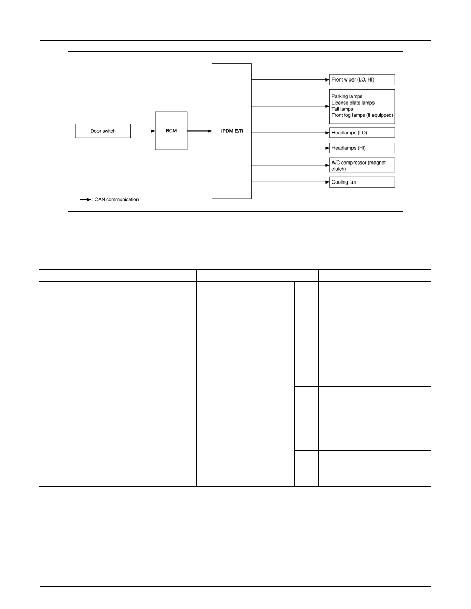
In auto active test, the IPDM E/R sends a drive signal to the following systems to check their operation.
• Front wiper (LO, HI)
• Parking lamp
• License plate lamp
• Tail lamp
• Front fog lamp (if equipped)
• Headlamp (LO, HI)
• A/C compressor (magnet clutch)
• Cooling fan
Operation Procedure
NOTE:
Never perform auto active test in the following conditions.
• Passenger door is open
• CONSULT is connected
1. Close the hood and lift the wiper arms from the windshield. (Prevent windshield damage due to wiper
operation)
NOTE:
When auto active test is performed with hood opened, sprinkle water on windshield beforehand.
2. Turn the ignition switch OFF.
3. Turn the ignition switch ON, and within 20 seconds, press the driver door switch 10 times. Then turn the
ignition switch OFF.
4. Turn the ignition switch ON within 10 seconds. After that the horn sounds once and the auto active test
starts.
5. After a series of the following operations is repeated 3 times, auto active test is completed.
NOTE:
• When auto active test has to be cancelled halfway through test, turn the ignition switch OFF.
• When auto active test is not activated, door switch may be the cause. Check door switch. Refer to
.
Inspection in Auto Active Test
When auto active test is actuated, the following operation sequence is repeated 3 times.
Operation se-
quence
Inspection location
Operation
1
Front wiper
LO for 5 seconds
→ HI for 5 seconds
2
• Parking lamp
• License plate lamp
• Tail lamp
• Front fog lamp (if equipped)
10 seconds
3
Headlamp
LO for 10 seconds
→HI ON ⇔ OFF 5 times
4
A/C compressor (magnet clutch)
ON
⇔ OFF 5 times
5
Cooling fan
LO for 5 seconds
→ MID for 3 seconds → HI for 2 seconds
PCS-10
< SYSTEM DESCRIPTION >
[IPDM E/R (WITH I-KEY)]
DIAGNOSIS SYSTEM (IPDM E/R)
Concept of Auto Active Test
• IPDM E/R starts the auto active test with the door switch signals transmitted by BCM via CAN communica-
tion. Therefore, the CAN communication line between IPDM E/R and BCM is considered normal if the auto
active test starts successfully.
• The auto active test facilitates troubleshooting if any systems controlled by IPDM E/R cannot be operated.
Diagnosis Chart in Auto Active Test
CONSULT Function (IPDM E/R)
INFOID:0000000009755812
APPLICATION ITEM
CONSULT performs the following functions via CAN communication with IPDM E/R.
AWMIA1509GB
Symptom
Inspection contents
Possible cause
Any of the following components do not operate
• Parking lamp
• License plate lamp
• Tail lamp
• Front fog lamp (if equipped)
• Headlamp (HI, LO)
• Front wiper (HI, LO)
Perform auto active test.
Does the applicable system op-
erate?
YES
BCM signal input circuit
NO
• Lamp or motor
• Lamp or motor ground circuit
• Harness or connector between
IPDM E/R and applicable system
• IPDM E/R
A/C compressor does not operate
Perform auto active test.
Does the magnet clutch oper-
ate?
YES
• BCM signal input circuit
• CAN communication signal be-
tween BCM and ECM
• CAN communication signal be-
tween ECM and IPDM E/R
NO
• Magnet clutch
• Harness or connector between
IPDM E/R and magnet clutch
• IPDM E/R
Cooling fan does not operate
Perform auto active test.
Does the cooling fan operate?
YES
• ECM signal input circuit
• CAN communication signal be-
tween ECM and IPDM E/R
NO
• Cooling fan motor
• Harness or connector between
IPDM E/R and cooling fan motor
• IPDM E/R
Direct Diagnostic Mode
Description
Ecu Identification
The IPDM E/R part number is displayed.
Self Diagnostic Result
The IPDM E/R self diagnostic results are displayed.
Data Monitor
The IPDM E/R input/output data is displayed in real time.

PCS
DIAGNOSIS SYSTEM (IPDM E/R)
PCS-11
< SYSTEM DESCRIPTION >
[IPDM E/R (WITH I-KEY)]
C
D
E
F
G
H
I
J
K
L
B
A
O
P
N
ECU IDENTIFICATION
The IPDM E/R part number is displayed.
SELF DIAGNOSTIC RESULT
DATA MONITOR
ACTIVE TEST
Active Test
The IPDM E/R activates outputs to test components.
CAN Diag Support Mntr
The result of transmit/receive diagnosis of CAN communication is displayed.
Direct Diagnostic Mode
Description
Monitor Item [Unit]
Main
Signals
Description
MOTOR FAN REQ [%]
×
Indicates cooling fan speed signal received from ECM on CAN communication
line
AC COMP REQ [On/Off]
×
Indicates A/C compressor request signal received from ECM on CAN commu-
nication line
TAIL&CLR REQ [On/Off]
×
Indicates position light request signal received from BCM on CAN communica-
tion line
HL LO REQ [On/Off]
×
Indicates low beam request signal received from BCM on CAN communication
line
HL HI REQ [On/Off]
×
Indicates high beam request signal received from BCM on CAN communication
line
FR FOG REQ [On/Off]
×
Indicates front fog light request signal received from BCM on CAN communica-
tion line
FR WIP REQ [Stop/1LOW/Low/Hi]
×
Indicates front wiper request signal received from BCM on CAN communication
line
WIP AUTO STOP [STOP P/ACT P]
×
Indicates condition of front wiper auto stop signal
WIP PROT [Off/BLOCK]
×
Indicates condition of front wiper fail-safe operation
IGN RLY1 -REQ [On/Off]
Indicates ignition switch ON signal received from BCM on CAN communication
line
IGN RLY [On/Off]
×
Indicates condition of ignition relay
PUSH SW [On/Off]
Indicates condition of push-button ignition switch
INTER/NP SW [On/Off]
Indicates condition of CVT shift position
ST RLY CONT [On/Off]
Indicates starter relay status signal received from BCM on CAN communication
line
IHBT RLY -REQ [On/Off]
Indicates starter control relay signal received from BCM on CAN communication
line
ST/INHI RLY [Off/ ST /INHI]
Indicates condition of starter relay and starter control relay
DETENT SW [On/Off]
Indicates condition of CVT shift selector (park position switch)
DTRL REQ [Off]
Indicates daytime light request signal received from BCM on CAN communica-
tion line
THFT HRN REQ [On/Off]
Indicates theft warning horn request signal received from BCM on CAN commu-
nication line
HORN CHIRP [On/Off]
Indicates horn reminder signal received from BCM on CAN communication line
Test item
Description
HORN
This test is able to check horn operation [On].
REAR DEFOGGER
This test is able to check rear window defogger operation [On/Off].
FRONT WIPER
This test is able to check wiper motor operation [Hi/Lo/Off].

PCS-12
< SYSTEM DESCRIPTION >
[IPDM E/R (WITH I-KEY)]
DIAGNOSIS SYSTEM (IPDM E/R)
CAN DIAG SUPPORT MNTR
LAN-13, "CAN Diagnostic Support Monitor"
.
MOTOR FAN
This test is able to check cooling fan operation [4/3/2/1].
EXTERNAL LAMPS
This test is able to check external lamp operation [Fog/Hi/Lo/TAIL/Off].
Test item
Description
Нет комментариевНе стесняйтесь поделиться с нами вашим ценным мнением.
Текст