Nissan Sentra. Instruction — part 848
TM-28
< UNIT REMOVAL AND INSTALLATION >
[6MT: RS6F94R]
TRANSAXLE ASSEMBLY
UNIT REMOVAL AND INSTALLATION
TRANSAXLE ASSEMBLY
Exploded View
INFOID:0000000009759284
Removal and Installation
INFOID:0000000009759285
WARNING:
Do not remove the radiator cap when the engine is hot. Serious burns could occur from high pressure
coolant escaping from the radiator. Wrap a thick cloth around the cap. Slowly turn it a quarter turn to
allow built-up pressure to escape. Carefully remove the cap by turning it all the way.
CAUTION:
Do not reuse CSC (Concentric Slave Cylinder). The CSC slides back to the original position every time
the transaxle assembly is removed. This action may allow dust or contaminants to gather on the slid-
ing parts and damage a seal of CSC causing clutch fluid leakage.
NOTE:
When removing components such as hoses, tubes/lines, etc., cap or plug openings to prevent fluid from spill-
ing.
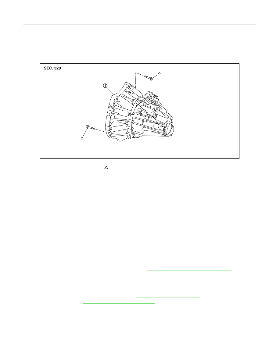
REMOVAL
1. Remove the engine and transaxle assembly. Refer to
EM-82, "M/T : Removal and Installation"
.
2. Disconnect the reverse lamp switch harness connector.
3. Remove the bolts that fasten the transaxle assembly and engine assembly.
4. Remove transaxle assembly from the engine assembly.
5. Remove engine mounting bracket (LH). Refer to
.
6. Remove CSC. Refer to
CL-16, "Removal and Installation"
.
INSTALLATION
Installation is in the reverse order of removal.
CAUTION:
• When replacing an engine or transaxle you must make sure any dowels are installed correctly during
re-assembly
• The transaxle assembly must not interfere with the wire harnesses and clutch tube.
1.
Transaxle assembly
Refer to INSTALLATION
JPDIC0137ZZ
TRANSAXLE ASSEMBLY
TM-29
< UNIT REMOVAL AND INSTALLATION >
[6MT: RS6F94R]
C
E
F
G
H
I
J
K
L
M
A
B
TM
N
O
P
• Improper alignment caused by missing dowels may cause vibration, oil leaks or breakage of drive
train components.
• When installing transaxle assembly, do not bring input shaft into contact with clutch cover.
• Tapping work for tapping bolts is not applied to new transaxle case. Do not perform tapping by other
than screwing tapping bolts because tapping is formed by screwing tapping bolts into transaxle
case.
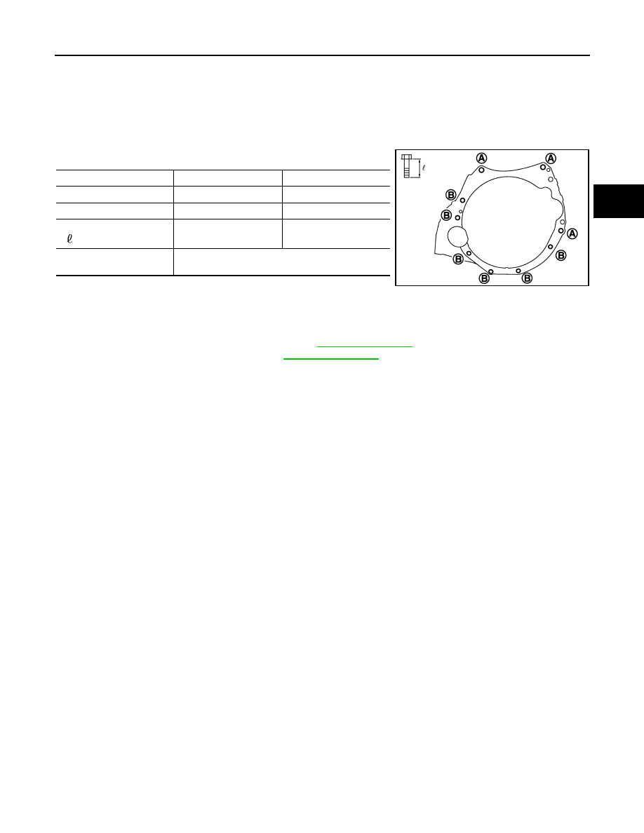
Tighten transaxle assembly mounting bolts to the specified torque. As shown viewing from
the engine.
Inspection
INFOID:0000000009759286
INSPECTION AFTER INSTALLATION
• Check the operation of the control linkage. Refer to
.
• Check the oil level and for oil leaks. Refer to
.
Bolt symbol
(A)
(B)
Insertion direction
Transaxle to engine
Engine to transaxle
Quantity
3
6
Bolt length
“ ” mm (in)
60 (2.36)
50 (1.97)
Tightening torque
N·m (kg-m, ft-lb)
62.0 (6.3, 46)
JPDIC0837ZZ
TM-30
< UNIT DISASSEMBLY AND ASSEMBLY >
[6MT: RS6F94R]
TRANSAXLE ASSEMBLY
UNIT DISASSEMBLY AND ASSEMBLY
TRANSAXLE ASSEMBLY
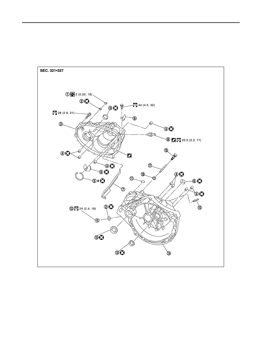
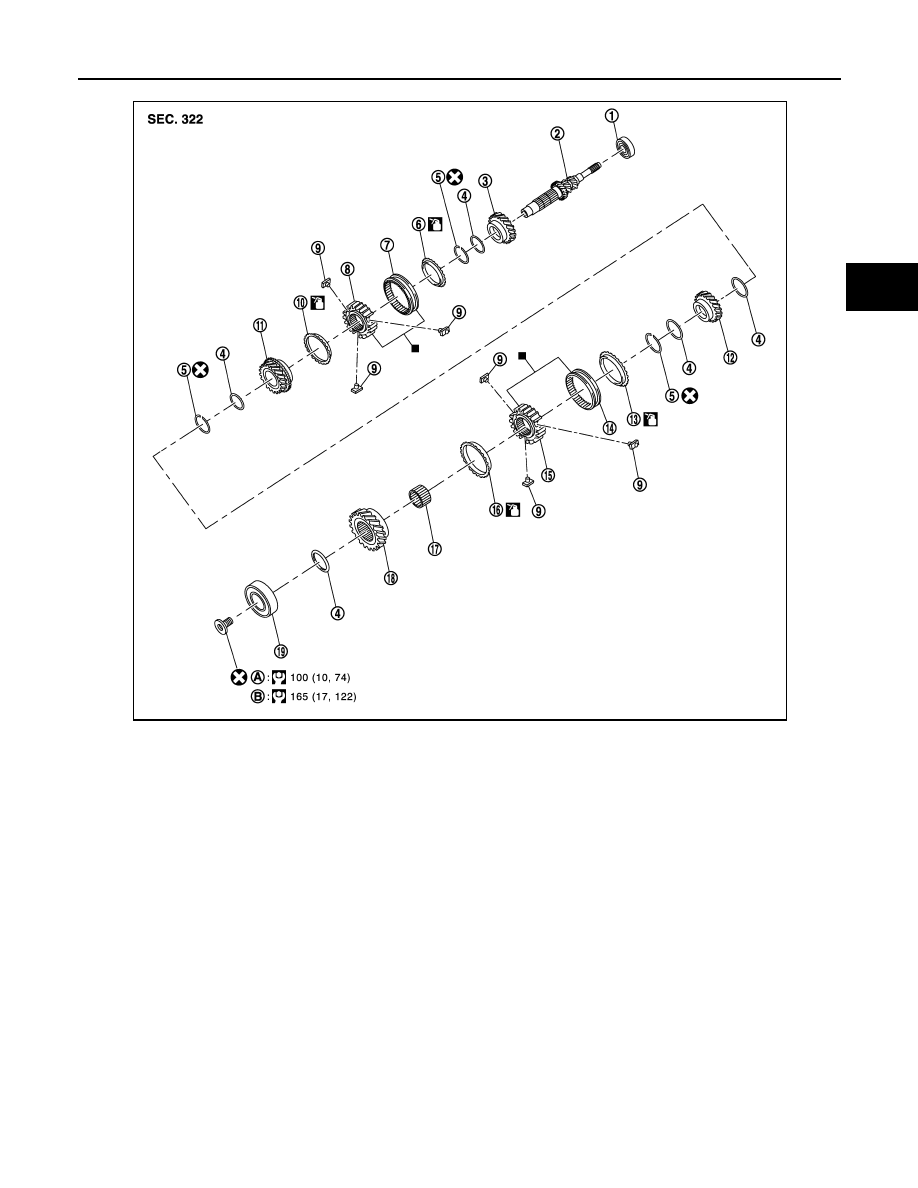
Exploded View
INFOID:0000000009759287
CASE AND HOUSING
SHAFT AND GEAR
1.
Filler plug
2.
Gasket
3.
Transaxle case
4.
Bushing
5.
Snap ring
6.
Oil channel
7.
Oil gutter
8.
Position switch
9.
Bracket
10. Differential side oil seal
11.
Magnet
12. Drain plug
13. Input shaft oil seal
14. Clutch housing
15. 2 way connector
16. Plug
17. Pinion shaft
18. Pinion gear
JPDIC0437GB
TRANSAXLE ASSEMBLY
TM-31
< UNIT DISASSEMBLY AND ASSEMBLY >
[6MT: RS6F94R]
C
E
F
G
H
I
J
K
L
M
A
B
TM
N
O
P
1.
Input shaft front bearing
2.
Input shaft
3.
3rd input gear
4.
Spacer
5.
Snap ring
6.
3rd baulk ring
7.
3rd-4th coupling sleeve
8.
3rd-4th synchronizer hub
9.
Insert key
10. 4th baulk ring
11.
4th input gear
12. 5th input gear
13. 5th baulk ring
14. 5th-6th coupling sleeve
15. 5th-6th synchronizer hub
16. 6th baulk ring
17. Needle bearing
18. 6th input gear
19. Input shaft rear bearing
A.
First step
B.
Final step
JPDIC0407GB
Нет комментариевНе стесняйтесь поделиться с нами вашим ценным мнением.
Текст