Nissan Sentra. Instruction — part 28
AV-104
< DTC/CIRCUIT DIAGNOSIS >
[DISPLAY AUDIO WITHOUT BOSE]
FRONT DOOR SPEAKER
Is the inspection result normal?
YES
>> Replace front door speaker. Refer to
AV-124, "Removal and Installation"
NO
>> Replace audio unit. Refer to
AV-122, "Removal and Installation"
.
2
3
Audio signal output
11
12
SKIB3609E

AV
FRONT TWEETER
AV-105
< DTC/CIRCUIT DIAGNOSIS >
[DISPLAY AUDIO WITHOUT BOSE]
C
D
E
F
G
H
I
J
K
L
M
B
A
O
P
FRONT TWEETER
Diagnosis Procedure
INFOID:0000000009758854
Regarding Wiring Diagram information, refer to
1.
CONNECTOR CHECK
Check the audio unit and speaker connectors for the following:
• Proper connection
• Damage
• Disconnected or loose terminals
Is the inspection result normal?
YES
>> GO TO 2
NO
>> Repair the terminals or connectors.
2.
CHECK FRONT TWEETER SIGNAL CIRCUIT CONTINUITY
1. Disconnect audio unit connector M92 and suspect front tweeter connector.
2. Check continuity between audio unit connector M92 and suspect front tweeter connector.
3. Check continuity between audio unit connector M92 and ground.
Is the inspection result normal?
YES
>> GO TO 3
NO
>> Repair or replace harness or connectors.
3.
CHECK FRONT TWEETER SIGNAL
1. Connect audio unit connector M92 and suspect front tweeter connector.
2. Turn ignition switch to ACC.
3. Push audio unit POWER switch.
4. Check signal between the terminals of audio unit connector M92.
Audio unit
Front tweeter
Continuity
Connector
Terminal
Connector
Terminal
M92
2
M46 (LH)
1
Yes
3
2
11
M47 (RH)
1
12
2
Audio unit
Ground
Continuity
Connector
Terminal
M92
2
—
No
3
11
12
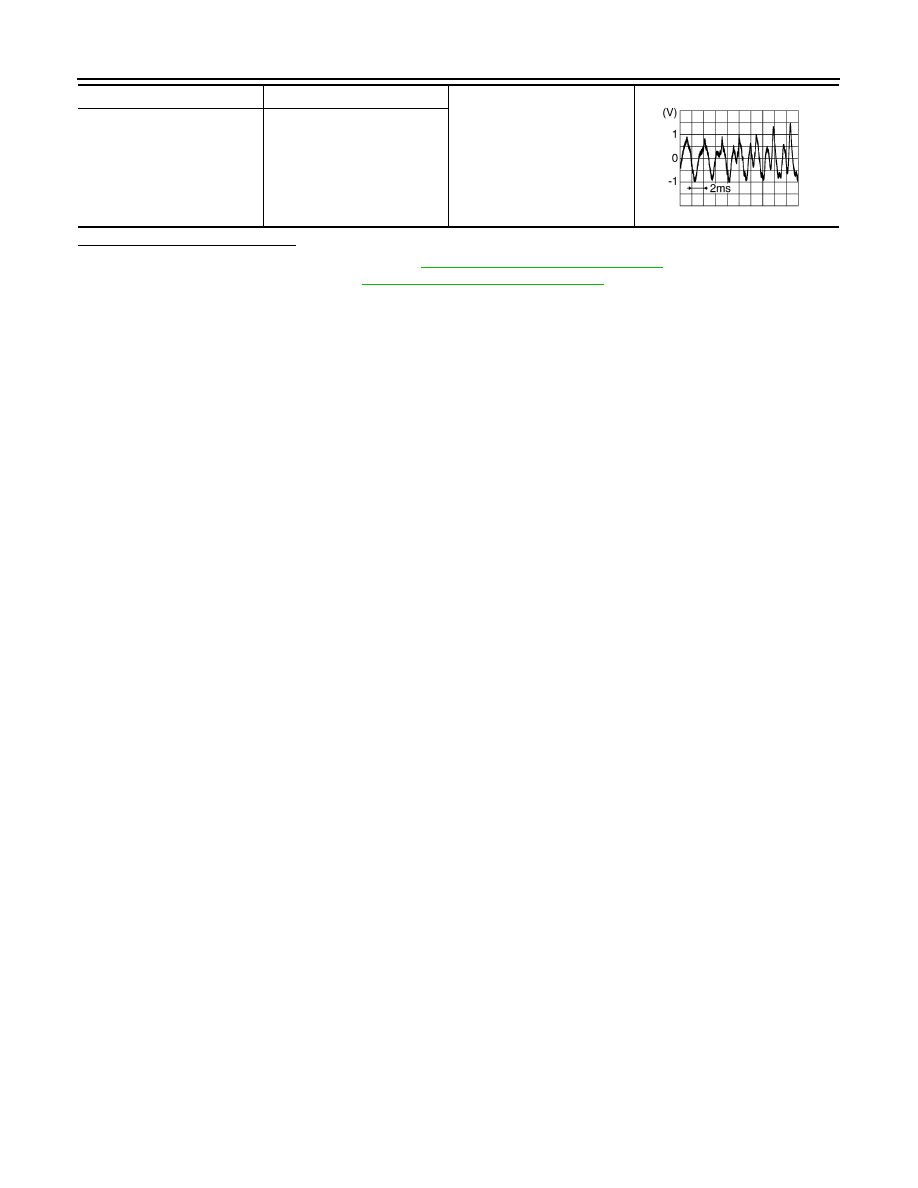
Audio unit connector M92
Condition
Reference value
(+)
(
−)
Terminal
Terminal

AV-106
< DTC/CIRCUIT DIAGNOSIS >
[DISPLAY AUDIO WITHOUT BOSE]
FRONT TWEETER
Is the inspection result normal?
YES
>> Replace front tweeter. Refer to
AV-123, "Removal and Installation"
NO
>> Replace audio unit. Refer to
AV-122, "Removal and Installation"
.
2
3
Audio signal output
11
12
SKIB3609E
AV
REAR SPEAKER
AV-107
< DTC/CIRCUIT DIAGNOSIS >
[DISPLAY AUDIO WITHOUT BOSE]
C
D
E
F
G
H
I
J
K
L
M
B
A
O
P
REAR SPEAKER
Diagnosis Procedure
INFOID:0000000009758855
Regarding Wiring Diagram information, refer to
1.
CONNECTOR CHECK
Check the audio unit and speaker connectors for the following:
• Proper connection
• Damage
• Disconnected or loose terminals
Is the inspection result normal?
YES
>> GO TO 2
NO
>> Repair the terminals or connectors.
2.
CHECK REAR SPEAKER SIGNAL CIRCUIT CONTINUITY
1. Disconnect audio unit connector M92 and suspect rear speaker connector.
2. Check continuity between audio unit connector M92 and suspect rear speaker connector.
3. Check continuity between audio unit connector M92 and ground.
Is the inspection result normal?
YES
>> GO TO 3
NO
>> Repair or replace harness or connectors.
3.
CHECK REAR SPEAKER SIGNAL
1. Connect audio unit connector M92 and suspect rear speaker connector.
2. Turn ignition switch to ACC.
3. Push audio unit POWER switch.
4. Check signal between the terminals of audio unit connector M92.
Audio unit
Rear speaker
Continuity
Connector
Terminal
Connector
Terminal
M92
4
B40 (LH)
1
Yes
5
2
13
B38 (RH)
1
14
2
Audio unit
Ground
Continuity
Connector
Terminal
M92
4
—
No
5
13
14
Audio unit connector M92
Condition
Reference value
(+)
(
−)
Terminal
Terminal
Нет комментариевНе стесняйтесь поделиться с нами вашим ценным мнением.
Текст