Nissan Sentra. Instruction — part 180
WHEEL SENSOR
BRC-107
< REMOVAL AND INSTALLATION >
[VDC/TCS/ABS]
C
D
E
G
H
I
J
K
L
M
A
B
BRC
N
O
P
Installation is in the reverse order of removal.
CAUTION:
• During installation, make sure there is no foreign material such as iron chips on and in the mounting
hole of the wheel sensor. Make sure no foreign material has been caught in the sensor rotor. Remove
and foreign material and clean the mount.
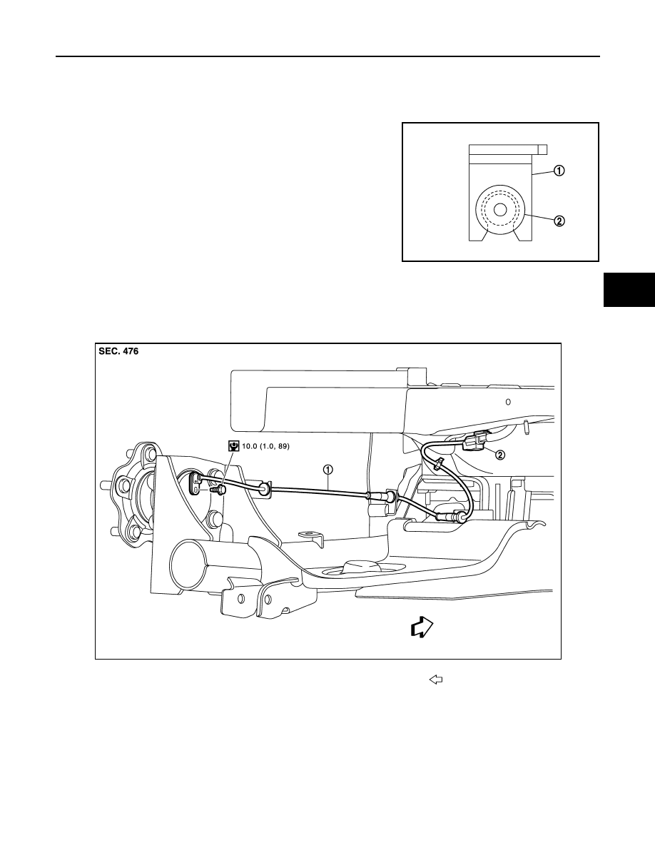
• Do not twist front wheel sensor harness when installing front
wheel sensor. Check that grommet (2) is fully inserted to
bracket (1). Check that front wheel sensor harness is not
twisted after installation.
REAR WHEEL SENSOR
REAR WHEEL SENSOR : Exploded View
INFOID:0000000009757901
REAR WHEEL SENSOR : Removal and Installation
INFOID:0000000009757902
CAUTION:
• Be careful not to damage wheel sensor edge and sensor rotor teeth.
• When removing the front or rear wheel hub, first remove the wheel sensor from the wheel hub. Fail-
ure to do so may result in damage to the wheel sensor wires, making the sensor inoperative.
• Pull out the wheel sensor, being careful to turn it as little as possible. Do not pull on the wheel sen-
sor harness.
JPFIC0209ZZ
1.
Rear wheel sensor
2.
Rear wheel sensor harness connector
Front
JPFIC0192GB
BRC-108
< REMOVAL AND INSTALLATION >
[VDC/TCS/ABS]
WHEEL SENSOR
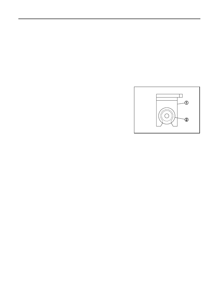
• Before installation, check if foreign objects such as iron fragments are adhered to the pick-up part of
the sensor or to the inside of the hole in the wheel hub for the wheel sensor, or if a foreign object is
caught in the surface of the mating surface for the sensor rotor. Clean as necessary and then install
the wheel sensor.
REMOVAL
1. Remove rear wheel sensor harness connector.
2. Remove rear wheel sensor bolt.
3. Remove rear wheel sensor harness from the brackets.
INSTALLATION
Installation is in the reverse order of removal.
CAUTION:
• During installation, make sure there is no foreign material such as iron chips on and in the mounting
hole of the wheel sensor. Make sure no foreign material has been caught in the sensor rotor. Remove
and foreign material and clean the mount.
• Do not twist front wheel sensor harness when installing front
wheel sensor. Check that grommet (2) is fully inserted to
bracket (1). Check that front wheel sensor harness is not
twisted after installation.
JPFIC0209ZZ
SENSOR ROTOR
BRC-109
< REMOVAL AND INSTALLATION >
[VDC/TCS/ABS]
C
D
E
G
H
I
J
K
L
M
A
B
BRC
N
O
P
SENSOR ROTOR
FRONT SENSOR ROTOR
FRONT SENSOR ROTOR : Removal and Installation
INFOID:0000000009757903
The front wheel sensor rotor is an integral part of the wheel hub and bearing assembly and cannot be disas-
FAX-8, "Removal and Installation"
REAR SENSOR ROTOR
REAR SENSOR ROTOR : Removal and Installation
INFOID:0000000009757904
The rear wheel sensor rotor is an integral part of the wheel hub and bearing assembly and cannot be disas-
sembled. Refer to
RAX-6, "Removal and Installation - Drum brake"
(disc brake).
BRC-110
< REMOVAL AND INSTALLATION >
[VDC/TCS/ABS]
ABS ACTUATOR AND ELECTRIC UNIT (CONTROL UNIT)
ABS ACTUATOR AND ELECTRIC UNIT (CONTROL UNIT)
Exploded View
INFOID:0000000009757905
Removal and Installation
INFOID:0000000009757906
REMOVAL
1. Disconnect battery negative terminal. Refer to
2. Drain brake fluid. Refer to
3. Remove the cowl top. Refer to
EXT-26, "Removal and Installation"
.
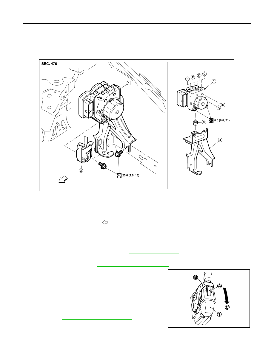
4. Disconnect ABS actuator and electric unit (control unit) harness
connector (1), follow the procedure described below.
a. Push the pawl (A).
b. Move the lever (B) in the direction (C) until locked.
c.
Disconnect ABS actuator and electric unit (control unit) harness
connector.
5. Loosen flare nut of brake tube using a flare nut wrench, and then
remove brake tube from ABS actuator and electric unit (control
unit). Refer to
BR-25, "FRONT : Exploded View"
6. Remove ABS actuator and electric unit (control unit) and
bracket.
7. Remove bracket and bushing from ABS actuator and electric unit (control unit).
1.
ABS actuator and electric unit (con-
trol unit)
2.
ABS actuator and electric unit (con-
trol unit) harness connector
3.
Bushing
4.
Bracket
A.
To master cylinder secondary side
B.
To master cylinder primary side
C.
To rear LH caliper
D.
To front RH caliper
E.
To front LH caliper
F.
To rear RH caliper
Front
AWFIA0966ZZ
JPFIC0194ZZ
Нет комментариевНе стесняйтесь поделиться с нами вашим ценным мнением.
Текст