Nissan Sentra. Instruction — part 49

AV-188
< DTC/CIRCUIT DIAGNOSIS >
[DISPLAY AUDIO WITH BOSE]
AMP ON SIGNAL CIRCUIT
AMP ON SIGNAL CIRCUIT
Diagnosis Procedure
INFOID:0000000009758903
Regarding Wiring Diagram information, refer to
.
1.
CHECK CONTINUITY BETWEEN AUDIO UNIT AND BOSE SPEAKER AMP.
1. Turn ignition switch OFF.
2. Disconnect audio unit connector M94 and Bose speaker amp. connector B43.
3. Check continuity between audio unit connector M94 and Bose speaker amp. connector B43.
4. Check continuity between audio unit connector M94 and ground.
Is the inspection result normal?
YES
>> GO TO 2.
NO
>> Repair or replace harness or connectors.
2.
CHECK AUDIO UNIT VOLTAGE
1. Connect audio unit connector M94.
2. Turn ignition switch ON.
3. Check voltage between audio unit connector M94 and ground.
Is the inspection result normal?
YES
>> Replace Bose speaker amp. Refer to
AV-214, "Removal and Installation"
NO
>> Replace audio unit. Refer to
AV-203, "Removal and Installation"
.
Audio unit
Bose speaker amp.
Continuity
Connector
Terminal
Connector
Terminal
M94
1
B43
18
Yes
Audio unit
Ground
Continuity
Connector
Terminal
M94
1
—
No
Audio unit
Ground
Voltage
(Approx.)
(+)
(–)
Connector
Terminal
M94
1
—
Battery voltage
AV
BLUETOOTH® VOICE SIGNAL CIRCUIT
AV-189
< DTC/CIRCUIT DIAGNOSIS >
[DISPLAY AUDIO WITH BOSE]
C
D
E
F
G
H
I
J
K
L
M
B
A
O
P
BLUETOOTH® VOICE SIGNAL CIRCUIT
Diagnosis Procedure
INFOID:0000000009758904
Regarding Wiring Diagram information, refer to
.
1.
CHECK BLUETOOTH
®
VOICE SIGNAL CIRCUIT CONTINUITY
1. Turn ignition switch OFF.
2. Disconnect audio unit connector M95 and Bluetooth
®
control unit connector M45.
3. Check continuity between audio unit connector M95 and Bluetooth
®
control unit connector M45.
4. Check continuity between audio unit connector M95 and ground.
Is inspection result normal?
YES
>> GO TO 2.
NO
>> Repair or replace harness or connectors.
2.
CHECK BLUETOOTH
®
VOICE SIGNAL GROUND CIRCUIT CONTINUITY
Check continuity between audio unit connector M95 and Bluetooth
®
control unit connector M45.
Is inspection result normal?
YES
>> GO TO 3.
NO
>> Repair or replace harness or connectors.
3.
CHECK BLUETOOTH
®
VOICE SIGNAL
1. Connect audio unit connector M95 and Bluetooth
®
control unit connector M45.
2. Turn ignition switch to ACC.
3. Press
switch.
4. Check signal between the terminals of audio unit connector M95.
Audio unit
Bluetooth
®
control unit
Continuity
Connector
Terminal
Connector
Terminal
M95
25
M45
9
Yes
Audio unit
Ground
Continuity
Connector
Terminal
M95
25
—
No
Audio unit
Bluetooth
®
control unit
Continuity
Connector
Terminal
Connector
Terminal
M95
24
M45
10
Yes
AV-190
< DTC/CIRCUIT DIAGNOSIS >
[DISPLAY AUDIO WITH BOSE]
BLUETOOTH® VOICE SIGNAL CIRCUIT
Is the inspection result normal?
YES
>> Replace Bluetooth
®
control unit. Refer to
AV-217, "Removal and Installation"
NO
>> Replace audio unit. Refer to
AV-203, "Removal and Installation"
.
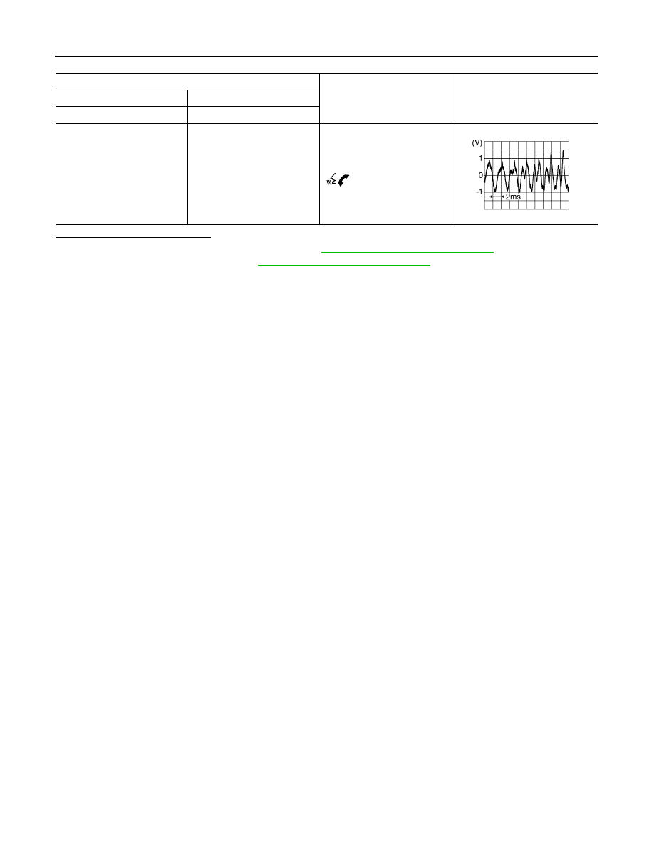
Audio unit connector M95
Condition
Reference value
(+)
(
−)
Terminal
Terminal
25
24
During voice guide output with
switch pressed.
SKIB3609E
AV
BLUETOOTH® CONTROL SIGNAL CIRCUIT
AV-191
< DTC/CIRCUIT DIAGNOSIS >
[DISPLAY AUDIO WITH BOSE]
C
D
E
F
G
H
I
J
K
L
M
B
A
O
P
BLUETOOTH® CONTROL SIGNAL CIRCUIT
Diagnosis Procedure
INFOID:0000000009758905
Regarding Wiring Diagram information, refer to
.
1.
CHECK CONTROL SIGNAL CIRCUIT CONTINUITY
1. Turn ignition switch OFF.
2. Disconnect Bluetooth
®
control unit connector M45.
3. Check continuity between Bluetooth
®
control unit connector M45 and ground.
Is the inspection result normal?
YES
>> Replace Bluetooth
®
control unit. Refer to
AV-217, "Removal and Installation"
NO
>> Repair or replace harness or connectors.
Bluetooth
®
control unit
Ground
Continuity
Connector
Terminals
M45
4
—
Yes
21
22
24
Нет комментариевНе стесняйтесь поделиться с нами вашим ценным мнением.
Текст