Nissan Sentra. Instruction — part 501
WHEEL ALIGNMENT
FSU-7
< PERIODIC MAINTENANCE >
C
D
F
G
H
I
J
K
L
M
A
B
FSU
N
O
P
WARNING:
• Always perform the following procedure on a flat surface.
• Make sure that no person is in front of vehicle before pushing it.
1. Bounce the front of vehicle up and down to stabilize the vehicle height (posture).
2. Push on the rear wheel to move the vehicle straight ahead about 5 m (16 ft).
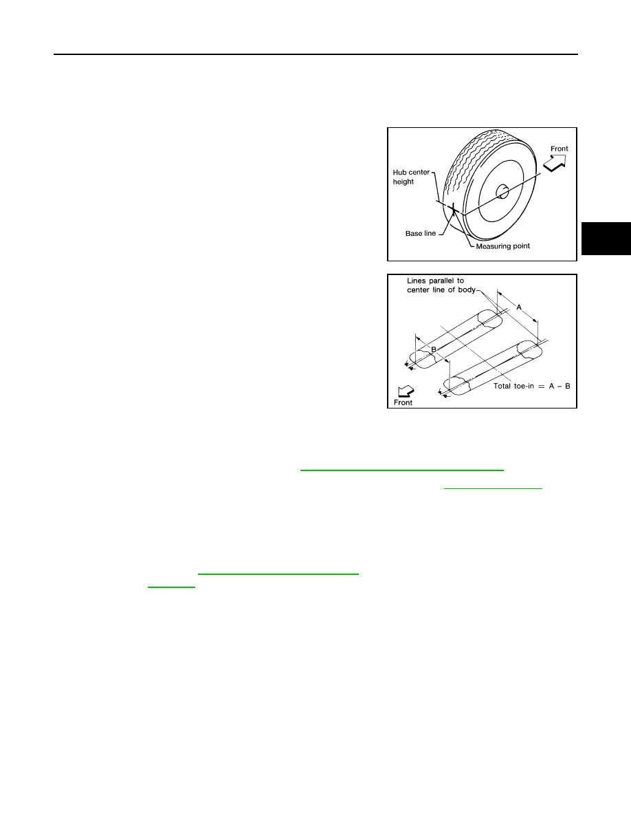
3. Put a mark on base line of the tread (rear side) of both tires at
the same height of hub center. These are measuring points.
4. Measure the distance (A) from the rear side.
5. Push on the rear wheel to move the vehicle slowly ahead and to
rotate the wheels 180 degrees (1/2 turn).
CAUTION:
If the wheels have rotated more than 180 degrees (1/2 turn),
try the above procedure again from the beginning. Do not
push vehicle backward.
6. Measure the distance (B) from the front side.
7. Use the formula below to calculate total toe-in.
• If the total toe-in is outside the specification, adjust the total toe-in. Refer to
.
Adjustment
INFOID:0000000009758752
TOTAL TOE-IN
Loosen the steering outer socket. Adjust the length using the steering inner socket.
CAUTION:
• Always evenly adjust both toe-in alternately and adjust the difference between the left and right to
the standard.
• Always hold the steering inner socket when tightening the steering outer socket.
AFA050
SFA234AC
Total toe-in
: A - B
Total toe-in specification
: Refer to
FSU-23, "Wheel Alignment (Unladen*1)"
.
Toe-in
: Refer to
FSU-8
< REMOVAL AND INSTALLATION >
FRONT COIL SPRING AND STRUT
REMOVAL AND INSTALLATION
FRONT COIL SPRING AND STRUT
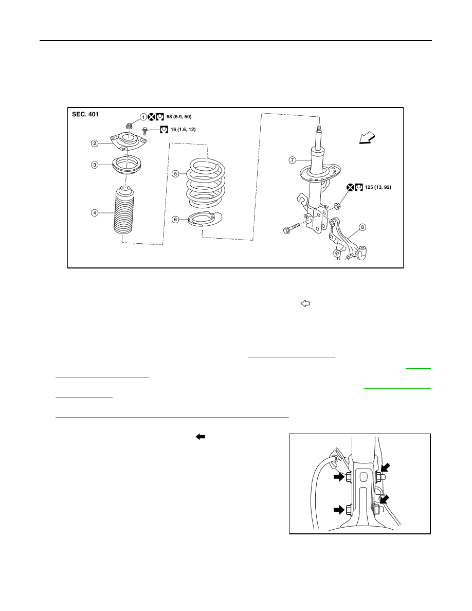
Exploded View
INFOID:0000000009758753
Removal and Installation
INFOID:0000000009758754
REMOVAL
1. Remove the wheel and tire using power tool. Refer to
.
2. Remove the lock plate from the front coil spring and strut and reposition the brake hose. Refer to
3. Disconnect the stabilizer connecting rod from the front coil spring and strut. Refer to
4. Remove the wheel sensor bolt. Position the wheel sensor and the wheel sensor harness aside. Refer to
BRC-106, "FRONT WHEEL SENSOR : Removal and Installation"
.
5. Use a jack to support the transverse link and the steering knuckle.
6. Remove the lower strut nuts and bolts (
).
1.
Piston rod lock nut
2.
Strut mount insulator
3.
Strut mount bearing
4.
Bound bumper
5.
Coil spring
6.
Lower rubber seat
7.
Strut
8.
Steering knuckle
Front
AWEIA0289ZZ
WEIA0179E
FRONT COIL SPRING AND STRUT
FSU-9
< REMOVAL AND INSTALLATION >
C
D
F
G
H
I
J
K
L
M
A
B
FSU
N
O
P
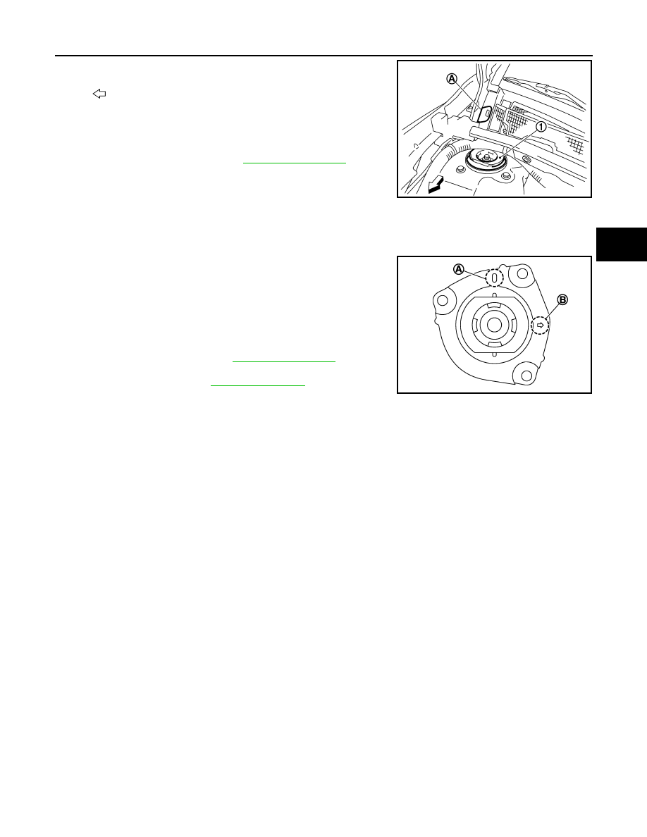
7. Remove the grommet (A) from the cowl top cover.
8. Access 1 upper strut bolt through the grommet hole.
9. Remove the upper strut bolts from the strut mount insulator (1).
10. Remove the front coil spring and strut.
11. Inspect the components. Refer to
INSTALLATION
Installation is in the reverse order of removal.
CAUTION:
Do not reuse piston rod lock nut or strut nuts.
• Install the front coil spring and strut with the identification mark (A)
of the strut mount insulator facing toward the front of the vehicle
and the arrow (B) facing the outboard side.
NOTE:
The identification mark "0" shows the (RH) strut mount insulator
and "1" shows the (LH).
• Perform the final tightening of the bolts and nuts under unladen
conditions with the tires on level ground.
• Complete the inspection. Refer to
• After replacing the strut, always follow the disposal procedure to
discard the old strut. Refer to
.
: Front
JSEIA0418ZZ
JPEIA0246ZZ
FSU-10
< REMOVAL AND INSTALLATION >
TRANSVERSE LINK
TRANSVERSE LINK
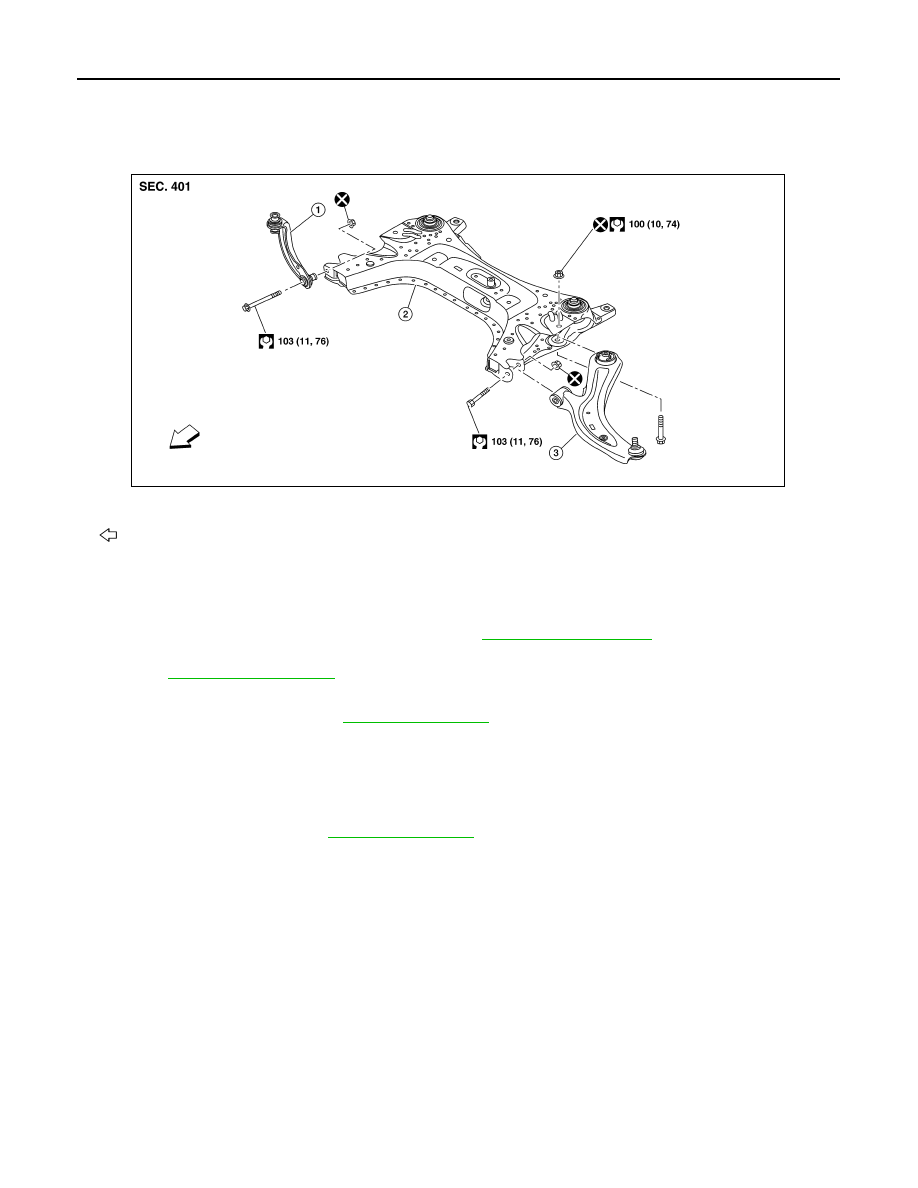
Exploded View
INFOID:0000000009758755
Removal and Installation
INFOID:0000000009758756
REMOVAL
1. Remove the wheel and tire using power tool. Refer to
.
2. Remove the nut and bolt from the lower ball joint. Disconnect the transverse link from steering knuckle.
.
3. Remove the nuts and bolts and disconnect the transverse link from the suspension member.
4. Inspect the components. Refer to
INSTALLATION
Installation is in the reverse order of removal.
CAUTION:
Do not reuse the transverse link nuts.
• Perform the final tightening of the nuts and bolts under unladen conditions with the tires on level ground.
• Complete the inspection. Refer to
Inspection
INFOID:0000000009758757
INSPECTION AFTER REMOVAL
Check the following items, and replace the parts if necessary.
Transverse Link
• Check the transverse link and bushing for deformation, cracks or damage.
• Check the ball joint boot for cracks or other damage, and also for grease leaks.
Swing Torque
1. Move the ball joint at least ten times by hand to check for smooth movement with no binding.
1.
Upper link
2.
Front suspension member
3.
Transverse link
Front
AWEIA0297ZZ
Нет комментариевНе стесняйтесь поделиться с нами вашим ценным мнением.
Текст